Advertisement
Quick Links
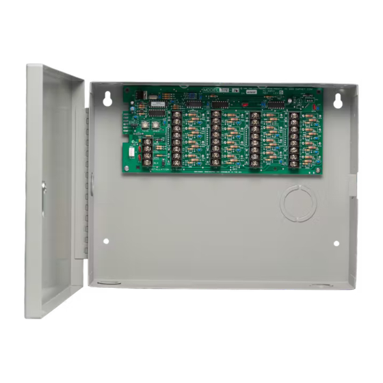
714-8/16 AND 715-8/16 ZONE
EXPANDERS
Installation Guide
Z5+
Z1+
1k
EOL
KYPD LX
Z5-
Z1-
TENS ONES
Z6+
Z2+
Z6-
Z2-
TXD
RED
Z7+
Z3+
Z7-
YEL
Z3-
Z8+
GRN
Z4+
Z8-
BLK
Z4-
Figure 1: 714-16 Zone Expander
DESCRIPTION
The 714-8 and 714-16 provide
an additional eight or sixteen
supervised zones for connecting
burglary and non-powered fire
alarm initiating devices to the panel.
The 715-8 and 715-16 provide an
additional eight or sixteen 12 VDC
ungrounded (Class B, Style A)
powered zones for connecting
two-wire smoke detectors.
The zone expanders provide
terminal strips, a jumper for LX-Bus
or Keypad Bus designation, and a
transmit data LED to indicate panel
communication.
All fire device installations
must be in accordance with the
manufacturer instructions, NFPA
standards, and Authority Having
Jurisdiction (AHJ) requirements.
Compatibility
•
XT30/XT50 Panels and
XR150/XR550 Panels
•
714-8: 1k-4.7k Ohm EOL (Lev E
and higher)
•
714-16: 1k Ohm EOL
•
715-8/715-16: 3.3k Ohm
What is Included?
•
One 714-8, 714-16, 715-8, or 715-16
Zone Expander
•
Eight or Sixteen 1K Ohm
Resistors (714-8/714-16) or 3.3K
Ohm Resistors (715-8/715-16)
•
One Model 340 or 350 Enclosure
with Lock and Key
1
Z9+
Z13+
Z9-
Z13-
Z10+
Z14+
Z10-
Z14-
Z11+
Z15+
Z11-
Z15-
Z12+
Z16+
Z12-
Z16-
2
3
PROGRAM THE PANEL
After completing each of the following steps, press CMD to
advance to the next option. Refer to the panel programming guide
as needed.
Reset the panel and enter 6653 (PROG) at a keypad.
1.
In ZONE INFORMATION, program the expansion zones as
2.
any of the panel's burglary or fire zone types. You can also
program zones as an Arming (AR) zone type when they are
being used with key switches.
3.
Press CMD until STOP displays. Press a top row select key or
area to save programming.
MOUNT THE ENCLOSURE
Mount the enclosure in a secure, dry place. It is not necessary
to remove the zone expander circuit board when installing the
enclosure.
The enclosure can be surface or flush mounted using the holes
provided. Each of the four sides have dual 1/2" and 3/4" conduit
knockouts for running wires out of the enclosure. For more
information, refer to Figure 2.
WIRE THE ZONE EXPANDER
The zone expanders provide a 3-pin header with jumper used to
select the connection type.
To connect the expander to the Keypad Bus, place the jumper
across the two leftmost pins. To connect the expander to the LX-
Bus, place the jumper across the two rightmost pins. For more
information, refer to Figure 2.
Connect to the LX-Bus
To wire the 714-8/714-16, join the red, yellow, green, and black
wires to a 4-wire harness and connect it to the LX-Bus.
To wire the 715-8/715-16, connect the red wire to panel Terminal 11
(Smoke power terminal). This allows Sensor Reset to drop power
to the module and devices connected to its zones. Join the yellow,
green, and black wires to a 4-wire harness and connect it to the
LX-Bus.
Advertisement

Related Manuals for DMP Electronics 714-8/16


Summary of Contents for DMP Electronics 714-8/16
- Page 1 714-8/16 AND 715-8/16 ZONE EXPANDERS Installation Guide PROGRAM THE PANEL After completing each of the following steps, press CMD to advance to the next option. Refer to the panel programming guide Z13+ KYPD LX Z13- as needed. TENS ONES Z10+...
- Page 2 Figure 2: Zone Expander Wiring SET THE ZONE EXPANDER ADDRESS 714-8/16 and 715-8/16 Point Zone Expanders use two rotary switches (TENS and ONES) to set the zone expander address. For keypad bus addresses, the ONES switch must be set to a starting address that communicates the status of the first four zones (Z1 through Z4) on the expansion module.
- Page 3 LED stops flashing and System Trouble appears in the keypad display. 714-8/16 AND 715-8/16 INSTALLATION GUIDE DIGITAL MONITORING PRODUCTS...
- Page 4 Zone Protection diagram in the XR150/XR550 Canadian Installation guide. Otherwise, 714/715 zones can only be used in low risk applications. ULC Residential Fire (XR150/XR550 Series Panels) Refer to the appropriate panel compliance listing guide for the complete list of UL approved smoke detectors. 714-8/16 AND 715-8/16 Accessories 340-G Panel Enclosure, gray...
Need help?
Do you have a question about the 714-8/16 and is the answer not in the manual?
Questions and answers