Table of Contents
Advertisement
Quick Links
Advertisement
Table of Contents

Related Manuals for Heraeus Biofuge Primo R


Summary of Contents for Heraeus Biofuge Primo R
- Page 1 Biofuge Instructions for use...
- Page 2 How to use this manual Use this manual to get acquainted with your centrifuge and its accessories. The manual helps you to avoid inappropriate handling. Overleaf you will find a graphic Make sure to keep it always close to the centrifuge. representation of the control panel with a survey of the most important A manual that is not kept handy cannot provide...
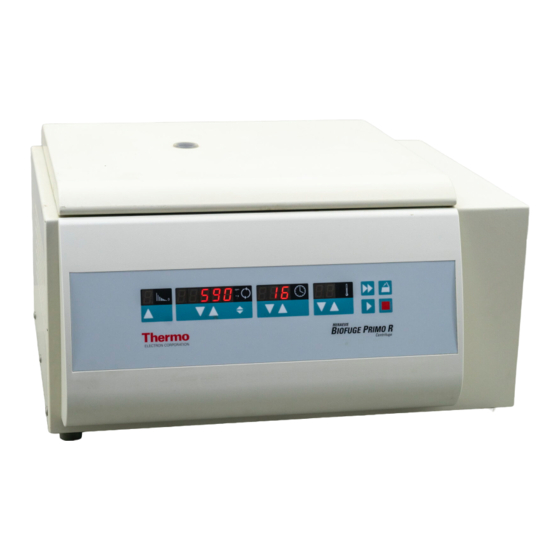
- Page 3 speed/RCF temperature quick run braking run time profiles open lid 5 0 0 0 9.59 stop start Biofuge "set" key "set" keys "set" keys rpm/RCF display switch back panel socket for mains cable mains switch...
- Page 4 Control panel of the Keys Biofuge primo R Start: normal start Stop: manual stop Open lid: open lid (possible only with the instrument Display switched on) Braking profiles Quick run: short-term operation of the centrifuge as Continuous display : braking profile last used, 1 - 9;...
-
Page 5: Table Of Contents
Conformity to current standards....... 5 Important application information for rotor Safety instructions in this manual ......5 7500 7599! ............24 The Biofuge primo R ........7 Aerosol-tight application .........25 Permissible rotor temperature......26 Safety systems............7 Lifetime of the rotor ..........26 Properties .............. - Page 6 Contents Selecting the run time..........34 Troubleshooting........45 Preselected run time........... 34 Emergency lid release ..........45 Continuous operation ......... 34 Problems you can handle yourself......47 Selecting the temperature ........35 In case you must call the Service ......54 Starting the centrifuge ..........36 Technical data............55 Unbalance detection..........
-
Page 7: For Your Safety
For your safety For your safety Proper use The centrifuge is designed to separate liquid- Heraeus centrifuges are manufactured according to suspended materials having different densities and current technical standards and regulations. Nonethe- particle size, respectively. The maximum sample den- less, centrifuges may pose dangers if sity is 1.2 g/cm... -
Page 8: Handling
For your safety • Do not centrifuge toxic or radioactive substances or • Never use the centrifuge if the paneling has been pathogenic microorganisms unless you have taken partially or totally removed. proper precautions. • Changes in mechanical or electrical components Such precautions can e.g. -
Page 9: Conformity To Current Standards
For your safety Conformity to current standards Safety instructions in this manual Heraeus centrifuges are manufactured and tested This symbol denotes potential hazards to according to the following standards and regulations: persons. This symbol denotes potential damage to the centrifuge or parts in its immediate sur- roundings. - Page 10 For your safety for your notes...
-
Page 11: The Biofuge Primo R
The Biofuge primo R The Biofuge primo R Safety systems The Biofuge primo R is equipped with a number of The figure below shows a general view of the Biofuge safety systems: primo R with open lid and the rotor put into place. -
Page 12: Properties
The Biofuge primo R Properties Items delivered The Biofuge primo R is a laboratory centrifuge for use Items delivered with the centrifuge comprise: with a variety of rotors and a large number of commer- − a special cap nut for fixing the rotor cially available centrifuge tubes. -
Page 13: Functions And Features
The Biofuge primo R Functions and features Part / function Description / feature design / housing galvanized sheet chassis with armored shell tank stainless steel drive induction drive without carbon brushes key and display board key and display elements covered by an easy-care protective foil... -
Page 14: The "Easycontrol" User Interface
The Biofuge primo R The "Easycontrol" user interface Function Feature lid opening automatic unlocking via "open lid" key ( (unlocking in case of power failure: see chapter "Troubleshooting") start start key ( stop stop key ( "quick run" mode pressing the "quick run“ key ( ) actuates maximum acceleration up to the maximum permissible speed;... - Page 15 The Biofuge primo R Function Feature diagnostic messages • alternating display "rotor"/maximum speed or RCF (acknowledgment by pressing the start key) • incorrectly closed lid: display "OPEN" • general instrument malfunction (error messages with ERROR codes, see "Troubleshooting"...
- Page 16 The Biofuge primo R for your notes...
-
Page 17: Rotor Program And Accessories
Rotor program and accessories Rotor program and accessories The Biofuge primo R is delivered without rotor! You may choose from among a large variety of rotors available as accessories. (see Rotor program, Table 1) In addition, there are sets of adapters and reduction sleeves for diverse commercially available vessels (see Adapters, Table 2). -
Page 18: Rotor Program
Rotor program and accessories Rotor program Table 1: Rotor program (1) Rotor designation fixed-angle rotor swinging bucket swinging bucket 6 x 50 ml Falcon rotor 4 x 100 rotor 12 x 1.5 / 2.0 order no. 7500 7590 7500 7591 7500 7592 buckets and caps see Table 2 maximum permissible load [ g ]... - Page 19 Rotor program and accessories Rotor program Table 1: Rotor program (2) Rotor designation microliter rotor microliter rotor 24 x drum rotor 24 x 2 ml aluminum 2 ml Polypropylene order no. 7500 7593 7500 7599 7500 7595 maximum permissible load [ g ] 24 x 4 24 x 4 8 x 80...
-
Page 20: Adapters
Rotor program and accessories Adapters Table 2: Adapters (1) Adapters for fixed-angle rotor max. vessel size number number color order no. 7500 7590 ∅ x length adapter rotor [ mm ] 1.5 ml microvessels 11 x 57 7600 2905 3.5 ml 11 x 100 7500 3091 6.5 ml... - Page 21 Rotor program and accessories Table 2: Adapters (2) Buckets and adapters for incl. max. number number color order no. swinging bucket rotor 7500 7591 rubber vessel size buffer ∅ x length adapter rotor [ mm ] Roundbucket 100 ml/50 ml conical 1807 44 x 100 –...
- Page 22 Rotor program and accessories Table 2: Adapters (3) Racks for number number color order no. drum rotor 7500 7595 adapter rotor 1.5 ml microvessels yellow 7600 1499 1.5 / 2 ml microvessels 7600 1244 1.5 / 2 ml microvessels (60°) white 7500 1498 0.3 ml microcapillary vessels...
-
Page 23: Before Use
Before use Before use Damage to the centrifuge by jolting Transport and installation during transport and sudden drop- ping! The centrifuge is delivered in an special box. Cut it open and remove the protective material. Transport the centrifuge only in the upright position using the special box provided with the instrument, When transporting the centrifuge, con-... -
Page 24: Positioning The Instrument
Drehzahl: siehe Rotor kin. Energie: 1NNN Nm Spannung: 220V~ Fabr.-Nr.: Frequenz: 50/60 Hz Bestell-Nr.: 7500NNNN Strom: Leistung: Biofuge primo R zulässige Dichte des Füllgutes:N,N kg/cm type plate with indication mains switch socket for of voltage and frequency power cord... -
Page 25: Operation
Operation Operation 0.00 Switching on the centrifuge Turn on the mains switch on the back of the instrument. Biofuge For a couple of seconds the following reading appears in the control panel: 8.8.8.8.8. 8.8.8. 8.8.8. Lid operation Opening the lid Press the "open lid"... -
Page 26: Inserting The Rotor
O-Ring on the motor shaft must be in perfect condition. 2. Turn the rotor so that the notch for engaging the The rotors approved for the Biofuge primo R are de- drive shaft points downward. tailed in the chapter "Rotor program and accessories". -
Page 27: Handling Of Rotors And Seals
Operation 5. If you have placed the rotor correctly, you can Handling of rotors and seals screw on the cap nut easily and secure it with the The swiveling pegs of the swinging bucket rotors and tubular socket wrench delivered with the instru- the corresponding notches of the buckets must be ment. -
Page 28: Important Application Information For Rotor 7500 7599
Operation Important application information for rotor Position the snap-on lid. 7500 7599! Press the rotor lid down onto the rotor until To attach the rotor, use the acorn nut with ball head! the snap-on catch engages onto the ball (Order no. 70056208) of the acorn nut. -
Page 29: Aerosol-Tight Application
Operation Aerosol-tight application Attention : Please check that your sample containers are suitable for the centrifugal application desired. only with screw-on top 75003326 and not with open container lids! (16060 x g ; temperature in uncooled devices approx. 10 K above room temperature) The following steps have to be carried out: Please observe the permissible filling volumes! •... -
Page 30: Permissible Rotor Temperature
Operation Permissible rotor temperature The rotor 7500 7599 may be used only within temperature range -4 °C to +40 °C. Pre-cooling in the freezer is not permitted. Lifetime of the rotor There are no restrictions to the service life of the high performance rotor 7500 3325 B. -
Page 31: Loading The Rotor
The smaller the unbalance of the centrifuge, the better The Biofuge primo R can reach high rotational speeds the separation since separated zones are no longer implying enormous centrifugal force. The rotors are perturbed by vibration. -
Page 32: Loading Instruction For Rotors 7590 And 7595
Operation Loading instruction for rotors 7590 and 7595 Loading for aerosol-tight operation You must always equip all sample For the centrifugation of hazardous locations with adapters or sample samples you must always respect the racks! highest permissible sample amounts. The rotor 7590 may only be used with the lid in place. - Page 33 Operation Rotor vessel type / maximum filling volume leakage test microliter rotor Reakt 1.5 ml Reakt 2.0 ml 1.0 ml 1.5 ml 24 x 1.5 ml #7593 8 ml microliter rotor Reakt 1.5 ml Reakt 2.0 ml 1.0 ml 1.5 ml 24 x 2.0 ml #7599 8 ml fixed-angle rotor...
-
Page 34: Checking For Aerosol Tightness
Operation (not the bores themselves) using a pipette or sy- Checking for aerosol tightness ringe. • Place the rotor lid on top and screw it on. Check the aerosol tightness of your ATTENTION: Make sure that there is no spilled rotor whenever appropriate. -
Page 35: Placing The Tubes In The Rotor
Operation Placing the tubes in the rotor The rotor must be loaded symmetrically. When loading Uneven loading can in the extreme the rotor only partially, you must ensure that opposite case lead to actuation of the unbal- bores always receive tubes of equal weight (when cen- ance detection. -
Page 36: Entering Parameters
The centrifuge can be set to a minimum of 300 and a Braking curves maximum of 15,000 min (depending on the rotor). The Biofuge primo R offers a total of 9 running profiles You can adjust the speed in steps of 10 min . Proceed for optimally centrifuging samples and gradients. -
Page 37: Entering The Rcf Value
Operation a number of seconds, then changes to permanent Concerning the RCF value display. The speed is now stored. The relative centrifugal force (RCF) is given in multi- 5. For faster operation, you may shift the flashing cur- ples of the earth gravity g. It is a dimensionless number sor in the speed/RCF and in the run time panels: that allows one to compare the efficiency of separation or sedimentation of diverse instruments, since it is... -
Page 38: Selecting The Run Time
Continuous operation point mode. To switch the Biofuge primo R to the continuous mode, 2. By briefly pressing the input key you can now raise you must press the key... -
Page 39: Selecting The Temperature
Operation Selecting the temperature 4. Release the key as soon as you have reached the desired value, and fine tune if necessary by repeat- You can preselect the temperature in the range of edly pressing the key. -9 °C to +40 °C. The temperature display flashes for a number of sec- (Please consult the standard diagram in the Appendix to obtain the attainable values.) -
Page 40: Starting The Centrifuge
Operation Starting the centrifuge Unbalance detection Once the rotor is properly placed, the mains switch is In case there is an unbalance in the rotor, this is indi- turned on and the lid is closed, you can start the centri- cated at a speed slightly exceeding approximately 300 fuge. -
Page 41: Stopping The Centrifuge
Operation Stopping the centrifuge Temperature regulation at rest Stopping with preset time The precise control becomes active once the rotor has been identified; the speed panel then displays "End". Normally the run time has been preselected, and all you have to do is wait until the centrifuge terminates If the rotor has not been identified (lid has been closed the run automatically at the end of the preset time. -
Page 42: Short-Time Centrifugation
Operation Short-time centrifugation Removing the rotor For short-term operation, the Biofuge primo R is To remove the rotor, you must follow the steps de- equipped with a "quick run" function. scribed for insertion in reverse order. Short-term centrifugation is started by pressing the "quick run"... -
Page 43: Maintenance And Care
Maintenance and care Maintenance and care Cleaning Pull mains plug before cleaning the Maintenance operations to be carried out instrument! by the customer The main care is to clean regularly (or as need arises) For the protection of persons, the environment and the the housing, the rotor chamber, the rotor and the ac- equipment you are obliged to clean the centrifuge regu- cessories. -
Page 44: Disinfection
Maintenance and care Disinfection Organic solvents decompose the lu- bricant of the motor bearing. The drive shaft may jam. Infectious material may enter the cen- trifuge if the vessel fractures or in the Liquids and especially organic sol- case of spillage. vents must not come into contact with Risk of infection if touched! the drive shaft and the ball bearing... - Page 45 Maintenance and care • To decontaminate the affected rotor chamber and • You may disinfect the rotor and the accessories as rotor, use only disinfectants approved by KENDRO. described in the following section. Be sure to follow These agents are to be used according to the In- the pertinent safety procedures for handling infec- structions for Use supplied with the respective disin- tious material.
-
Page 46: Disinfection With Eau De Javelle
Maintenance and care Disinfection with eau de Javelle For reasons of safety you may auto- These bleaching agents contain extremely aggressive clave the rotor 7500 7599 maximally 10 hypochlorite solutions and may in no case be used with times! aluminium rotors. To protect the rotor 75007599 as far The rotor must be cleaned and rinsed with distilled as possible you must take the following precautions: water before being autoclaved. -
Page 47: The Service Of Kendro
Maintenance and care The Service of KENDRO Warranty conditions Kendro Laboratory Products GmbH recommends an- The warranty period starts with the day of delivery. nual servicing of the centrifuge and the accessories by Within the warranty period the centrifuge is repaired or the authorized service or skilled personnel. - Page 48 Maintenance and care for your notes...
-
Page 49: Troubleshooting
Troubleshooting Troubleshooting Proceed as follows: 1. Make sure that the rotor stands still (consult window Emergency lid release in the lid). In case of a power failure you cannot open the lid nor- mally using the normal electrical lid unlocking mecha- Never brake the rotor using your hands nism. - Page 50 Troubleshooting 4. Finally, push the rip cord back into the instrument and close the opening with the plastic plug. Once the power is back, you can connect the instru- ment to the mains supply and turn it on.
-
Page 51: Problems You Can Handle Yourself
Troubleshooting Problems you can handle yourself If problems other than those described in the following tables arise, you must consult the authorized service. Error Behavior of the Possible causes and corrective measures centrifuge Displays The motor stops. Mains failure or not connected. remain dark The rotor stops without 1. - Page 52 Troubleshooting Error Possible causes and corrective measures Behavior of the centrifuge Lid cannot be Pressing the "open lid" Lid not correctly engaged or lid warped. opened. key has no effect. Check whether mains connection is OK and the instrument switched on (displays lit). Press lid down in the middle of the front section once, and actuate the "open lid"...
- Page 53 Troubleshooting Error Possible causes and corrective measures Behavior of the centrifuge Message "bAl" Rotor stops without Unbalance switch actuated. appears in braking. Open the instrument by pressing "open lid" key display. Check whether the rotor is properly loaded. Check whether a broken vessel or damage to the rotor was responsible for unbalance switch actuation.
- Page 54 Troubleshooting Error Possible causes and corrective measures Behavior of the centrifuge Message "Lid" Drive stops. Lid was opened manually during the run. appears in the Press the lid shut again. The instrument stops without braking. Rotor coasts to rest. display. If you want to continue the run, you must switch the instrument off and on again.
- Page 55 Troubleshooting Error Possible causes and corrective measures Behavior of the centrifuge E-04 Rotor stops without Temperature measurement impaired (probe breakage). braking to standstill. Switch the instrument off and on again. If the error persists, call our Instrument cannot be Service. operated.
- Page 56 Troubleshooting Error Possible causes and corrective measures Behavior of the centrifuge E-10 During self test after NV-RAM; error in program memory. switching on. Switch the instrument off and on again. If the problem persists, call Service. E-12 Rotor stops without Temperature measurement impaired.
- Page 57 Troubleshooting Error Possible causes and corrective measures Behavior of the centrifuge E-17 Lid does not open. Lid blocked or jammed. Press the front part of the lid centrally down once, and press the "open lid" key anew. Otherwise see "Emergency lid release" (page 45) E-19 During self test after Wrong NV-RAM or keyboard.
-
Page 58: In Case You Must Call The Service
Troubleshooting In case you must call the Service The last information displayed is the current cycle status. Should you need our Service, please tell us the order Cycle counter __235 no. and serial number of your instrument. You find the pertinent information at the back of the instrument near The values given are only examples! the socket for the mains plug. -
Page 59: Technical Data
Technical data Technical data Function/parameter Value environmental conditions indoor use max. elevation 2000 m above sea level max. relative humidity 80 % up to 31 °C; linearly decreasing down to 50 % relative humidity at 40 °C. permissible temperature of the environment +2 °C to +40 °C run time 1 min - 9 h 59 min, hold = permanent operation... -
Page 60: Electrical Connections/Fuses
Technical data Function/parameter Value compliance with standards Manufactured and checked in accordance with EN 61 010-1, EN 61 010-2-020, EN 50 081-1, EN 50 082-1. Electrical connections/fuses Order no. Voltage Frequency Nominal Power Fuse protection Fuse protec- current consumption of instrument tion of build- 7500 5440 230 V... -
Page 61: Appendix
Appendix Appendix Braking and acceleration curves Acceleration curves 4000 3000 2000 1000 Braking curves time [s]... - Page 62 Appendix 4000 3000 2000 1000 time [s]...
-
Page 63: Speed / Rcf Diagrams
Appendix Speed / RCF diagrams 75007590 fixed-angle rotor 6 x 50 ml (Falcon) RCF (r = 12,4 cm) 100000 RCF (r = 6,0 cm) 10000 1000 = 8500 min RCF (r ) = 10015 1000 10000 100000 speed [min... - Page 64 Appendix 75007591 swinging bucket rotor 4 x 50 ml (Falcon) / 4 x 100 ml 10000 RCF (r = 14,5 cm) RCF (r = 5,0 cm) 1000 = 4000 min RCF (r ) = 2584 1000 10000 speed [min...
- Page 65 Appendix 75007592 swinging bucket rotor 12 x 1,5 / 2,0 ml 100000 RCF (r = 8,7 cm) RCF (r = 4,7 cm) 10000 1000 = 13000 min RCF (r ) = 16438 1000 10000 100000 speed [min...
- Page 66 Appendix 75007593 fixed-angle rotor 24 x 1.5 / 2 ml 100000 RCF (r = 8,7 cm) RCF (r = 5,9 cm) 10000 1000 = 17000 min RCF (r ) = 28106 1000 10000 100000 speed [min...
- Page 67 Appendix 75007599 microliter rotor 24 x 1.5 / 2 ml 100000 RCF (r = 8,5 cm) RCF (r = 5,9 cm) 10000 1000 = 13000 min RCF (r ) = 16058 1000 10000 100000 speed [min...
- Page 68 Appendix 75007595 drum rotor 80 x 2 ml 100000 RCF (r = 8,7 cm) RCF (r = 3,8 cm) 10000 1000 = 13000 min RCF (r ) = 16436 1000 10000 100000 speed [min...
-
Page 69: Standard Values For Minimum Sample Temperature65
Appendix Standard values for minimum sample temperature Rotor #7590/6x Falcon 50ml Rotor #7593/24x2ml Alu (relativ e to room temperature 23°C) (relativ e to room temperature 23°C) 9000 11000 13000 15000 6000 6500 7000 7500 8000 8500 speed (min-1) speed (min-1) Rotor #7595/Trommel Rotor #7599/24x2ml PP (relativ e to room temperature 23°C) - Page 70 Appendix Standard values for minimum sample temperature...
-
Page 71: Autoclaving Protocol For Rotor 7500 7599
Appendix Autoclaving protocol for rotor 7500 7599 Date Remark Operator Signature... - Page 72 Appendix for your notes...
-
Page 73: Index
Index Index approved rotors 22 autoclaving 42 autoclaving cycle permissible maximum 42 autoclaving protocol acceleration curves 57 rotor 7500 7594 67 acceleration profiles 8, 10 acceleration time 14, 15 accessories 13 cap nut 8 tubular socket wrench 8 adapters bleaching agents fixed-angle rotor 16 for disinfection 42 microliter rotor 16... - Page 74 Index during run 36 racks 18 cleaning 39 closing the lid 21 conditions of warranty 43 continuous operation 34 control panel Easycontrol readings 8 user interface 8 corrosive substances Easycontrol user interface 10 protective vessels for 4 EC Guidelines 5 cursor electrical connections 56 shifting 33...
- Page 75 Index E-25 53 for disinfection 42 Message "rotor" 49 OPEN with lid closed 49 error messages 11 icons for denoting dangers and potential damage 5 indoor use 19 features 9 infectious material filling precautions in case of tube breakage 40 centrifuge tubes 27 inserting the rotor 22 fixed-angle rotor 14...
- Page 76 Index lid unlocking mechanism maximum permissible speed 36 manual 45 maximum sample density 3 lifetime microliter rotor 15 plastic tubes 27 min. temperature 14, 15 loading minimum distance for aerosol-tight operation 28 from wall 19 maximum 27 minimum sample temperature rotors 7590 and 7595 28 standard values 65, 66 location 19...
- Page 77 Index parameters radius 14, 15 radius of centrifugation entry for calculation of RCF value 33 partial loading of rotor 31 maximum 36 pathogenic microorganisms RCF / speed diagrams 59 protection against 4 RCF display 32 permissible speed 27 and rotor identification 33 plastic tubes RCF selection 10 limited lifetime 27...
- Page 78 Index rotor program 14 service contracts rotor temperature Kendro 43 permissible 26 setting rotors run time 34 approved 22 temperature 35 run profile 8 settings run time change during run 36 range 34 short-time operation 38 setting 34 socket wrench 8 run time display sodium fluorescein during run 36...
- Page 79 Index with continuous operation 37 protection against 4 with preset time 37 transport 19 substructure 19 precautions for 19 swinging bucket rotor 14 tube adapters 17 breakage with infectious material 40 buckets 17 tubes swinging bucket rotors for centrifugation 8 lubrication 23 switching from RCF to speed display and vice versa 32...
- Page 80 Kendro Laboratory Products GmbH Telefax: In the interest of continuous product development, we reserve the right to make Postbox 15 63 (+49) 61 81/ 3 57 49, Sales changes without express notice. D-63405 Hanau / Germany (+49) 55 22/ 31 62 76, Service Telephone: Telephone: 20056884...
Need help?
Do you have a question about the Biofuge Primo R and is the answer not in the manual?
Questions and answers