
Related Manuals for NASA Marine CLIPPER SPEED AND DISTANCE LOG


Summary of Contents for NASA Marine CLIPPER SPEED AND DISTANCE LOG
- Page 1 CLIPPER SPEED 23.5 KNOTS SPEED ILLUM TRIP TOTAL CLIPPER SPEED DISTANCE...
-
Page 3: Table Of Contents
INTRODUCTION INSTALLING THE DISPLAY INSTALLING THE PADDLE WHEEL GETTING STARTED CHANGING THE OPERATING MODE BACKLIGHT SETTING DISPLAYING SPEED DISPLAYING TRIP DISTANCE RESETTING THE TRIP DISTANCE TO ZERO DISPLAYING THE TRIP DISTANCE CHANGING THE UNITS OPERATING CONFIGURATION SWITCHING BETWEEN NAUTICAL AND STATUTE MILES DISPLAYING AVERAGE READINGS CHANGING THE CALIBRATION CALIBRATION EXAMPLE... -
Page 4: Introduction
INTRODUCTION The Clipper Speed and distance log is supplied complete with display unit, paddle wheel assembly, skin fitting and blanking cap. It is intended for operation from 12V ship’s supply, although, because of its low power consumption, it can be run from an external dry battery. -
Page 5: Installing The Paddle Wheel
Unscrew and remove the two wing nuts from the rear of the instrument and remove the stainless steel clamping bracket. Fit the “O” ring seal into the groove in the panel mounting face of the instrument. Ensure that it is correctly lying in its groove before fitting the instrument to the panel, which provides the watertight seal for the display. - Page 6 With the vessel out of water, drill a hole of 42mm diameter through the hull to take the paddle housing and use conventional methods for sealing. It is advisable to avoid the use of mastic materials - use a form of proprietary silicon sealant. Housing 20mm MINIMUM...
-
Page 7: Getting Started
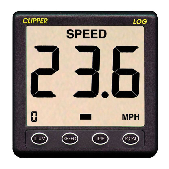
GETTING STARTED When the Clipper Distance & Log is first turned on, it automatically performs a number of self-test processes, and after a brief delay switches on the backlight illumination at the factory pre-set level. It then displays the speed in the previously selected mode of knots or MPH (as shown on Figure 3). -
Page 8: Backlight Setting
BACKLIGHT SETTING To set the display back light press the ILLUM key. Pressing ILLUM whilst `L` is shown on the display will gradually decrease the illumination. Pressing ILLUM whilst `H` is shown will gradually increase the illumination. A brief press of ILLUM will roster between ‘L’ and ‘H’. SPEED KNOTS ILLUM... -
Page 9: Displaying Speed
DISPLAYING SPEED SPEED KNOTS ILLUM SPEED TRIP TOTAL Figure 5- Speed Display If it is desired to display speed, press the button marked SPEED. The display changes to that shown on Figure 5, and the present speed is displayed. The acceleration bars below the middle digit (See Figures 4 and 5) show whether the speed is reducing (left arrow lit), the same (central bar lit), or is increasing (right arrow lit). -
Page 10: Resetting The Trip Distance To Zero
be when nautical miles is selected. Whenever the trip distance exceeds 99.9, the number to the right of the decimal is still stored in the unit, but the display changes to show whole miles, and the decimal point is removed. 48.6 N.MILES TRIP... -
Page 11: Displaying The Trip Distance
to the original trip reading. If the finger is left on the TRIP button after zero is displayed, F (for Finished) is shown to remind you that the trip distance clear is cleared. Normal operation of the trip reading is resumed when the finger is lifted. Note that any fractional distance in the trip distance when it is cleared is stored for adding to the total when new trip distances are measured. -
Page 12: Changing The Units Operating Configuration
If the total distance logged is greater then 9999, the display rolls over to 0 again. Whenever the total distance is less than 1000, none of the thousands digits are displayed. CHANGING THE UNIT`S OPERATIONAL CONFIGURATION Configuration describes the settings held permanently in the unit to affect how it operates. -
Page 13: Switching Between Nautical And Statute Miles
SWITCHING BETWEEN NAUTICAL AND STATUTE MILES The distance setting can be switched between statute miles and nautical miles (and back again as often as needed) for both trip and total distances. Press the SPEED button to switch between the two modes. -
Page 14: Changing The Calibration
ILLUM ILLUM SPEED TRIP TOTAL SPEED TRIP TOTAL Figure 9 -Switching between Fast and Averaged speed display modes CHANGING THE CALIBRATION The calibration factor determines the number of revolutions of the paddle wheel required to represents 0.1 miles or nautical miles. The calibration of the unit is set up in the factory and the value is stored in the unit’s memory. -
Page 15: Calibration Example
Any changes are automatically applied to both speed and distance measurements, and are always permanently stored in the unit even when it is switched off. If the factory-fresh unit (with a pre-set calibration factor of 100) is found to under-read by, for example, 6% the calibration factor must be increased by 6% to 106 to corect the under reading, The calibration factor is increased by pressing the TOTAL button, and decreased by pressing the SPEED button. -
Page 16: Returning To Normal Operating Mode
Get into configuration mode, and press TRIP . Suppose the calibration factor is already set to the factory preset value of 100. To reduce it by 5, press the SPEED Button 5 times to reduce the unit`s calibration factor to 95 (which is 5 less than the original calibration factor of 100). - Page 17 NMEA OUTPUT The Clipper Log has an NMEA output version 0183 sending sentences $VWVHW and $VWVLW. The blue lead is the NMEA output positive. CLIPPER LOG REPEATER Connect the Clipper Log Repeater as follows: Red wire to positive (+12V) Silver/Black wire to negative Blue wire to Blue wire on Clipper Log master unit (NMEA) The log repeater repeats all information from the Clipper log master unit.
- Page 20 Prior to unpacking this instrument read and fully understand the installation instructions. Only proceed with the installation if you are competent to do so. Nasa Marine Ltd. will not accept any responsibility for injury or damage caused by, during or as a result of the installation of this product.
Need help?
Do you have a question about the CLIPPER SPEED AND DISTANCE LOG and is the answer not in the manual?
Questions and answers