
Related Manuals for Home Decorators Collection Bentley II 129828


Summary of Contents for Home Decorators Collection Bentley II 129828
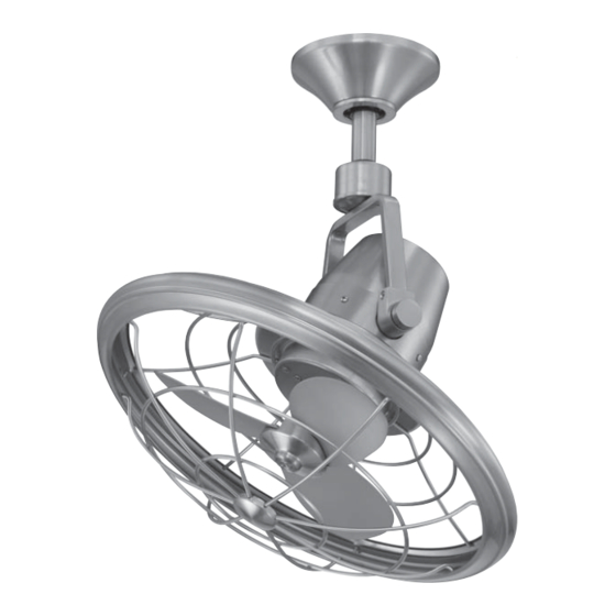
- Page 1 129 828 Model: AL14-BN 120 V~ 60 Hz 44 W Read and follow all the instructions before using this product. Bentley II Ceiling Fan Owner’s Manual Bentley II Ventilador de Techo de 45.7 Manual del Propietario...
- Page 2 To ensure your combinations of wood and brass personal safety and to maximize finishes, solid designer colors, and the performance of your fan, our unique glass and crystal please read this manual designs. thoroughly. Bentley II by Home Decorators Collection...
- Page 3 VENTILADOR DE TECHO/CEILING FAN Marca/Brand: Home Decorators Collection Modelo/Model: 129828 120 V~ 60 Hz 44 W Consumo de energía por unidad de tiempo en operación (Energy Consumption): 48,145 Wh Importador/Importer: SERVICIOS HOME DEPOT, S. DE R.L. DE C.V. Ricardo Margain 605, Santa Engracia, San Pedro Garza García, Nuevo León, C.P.
-
Page 4: Table Of Contents
18” Bentley II Thank you for purchasing our ceiling fan. This product has been manufactured with the highest standards of safety and quality. Ceiling Fan by HDC Date Purchased Store Purchased Table of Contents 129 828 Model No. Safety Rules ....1 Serial No. -
Page 5: Safety Rules
Safety Rules - Read and Save These Instructions To reduce the risk of electric shock, insure electricity has been turned off After making electrical connections, spliced conductors should be turned at the circuit breaker or fuse box before beginning. upward and pushed carefully up into outlet box. The wires should be spread apart with the grounded conductor and the equipment-grounding All wiring must be in accordance with the National Electrical Code conductor on one side of the outlet box and ungrounded conductor on the... -
Page 6: Unpacking Your Fan
Unpacking Your Fan Unpack your fan and check the contents. You should have the following items: Canopy assembly Receiver+6 wire nuts Electrical Hardware (3 Plastic Wire Nuts) Transmitter+holder+2 mounting screws Ball/downrod assembly 9 Volt battery Coupling cover Allen wrench Fan motor assembly WARNING DO NOT INSTALL OR USE FAN IF ANY PART IS DAMAGED OR MISSING. -
Page 7: Installing Your Fan
Installing Your Fan Tools Required Figures 1~2 are examples of different ways to mount the outlet box. Phillips screwdriver, straight slot screwdriver, step ladder and wire cutters. Outlet Box Figure 3 To hang your fan where there is an existing fixture Mounting Options but no ceiling joist, you may need an installation Outlet Box... - Page 8 WARNING Hanging the Fan Align the holes at the bottom of the downrod with the holes in the coupling on top of the THE FAN MOTOR ASSEMBLY IS SHIPPED WITH A STOPPER TO PREVENT MOVEMENT DURING REMEMBER to turn off the power. Follow the motor housing (Figure 5).
- Page 9 Installing Fan to WARNING UL Listed Outlet Box THE TAB IN THE RING MUST REST IN THE the Electrical Box GROOVE OF THE HANGER BALL AS FIGURE 7. FAILURE TO PROPERLY SEAT THE TAB IN THE GROOVE COULD CAUSE DAMAGE TO WIRING. WARNING 120V Wires...
- Page 10 Making the Electrical from the receiver. Secure the wire connections with the plastic wire connecting nuts provided. Connections Frequency Switch (Figure 11) Receiver to house supply wires electrical connections: Connect the black (hot) WARNING wire from the ceiling to the black wire marked TO AVOID POSSIBLE ELECTRICAL SHOCK, BE "AC in L"...
- Page 11 Finishing the Fan WARNING SUPPLY CIRCUIT MAKE SURE THE TAB ON THE HANGING Installation BRACKET PROPERLY SITS IN THE GROOVE IN THE HANGER BALL BEFORE ATTACH- Ground ING THE CANOPY TO THE BRACKET BY Tuck connections neatly into ceiling outlet TURNING THE HOUSING UNTIL IT DROPS Conductor BLACK...
- Page 12 Disassembling Your Fan This fan is pre-assembled the rear guard, blade and front guard in factory before shipping for your easy installation, checking all screws are tighten and securely in place, following the below procedures if you are intended to disassemble the fan for cleaning: (Fig.
-
Page 13: Operating Your Fan
Operating Your Fan Restore power to ceiling fan and test for proper operation. Install 9V battery (included). to prevent damage to transmitter, remove the battery if not used for long periods. (Fig. 14) WARNING: May explode or leak if recharged, disposed of in fire or dissected. -
Page 14: Care Of Your Fan
Care of Your Fan Troubleshooting PROBLEM SOLUTION Here are some suggestions to help you maintain your fan. Because of the fan’s natural movement, some Fan will not start Check main and branch circuit fuses or breakers. connections may become loose. Check the all Check line wire connections to the fan. -
Page 15: Specifications
Specifications FAN SIZE SPEED VOLTS AMPS WATTS N.W. G.W. C.F. 0.24 12.62 20.84 6.26 kgs 8.5 kgs 0.28 18.28 1097 29.02 18” MED. 4.9’ (13.77 lbs) (18.70 lbs) 0.36 41.83 1611 41.29 HIGH These are approximate measures. They do not include Amps and Wattage used by the light kit. Importer: SERVICIOS HOME DEPOT, S.
Need help?
Do you have a question about the Bentley II 129828 and is the answer not in the manual?
Questions and answers