Table of Contents
Advertisement
Advertisement
Table of Contents

Summary of Contents for ASTRO D2-15
- Page 3 SAFETY PRECAUTIONS SAFETY PRECAUTIONS GENERAL CONSIDERATIONS SERVICING EQUIPMENT 1. Read and follow these instructions. Failure to do 1. Only trained personnel are to operate and service this could result in severe personal injury or death. equipment. 2. Additional safety instructions and/or symbols are 2.
-
Page 4: Table Of Contents
TABLE OF CONTENTS Chapter 1 Safety Precautions Chapter - Page # Chapter 2 Description & Speci cations Description ............................2 - 1 Features ..............................2 - 1 Speci cations ............................2 - 2 Motor Speed, Adhesive Pressure, and Flow Rate ..............2 - 2 Dimensions ............................ - Page 5 Chapter 5 Preventive Maintenance Maintenance ............................5 - 1 Preventive Maintenance ........................5 - 1 Chapter 6 Troubleshooting General Troubleshooting ........................6 - 1 Tank does not heat ..........................6 - 1 Zone Over-temperature ........................6 - 1 Applicator and Hose Heat Slowly ....................6 - 1 Motor does not turn ...........................
- Page 6 Chapter 8 Component Illustration and Bill of Materials Recommended Spare Parts ......................8 - 1 Tank Components ..........................8 - 2 Bushing and Assembly Shaft ......................8 - 3 Motor Group & Mounting Hardware .................... 8 - 4 Pump/Motor Assemblies ........................8 - 6 Pump Group ............................
- Page 7 (HAR) standard and rated for 70 °C (158 °F). A HAR approved Type B plug and strain relief for power cord are required to meet standard IEC 309. Power conducting wires must be nominal 5.3 mm (10 AWG) maximum and nominal 2.1 mm (14 AWG) minimum. ©Astro Packaging Rev D D2-15 Manual-19600-10-D215...
- Page 8 Disconnect electrical power at external source. Failure to do so can cause electrical shock. WARNING: High Pressure. System contents under pressure. Can cause serious injury and burns or equipment and property damage. Relieve pressure before servicing. ©Astro Packaging Rev D D2-15 Manual-19600-10-D215...
- Page 9 Alarm Actual Temp Source Power Valve Group Manual Task Input Output The manufacturer reserves the right to make design changes for product improvement. This manual may not re ect all details of these improvements. ©Astro Packaging Rev D D2-15 Manual-19600-10-D215...
- Page 10 (HAR) standard and rated for 70 °C (158 °F). A HAR approved Type B plug and strain relief for power cord are required to meet standard IEC 309. Power conducting wires must be nominal 5.3 mm (10 AWG) maximum and nominal 2.1 mm (14 AWG) minimum. ©Astro Packaging Rev D D2-15 Manual-19600-10-D215...
- Page 11 Disconnect electrical power at external source. Failure to do so can cause electrical shock. WARNING: High Pressure. System contents under pressure. Can cause serious injury and burns or equipment and property damage. Relieve pressure before servicing. ©Astro Packaging Rev D D2-15 Manual-19600-10-D215...
- Page 12 Alarm Actual Temp Source Power Valve Group Manual Task Input Output The manufacturer reserves the right to make design changes for product improvement. This manual may not re ect all details of these improvements. ©Astro Packaging Rev D D2-15 Manual-19600-10-D215...
-
Page 13: Description
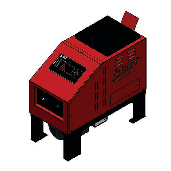
The D215 Hot Melt Unit is a light-duty to medium-duty machine used for melting and pumping a variety of materials. The melt unit consists of a heated melt tank and a motor-driven, positive displacement V4 series gear pump. The melt unit is compatible with a variety of Astro Packaging pattern generators and head drivers. -
Page 14: Speci Cations
(110 lb./hr @ 250 psi) *These gures are based on standard, packaging grade hot melt materials at 1 PaS (1,000 cps). These gures vary with adhesive and tank temperature. Consult your Astro Packaging representative for non-standard material requirements. ©Astro Packaging Rev D... -
Page 15: Dimensions
Dimensions ©Astro Packaging Rev D D2-15 Manual-19600-10-D215... -
Page 16: Installation
Hoses are normally installed on an automatic melt unit at the factory with no user installation required. If they are not installed, see Hose Replacement. Refer to the enclosed Heated Supply Hoses product manual (Astro Packaging P/N 19600-24) for complete installation and service information. - Page 17 Power conducting wires must be rated for intended current and 75° C (167° F). 120 VAC L1/N 240 VAC L1, L2 Single-phase service Single-phase service Operation DANGER: Disconnect power before opening front panel. Hazardous voltage can shock, burn, or cause death. ©Astro Packaging Rev D D2-15 Manual-19600-10-D215...
-
Page 18: Start-Up
Start-Up 1. Become familiar with the temperature controller information in the D2-15 manual. 2. Install the melt unit. 3. Fill the tank with hot melt material to 38 mm (1.5 in.) from the top. 4. Turn the unit on, and allow for 30 minutes of warm-up time. - Page 19 • To decrease the pressure, turn counterclockwise. • To achieve the minimum pressure and the lowest ow rate, turn the knob fully counterclockwise. Gradually turn the knob clockwise until the desired pressure and ow rate are achieved. ©Astro Packaging Rev D D2-15 Manual-19600-10-D215...
-
Page 20: Storage & Disposal Of The Application System
Storage and Disposal of the D2-15 Application System Temporary Storage of the Unit 1. Flush the adhesive application system with ushing uid (PN RB-5), following the instructions detailed in Chapter 6 of this manual. 2. Clean or replace both the output lter and the tank, following instructions detailed in Chapter 6. -
Page 21: Programming Temperature Set-Points
Hose 1 Gun 1 Hose 2 Press and release the Menu button until the desired Menu Gun 2 is displayed. To increase or decrease values press Up or Down arrows To exit press Program ©Astro Packaging Rev D D2-15 Manual-19600-10-D215... -
Page 22: Set Offset Temperature
Menu is displayed. Standby Tank Hose1 Gun 1 Hose2 Gun 2 Over temp Tank Hose1 Gun 1 Hose2 Gun 2 To increase or decrease values press the Up or Down arrows To exit press Program ©Astro Packaging Rev D D2-15 Manual-19600-10-D215... -
Page 23: Set Automatic Wakeup
Program, Menu (4X), Enter Year Month Date Hours Press and release the Menu button until the desired Minutes Menu is displayed. To increase or decrease values press the Up or Down arrows To exit press Program ©Astro Packaging Rev D D2-15 Manual-19600-10-D215... -
Page 24: Save And Register Setting
Press and release the Menu button until the K1 and the date it was revised (20-MAR-2010). desired Menu is displayed. To exit press Program This menu is for viewing only, it can’t be altered. ©Astro Packaging Rev D D2-15 Manual-19600-10-D215... -
Page 25: Performance Various Maintenance Tasks
Menu is displayed. System Calibration 240 Ohms System Calibration Frequency 60 Hz System Calibration Voltage xxx.x V Test LED Lamps (LED Test, Run Now) Standby/Ready Tank Hose 1 Gun 1 Hose 2 Gun 2 ©Astro Packaging Rev D D2-15 Manual-19600-10-D215... - Page 26 Program, Menu (7X), Enter Current Level xxx % Change Level 1.9-100% Press and release the Menu button until the desired Menu is displayed. To increase or decrease values press Up or Down arrows To exit press Program ©Astro Packaging Rev D D2-15 Manual-19600-10-D215...
-
Page 27: Performance Various System Tasks
Automatic On/Off, 7 day clock timer On/Off Security Lock Level Off – 1 – 2 – 3 (see next sheet) Level 3 is recommended To change values press the Up or Down arrows To exit press Program ©Astro Packaging Rev D D2-15 Manual-19600-10-D215... -
Page 28: Security Lock Level
Not visible Automatic Wakeup Unlock Unlock Unlock Not visible Set Clock Calendar Unlock Unlock Unlock Not visible Save and Register Settings Not visible Display/Set Audit Variables Performance Various System Tasks Unlock Unlock Unlock Unlock ©Astro Packaging Rev D D2-15 Manual-19600-10-D215... - Page 29 Gun 2 Set Offset Temperatures Motor Cut OffTank Hose 1 Gun 1 Hose 2 Gun 2 StandbyTank Hose 1 Gun 1 Hose 2 Gun 2 Over temperatureTank Hose 1 Gun 1 Hose 2 Gun 2 ©Astro Packaging Rev D D2-15 Manual-19600-10-D215...
- Page 30 Power Set Mode 7 is recommended Disable hose and gun 1 Disable hose and gun 2 Trigger Safety Enable ON for handguns Automatic On/Off, 7 Day clock Timer Security Lock Level 1 is recommended ©Astro Packaging Rev D D2-15 Manual-19600-10-D215 4-10...
- Page 31 ©Astro Packaging Rev D D2-15 Manual-19600-10-D215 4-11...
-
Page 32: Chapter 5 Preventive Maintenance
Purge tank and hose(s). Inspect hose(s). Verify hose(s) properly supported. Minimum bend radius is 20.32 cm (8 in.) when hot. Check temperatures. Adjust temperatures according to Temperature Controller manual. Clear applicator nozzles. Inspect/Replace Pump Filter ©Astro Packaging Rev D D2-15 Manual-19600-10-D215... -
Page 33: Chapter 6 Troubleshooting
The temperature controller shuts off power to all zones if one zone reaches 20° over set- point. Applicator and hose heat slowly, 1. Adjust the hose and applicator settings. Inadequate low voltage. heat levels can affect performance. ©Astro Packaging Rev D D2-15 Manual-19600-10-D215... -
Page 34: Motor Does Not Turn
Refer to Ch. 3 for start-up cautions. 6. Increase the hose temperature by 4-10°C (25-50°F). If there is no change, consult Astro Packaging regarding the application. Contact Astro Packaging Technical Services department for assistance at (800) 642-7876 ©Astro Packaging Rev D D2-15 Manual-19600-10-D215... -
Page 35: Chapter 7 Repair & Replacement
4. Disconnect the hose electrical connector [4]. 5. Remove the screws from the hose-mounting block [5]. 6. Loosen the hose JIC tting [1], and remove the hose from the tting [2] on the ow control block [3]. ©Astro Packaging Rev D D2-15 Manual-19600-10-D215... - Page 36 4. Attach the hose electrical connector [4] 5. Tuck the hose electrical connector [4] under the melt unit. 6. Position and support the hose before using. 7. After heating the hose, tighten the JIC swivel tting [1]. ©Astro Packaging Rev D D2-15 Manual-19600-10-D215...
-
Page 37: Tank Heater Replacement
See the electrical schematic included with the melt unit. 7. Reinstall the housing. NOTE: The tank heater connections at the power board are J6 and J7, and are fused by F1 and F2. ©Astro Packaging Rev D D2-15 Manual-19600-10-D215... -
Page 38: Tank Rtd Sensor Replacement
5. Coat the RTD sensor lightly with heat sink compound. 6. Slide the new RTD sensor [2] into its bore. 7. Route the RTD lead wires in their original locations, as noted in Step 4. 8. Reinstall the housing. ©Astro Packaging Rev D D2-15 Manual-19600-10-D215... -
Page 39: Tank Over-Temperature Thermostat Replacement
7. Position the thermostat in the appropriate location on the tank base, and attach it using the original mounting screws. 8. Reconnect the over-temperature thermostat wire connectors, and reinstall the housing. NOTE: The over-temperature thermostat plugs into the power board at J8. ©Astro Packaging Rev D D2-15 Manual-19600-10-D215... -
Page 40: Motor Replacement
12. Test the motor for correct rotation. While looking down on the motor, the motor shaft should turn counterclockwise. The cooling fan may spin in the opposing direction, so it is important to judge the correct rotation by the motor shaft. ©Astro Packaging Rev D D2-15 Manual-19600-10-D215... -
Page 41: Pump Filter Installation & Replacement
8. Insert the new lter [4] into the ow control block [5]. 9. Inspect the o-ring [3], and replace it if it is damaged. 10. Install the tting [2], o-ring [3] and cap [1] securely into the ow control block [5] ©Astro Packaging Rev D D2-15 Manual-19600-10-D215... -
Page 42: V4 Pump & Flow Control Block Replacement
14. Adjust the adhesive pressure by turning the ow control knob [1]. Refer to Section 4.2 Adjustments. 15. Test the melt unit, adjust the pressure and check for leaks. 16. Return the melt unit to service. ©Astro Packaging Rev D D2-15 Manual-19600-10-D215... -
Page 43: V4 Pump Block Assembly Replacement
[3]. Reinstall the hoses and pressure gauge. Warm up the melt unit. When the unit is hot, re-tighten the screws mounted through the pump block [3]. Return the melt unit to service. ©Astro Packaging Rev D D2-15 Manual-19600-10-D215... -
Page 44: Chapter 8 Component Illustration And Bill Of Materials
Fuse, 8 amp, 5 X 20mm 12014-5 Fuse, 5 amp, 5 X 20mm 939683 Fuse, 6.5 amp, 5 X 20mm 10760-50 Pump lter D200109 Assembly, Tank RTD, 100 ohm D200111 Assembly, Over-temp Thermostat, 475° ©Astro Packaging Rev D D2-15 Manual-19600-10-D215... -
Page 45: Tank Components
Kit, Tank Heater, 120 V, 750 W D212600 Kit, Tank Heater, 240 V, 750 W D212600-2 Tank Seal 70020 Tank Lid Assembly 79283-15 D2-15 Tank Assembly 70827-60 D2-15 Melt Grid 70827-1 Knob 14517-99 Lid, Outer Black 70586-462 Lid, Inner, Gold Zinc 70586-463 ©Astro Packaging Rev D... - Page 46 Bushing Assembly 70827-71 Gear Grip w/ keyway 18425-9/16 Gear Grip Sleeve 18425-9C Retainer 70601 Shaft Seal 10483 Socket Head Cap Screw, 1/4-20 X 1.75 in. 14431-GDO * To replace shaft only, order items 2,7,8. ©Astro Packaging Rev D D2-15 Manual-19600-10-D215...
-
Page 47: Motor Group & Mounting Hardware
Bolt, Hex, 3/8-16 X 1.5 in., 86 rpm motor 14433-KAN Lock Washer, .25 in. ID 14451-GA Flat Washer, 1/2 in. 14456-GA Nut 1/4-20 14441-GA Screw, Hex, 1/4-20 X 1 in. 14433-GAK Capacitor, 86 rpm motor (not shown) 18416-10 ©Astro Packaging Rev D D2-15 Manual-19600-10-D215... - Page 48 ©Astro Packaging Rev D D2-15 Manual-19600-10-D215...
-
Page 49: Pump/Motor Assemblies
Pump/Motor Assemblies Item Description Part Number V4-675 Pump, with 86 rpm motor, 120 VAC, 50/60 Hz 79357-99 V4-675 Pump, with 86 rpm motor, 240 VAC, 50/60 Hz 79357-100 ©Astro Packaging Rev D D2-15 Manual-19600-10-D215... - Page 50 ***This page is intentionally left blank*** ©Astro Packaging Rev D D2-15 Manual-19600-10-D215...
-
Page 51: Pump Group
10493-145 O-ring, Viton, 0.614 in. ID X 0.070 in. W 10417 O-ring, Te on, 0.614 in. ID X 0.070 in. W 10493-024 Pump Filter, 50 Mesh 10760-50 * Parts included in V4-675 Pump Kit ©Astro Packaging Rev D D2-15 Manual-19600-10-D215... - Page 52 ©Astro Packaging Rev D D2-15 Manual-19600-10-D215...
-
Page 53: Flow Control Group
90° Fitting, No. 6 JIC, Straight Thread, Long 11447-01 Filter, 50 Mesh, Standard 10760-50 10505-08 O-ring, Hi-Temp. , No. 8 Fitting, Filter Retainer/Purge Valve 74456 11421-6B Cap, No. 6 JIC, Long Plastic Knob 14517-13 ©Astro Packaging Rev D D2-15 Manual-19600-10-D215 8-10... - Page 54 ©Astro Packaging Rev D D2-15 Manual-19600-10-D215 8-11...
- Page 55 TC500 Control Board D250014 Main Circuit Breaker 120 V D212015 Main Circuit Breaker 240 V 12010-5 12055 B-25 Pump Circuit Breaker 120 V Pump Circuit Breaker 240 V 12055A-15 Lamp Amber (power and pump) 12030-10 ©Astro Packaging Rev D D2-15 Manual-19600-10-D215 8-12...
-
Page 56: Tc500 Fuses
Part Number TC500 Power board D250015 F1, F2 Tank Heater, Power board fuse, 8 amp 12014-8B Motor, Power Board Fuse 5 amp 12014-5B F4, F5 Hose/gun heater, Power Board Fuse, 6.3 Amp 939683 ©Astro Packaging Rev D D2-15 Manual-19600-10-D215 8-13... - Page 57 TC500 Connections Item Connection Descriptions Control Ribbon Cable J3, J4 24 vdc Solenoid(s) Power Supply Tank Heater #2 Tank Heater #1 Tank Over-temp Motor/Circuit Breaker trip signal Hose/Head #2 Hose/Head #1 ©Astro Packaging Rev D D2-15 Manual-19600-10-D215 8-14...
- Page 58 **** This page is intentionally left blank. **** ©Astro Packaging Rev D D2-15 Manual-19600-10-D215 8-15...
-
Page 59: Exterior Panel And Controls
Item No. Part No. Description Qty. 70586-467 Chassis, Base 70586-465 Electrical Panel 70586-471 Housing 70586-472 Front Door 70586-466 Power & Pump Panel Lid with Hinge 70586-468 Inner Lid 70586-4681 70586-473 Access Cover Plate ©Astro Packaging Rev D D2-15 Manual-19600-10-D215 8-16... - Page 60 Component Illustration: Exterior Panel and Controls Parts List ©Astro Packaging Rev D D2-15 Manual-19600-10-D215 8-17...
- Page 61 **** This page is intentionally left blank. **** ©Astro Packaging Rev D D2-15 Manual-19600-10-D215 8-18...
- Page 62 38 °C (100 °F) 45-48 77-89 66 °C (150 °F) 156-157 239-281 93 °C (200 °F) 172-201 285-335 121 °C (250 °F) 149 °C (300 °F) 177 °C (350 °F) 204 °C (400 °F) ©Astro Packaging Rev D D2-15 Manual-19600-10-D215...
- Page 63 Handgun Hoses, RTD Sensor, L4 Hose Handgun Hoses, RTD Sensor, L4 Hose Handgun Hoses, RTD Sensor, L4 Hose 21261 (115 VAC) 127-140 86-96 75-79 53-58 49-52 39-41 37-39 21263 (230 VAC) 510-563 347-384 298-314 212-235 199-209 153-169 149-157 ©Astro Packaging Rev D D2-15 Manual-19600-10-D215...
- Page 64 Motor Wiring ©Astro Packaging Rev D D2-15 Manual-19600-10-D215...
- Page 65 Wiring Diagram 120V ©Astro Packaging Rev D D2-15 Manual-19600-10-D215...
- Page 66 Wiring Diagram 240V ©Astro Packaging Rev D D2-15 Manual-19600-10-D215...
- Page 67 *** This page is intentionally left blank.*** ©Astro Packaging Rev D D2-15 Manual-19600-10-D215...
- Page 68 C. Astro Packaging is not responsible for repair or replacement of any product that has been subject to abuse, misuse, alteration, accident, or negligent use, nor for repairs made by an unauthorized person or with parts other than those provided by Astro Packaging.
- Page 69 Date Received ________________ Start-Up Date ______________ Invoice No. _____________ Product Model/Description________________________________ Serial No. ______________ Product Part Number _____________________________________Order No. ______________ Date Received ________________ Start-Up Date ______________ Invoice No. _____________ Astro Packaging 3845 E. Miraloma, Unit A, Anaheim, CA. 92806 (714) 572-1094 (800) 642-7876 toll free (714) 572-1943 fax...
Need help?
Do you have a question about the D2-15 and is the answer not in the manual?
Questions and answers