Advertisement
Quick Links
Advertisement

Related Manuals for Dancover GH152100

Summary of Contents for Dancover GH152100
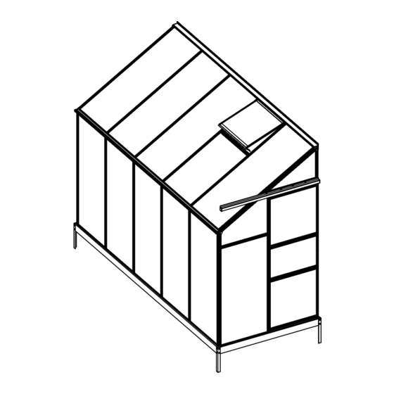
- Page 1 Manual Greenhouse Lean-to 1,27x3,04x2,12m 29-11-2019...
- Page 2 Assembly Instructions PRODUCT SIZE(LxWxH):304X127X212CM PLEASE READ CAREFULLY BEFORE ASSEMBLY...
- Page 3 CONTENTS...
- Page 4 Safety Warning & Advice KEEP WORKING AREA CLEAN AND DRY A cluttered, damp or wet working area may cause injuries. PREPARE A FLAT AND LEVEL BASE Make sure your greenhouse is located on a flat and level surface. DO NOT INSTALL THE GREENHOUSE ON A WINDY DAY OR IN AN AREA SUBJECT TO HIGH WINDS Although this greenhouse is designed to withstand greater wind loads than many other greenhouses, do not install it in on a windy day or in an area which is subject to high winds.
- Page 5 PART Base Assembly M6X10 M4.2X16 16*S01 4*S01 Fixing the greenhouse to the base is recommended. It is best to do this at the end, after the greenhouse has been fully assembled.
- Page 6 Use a powered screwdriver to fix the self-tapping screws (Z01) through the cills (L08A, L10 and L13) and base plinth (A1 and B1). The screws should be evenly spaced to ensure a neat appearance. The recommended spacing of the screws is 238mm. You can mark the painted surfaces with a pencil. L08A L08A L08A...
- Page 7 PART PART PART L01A L01B L01C L03B L04A J01R PART L05B L02A J01L L02B J02R L02C J02L L02D L03B PART 35+2 M6X10 35+2 L01A L01B M4X10 L08A L01D M4X10 L03B 103+5 M4.2X16 L04B L12A L05A PART PART PART PC/Glass...
- Page 8 PART Vent Assembly M4.2X16 M4X10 2*S02 Slide 2 bolts (S02) into the bolt channel (L21) and fix the handle (W06) in the middle 4*Z01...
- Page 9 PART Door Assembly M4.2X16 16*Z01...
- Page 10 PART NO QTY L01A L01C L04A M4.2X16 L01C L04A L01A 1. Lay out the glazing bars (L01A,L01C, and L04A) and the cill (L10). Ensure that the cill upstand is on the inside and that L01A&L01C is the correct way round. 2.
- Page 11 PART NO QTY L05B M4.2X16 M6X10 M6X10 L05B L05B L04A L01A 1. Fix 1 x L05B to L01A and L04A with the self-tapping screws (Z01) using a powered screwdriver. Ensure that L05B is fixed at a right angle (90 degrees) to the glazing bars (L01A and L04A).
- Page 12 PART NO QTY L03B M6X10 M6X10 Slide the lower glazing panels (Y2) into position. Slide 2 bolts (S01) into the inside L03B bolt channel and fix L03B to L05B. L03B L03B 2*S01 L03B L05B Slide the higher glazing panels (Y1 and Y13) into position.
- Page 13 PART NO QTY L01B M4.2X16 L01B Front Wall L01A Fix L01B to L01A,L01C and L04A using the W01 and W05 angled plates fixed with self-tapping screws (Z01) using a powered screwdriver. The inside of the glazing bars feature guide lines which indicate Be careful to ensure that the screws are in the correct position (see detail drawings below).
- Page 14 PART NO QTY L01A L01D L04B M4.2X16 L04B L01D L01A 1. Lay out the glazing bars (L01A, L01D, L04B) and the cill (L13). Ensure that the cill upstand is on the inside and that L01A&L01D is the correct way round. 2.
- Page 15 PART NO QTY L05A M4.2X16 L05A L05A L04B L01A L01D L01D 1. Fix the horizontal brace (L05A) to the glazing bars (L01A, L01D and L04B) with the self-tapping screws (Z01) using a powered screwdriver. Ensure that L05A is fixed at a right angle (90 degrees) to the glazing bars.
- Page 16 PART NO QTY L03B M6X10 L03B L03B M6X10 L03B 2*S01 L03B L05A 1. Slide 2 bolts (S01) into the inside each L03B bolt channel and fix L03B to L05A. 2. Slide the higher glazing panels (Y8) into position. L03B 3. Slide 2 bolts (S01) into the inside L03B bolt channel and fix L03B to L01D and L04B.
- Page 17 PART NO QTY L01B Rear Wall M4.2X16 1. Slide the higher glazing panels (Y1, Y13) into position. 1. Fix L01B to L01A, L01D and L04B using the W01 & W05 angled plates fixed with self-tapping screws (Z01) using a powered screwdriver. The inside of the glazing bars feature guide lines which indicate the correct screw positions (see detail drawings below).
- Page 18 PART NO QTY L08A BACK M6X10 M6X10 L01D L01A L01C&D FRONG L01A L08A 3*S01 3*S01 L01C L08A Slide 3 bolts (S01) into each L01A,L01C and L01D bolt channel and fix L08A (2 bolts to be used later). L01A L01A L01B Screw L08A Position...
- Page 19 PART NO QTY L02A M4.2X16 L02A L02A L02A L02A Fix the glazing bars (L02A) to the cills (L08A) and the eaves (L07) with the self-tapping screws (Z01) using a powered screwdriver. The inside of the glazing bars feature guide lines which indicate the correct screw positions (see detail drawings below).
- Page 20 PART NO QTY L12A M4.2X16 M6X10 L01A L12A L01A Fix 1 x L12A to the glazing bars at a height of 615mm. Bolt L12A to L01A using the extra S01 bolt placed in the bolt channel earlier. Fix the L12A to L02A with the self-tapping screws (Z01) using a powered screwdriver.
- Page 21 PART NO QTY M6X10 L02B L02C M4.2X16 L01B Bolt the ridge (L06) to 2 * L01B, L01C & L01D using the extra S01 bolts placed in the bolt channels earlier. Please note, if extra bolts were not placed in the bolt channel earlier L01B must be unbolted at one end and moved enough to squeeze the bolts in.
- Page 22 Slide the roof vents into position along the ridge (L06). The top of the roof vent locates in a groove in the ridge (L06). Please note that the glazing bars obstruct the passage of the roof vents, which must be in position before the last of the glazing bars are fixed.
- Page 23 PART NO QTY L02D M4.2X16 L02D After the roof vents are in position, fix the last of the glazing bars (L02D) to the eaves (L07) and the ridge (L06) with the self-tapping screws (Z01) using a powered screwdriver.The inside of the glazing bars feature guide lines which indicate the correct screw positions (see detail drawings below).
- Page 24 PART NO QTY L03B M6X10 M6X10 L03B 1. Slide 4 bolts (S01) into the bolt channel on the inside of L03B horizontal framing. 2. Use 2 of the bolts (S01) to bolt L03B horizontal framing to the glazing bars. 3. Use the other 2 bolts (S01) to bolt the window pins (W08) to L03B. L02C L02D 4*S01...
- Page 25 PART NO QTY L12A L01B M4.2X16 M6X10 L12A 1. Make a pencil mark on the end roof glazing bars (L01B) at a height of 755mm from the bottom. 2. Bolt 1 x L12A at each end to 2 x L01B using the L01B extra S01 bolts placed in the bolt channels earlier.
- Page 26 PART NO QTY Panel Assembly The gutter (L09) locates in a groove in the eaves (L07). If required use a mallet.
- Page 27 PART NO QTY M6X10 1. Bolt the door support rail (L14) to the horizontal framing (L11) using 3 extra S01 bolts placed in the bolt channels earlier. Please note, if extra bolts were not placed in the bolt channel earlier L01A must be unbolted at one end and moved enough to squeeze the bolts in.
- Page 28 PART NO QTY M4.2X16 L01B 1. Adjust the door until it moves smoothly 2. Fix L14 to the end roof glazing bar (L01B) with the self-tapping screws (Z01) using a powered screwdriver. The inside of the glazing bars feature guide lines which indicate the correct screw positions (see detail drawings below).
- Page 29 PART NO QTY J01R J01L J02R J02L M4.2X16 Fix the cover caps (J01R/L, J02R/L and J03) carefully with the self-tapping screws (Z01). Be careful to ensure that the screws are driven in straight and in the correct position (see detail drawings below). Screw position J01L J01R...
- Page 30 Contact information Head office: Dancover A/S For more information Nordre Strandvej 119 G please visit: 3150 Hellebæk www.dancovershop.com Denmark National contact Denmark: 70 26 76 20 Spain: 911 436 828 denmark@dancover.com espana@dancover.com UK: 020 8099 7570 Italy: 02 479 21 198 uk@dancover.com...
Need help?
Do you have a question about the GH152100 and is the answer not in the manual?
Questions and answers