Table of Contents
Advertisement
Quick Links
Advertisement
Table of Contents

Related Manuals for Amazone Centaur 4001-2 Series


Summary of Contents for Amazone Centaur 4001-2 Series
- Page 1 Operating Manual Centaur 4001-2 5001-2 Super Special Mulch cultivator Please read and follow this operating manual before MG3012 putting the machine into BAG 0070.1 12.08 operation. Printed in Germany Keep it in a safe place for future use.
- Page 2 Reading the instruction Manual and following it should seem to be inconvenient and superfluous as it is not enough to hear from others and to realize that a machine is good, to buy it and to believe that now everything should work by itself. The person in question would not only harm himself but also make the mistake of blaming the machine for possible failures instead of himself.
- Page 3 D-49202 Hasbergen Phone: +49 5405 501-290 Fax: +49 5405 501-106 E-mail: et@amazone.de Online spare parts catalogue: www.amazone.de When ordering spare parts, always specify the (ten-digit) machine identification number. Formalities of the operating manual Document number: MG3012 Compilation date: 12.08 ...
- Page 4 Send us your suggestions by fax. AMAZONEN-WERKE H. DREYER GmbH & Co. KG Postfach 51 D-49202 Hasbergen Phone: +49 5405 501-0 Fax: +49 5405 501-234 E-mail: amazone@amazone.de Centaur BAG 0070.1 12.08...
-
Page 5: Table Of Contents
Table of Contents User information ..................8 Purpose of the document......................8 Locations in the operating manual ...................8 Diagrams used .........................8 General safety instructions.................9 Obligations and liability ......................9 Representation of safety symbols..................11 Organisational measures .......................12 Safety and protection equipment ...................12 Informal safety measures.......................12 User training...........................13 Safety measures in normal operation ..................14 Dangers from residual energy....................14... - Page 6 Table of Contents Dual-circuit service brake system..................43 5.3.1 Coupling the brake and supply lines ..................44 5.3.2 Uncoupling the brake and supply lines ................. 45 Hydraulic service brake system..................... 46 5.4.1 Coupling the hydraulic service brake system................ 46 5.4.2 Uncoupling the hydraulic operating brake system ..............
- Page 7 Table of Contents 11.5 Scraper...........................87 11.6 Changing the coulter (workshop work) ..................88 11.6.1 Changing the Vario-Clip coulter (workshop work) ..............88 11.7 Replacing discs (workshop work) ..................89 11.8 Replacing the levellers ......................89 11.9 Axle and brake ........................90 11.9.1 Draining the air reservoir......................91 11.9.2 Cleaning line filters.........................91 11.9.3...
-
Page 8: User Information
User information User information The "User information" section supplies information on using the operating manual. Purpose of the document This operating manual Describes the operation and maintenance of the machine. Provides important information on safe and efficient handling of the machine. -
Page 9: General Safety Instructions
General safety instructions General safety instructions This section contains important information on safe operation of the machine. Obligations and liability Comply with the instructions in the operating manual Knowledge of the basic safety information and safety regulations is a basic requirement for safe handling and fault-free machine operation. Obligations of the operator The operator is obliged only to let those people work with/on the machine who... - Page 10 General safety instructions Risks in handling the machine The machine has been constructed to the state-of-the art and the recognised rules of safety. However, there may be risks and restrictions which occur when operating the machine For the health and safety of the user or third persons, ...
-
Page 11: Representation Of Safety Symbols
General safety instructions Representation of safety symbols Safety instructions are indicated by the triangular safety symbol and the highlighted signal word. The signal word (DANGER, WARNING, CAUTION) describes the gravity of the risk and has the following significance: DANGER Indicates an immediate high risk, which will result in death or serious physical injury (loss of body parts or long term damage) if not avoided. -
Page 12: Organisational Measures
General safety instructions Organisational measures The operator must provide the necessary personal protective equipment, such as: Protective glasses Protective shoes Protective suit Skin protection, etc. The operation manual Must always be kept at the place at which the machine is operated. -
Page 13: User Training
General safety instructions User training Only those people who have been trained and instructed may work with/on the machine. The operator must clearly specify the responsibilities of the people charged with operation, maintenance and repair work. People being trained may only work with/on the machine under the supervision of an experienced person. -
Page 14: Safety Measures In Normal Operation
General safety instructions Safety measures in normal operation Only operate the machine if all the safety and protection equipment is fully functional. Check the machine at least once a day for visible damage and check the function of the safety and protection equipment. Dangers from residual energy Note that there may be residual mechanical, hydraulic, pneumatic and electrical/electronic energy at the machine. -
Page 15: Spare And Wear Parts And Aids
Immediately replace any machine parts which are not in a perfect state. Use only genuine AMAZONE spare and wear parts or parts approved by AMAZONEN-WERKE to ensure that the operating permit retains its validity in accordance with national and international regulations. -
Page 16: Warning Pictograms And Other Signs On The Machine
General safety instructions 2.13 Warning pictograms and other signs on the machine 2.13.1 Positioning of warning pictograms and other labels The following diagrams show the arrangement of the warning pictograms on the machine. Fig. 1 Fig. 2 Centaur BAG 0070.1 12.08... - Page 17 General safety instructions Always keep all the warning pictograms of the machine clean and in a legible state. Replace illegible warning pictograms. You can obtain the warning pictograms from your dealer using the order number (e.g. MD 075). Warning pictograms - structure Warning pictograms indicate dangers on the machine and warn against residual dangers.
- Page 18 General safety instructions Order number and explanation Warning pictograms MD 078 Risk of crushing of fingers/hand by accessible, moving parts of the machine! This danger can cause extremely serious injuries resulting in the loss of limbs. Never reach into the danger area when the tractor engine is running with the PTO shaft or hydraulic/electrical system connected.
- Page 19 General safety instructions MD 095 Read and understand the operating manual safety information before starting up the machine! MD 096 Risk of hydraulic fluid escaping under pressure from leaking hydraulic lines! This can inflict serious injuries with potentially fatal consequences if hydraulic fluid escaping at high pressure passes through the skin and into the body.
- Page 20 General safety instructions MD 114 This pictogram indicates a lubrication point MD 115 The maximum operating pressure of the hydraulic system is 200 bar. MD 132 The required tyre pressure is 1.8 bar. MD 136 The required tyre pressure is 4.3 bar. MD 145 The CE mark on the machine indicates compliance with the stipulations of the valid EU...
-
Page 21: Dangers Of Not Observing Safety Instructions
General safety instructions MD 174 Danger resulting from the unintentional movement of the machine! Causes serious injuries anywhere on the body or death. Secure the machine against unintentional movement before uncoupling the machine from the tractor. For this, use the parking brake and/or the wheel chock(s). -
Page 22: Safety Information For Users
General safety instructions 2.16 Safety information for users WARNING Risk of being crushed, cut, caught, drawn in or struck due to insufficient traffic and operational safety! Before starting up the machine and the tractor, always check their traffic and operational safety. 2.16.1 General safety and accident prevention information ... - Page 23 General safety instructions When coupling and uncoupling machines, move the support equipment (if available) to the appropriate position (stability). When actuating the support equipment, there is a danger of injury from contusion and cutting points! Be particularly careful when coupling the machine to the tractor or uncoupling it from the tractor! There are contusion and cutting points in the area of the coupling point between the tractor and the machine.
- Page 24 General safety instructions Machine transportation When using public highways, national road traffic regulations must be observed. Before moving off, check: the correct connection of the supply lines the lighting system for damage, function and cleanliness the brake and hydraulic system for visible damage ...
-
Page 25: Hydraulic System
Replace the hydraulic hose line if it is damaged or worn. Only use original AMAZONE hydraulic hose lines. The hydraulic hose lines should not be used for longer than six years, including any storage time of maximum two years. Even... -
Page 26: Electrical System
General safety instructions 2.16.3 Electrical system When working on the electrical system, always disconnect the battery (negative terminal). Only use the prescribed fuses. If fuses are used with too high a rating, the electrical system will be destroyed – danger of fire. ... -
Page 27: Brake System
General safety instructions 2.16.5 Brake system Only specialist workshops or recognised brake services may carry out adjustment and repair work on the brake system. Have the brake system checked regularly. If there are any functional faults in the brake system, stop the tractor immediately. -
Page 28: Tyres
Spare parts must meet at least the specified technical requirements of AMAZONEN-WERKE! This is ensured through the use of original AMAZONE spare parts. Centaur BAG 0070.1 12.08... -
Page 29: Loading And Unloading
Loading and unloading Loading and unloading Loading and unloading with a tractor WARNING There is a risk of an accident when the tractor is unsuitable and the machine brake system is not connected to the tractor or is filled. Correctly couple the machine to the tractor, before loading the machine onto a transport vehicle or unloading it from a transport vehicle. - Page 30 Loading and unloading Loading using a lifting crane WARNING Risk of crushing due to accidental falling of a machine attached to a load carrier during loading and unloading! Only attach your lifting gear to/at the designated points. Never remain in or enter the area below a raised, unsecured load.
-
Page 31: Product Description
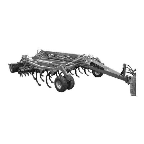
Product description Product description This section: Provides a comprehensive overview of the machine structure. Provides the names of the individual modules and controls. Read this section when actually at the machine. This helps you to understand the machine better. The Centaur mulch cultivator comes with foldable frame in the following variants: ... - Page 32 Product description Fig. 7 (1) Running gear and roller wheels (4) Depth adjustment of outer roller wheels (2) Strippers (5) Chassis hydraulic cylinder (3) Central roller wheel hydraulic cylinder (6) Hydraulic cylinder for folding extension arm Centaur BAG 0070.1 12.08...
-
Page 33: Safety And Protection Equipment
Product description Safety and protection equipment Stop tap to prevent accidental lowering of the tines during maintenance work (Fig. 8/3), yellow hose mark. Stop tap in position A – shutoff position Stop tap in position B – default position ... -
Page 34: Supply Lines Between The Tractor And The Machine
Product description Supply lines between the tractor and the machine Supply hoses in parking position: Hydraulic hose lines Electric cable for lighting Connection to hydraulic brake Pneumatic brake system Brake line with coupling head (yellow) ... -
Page 35: Transportation Equipment
Product description Transportation equipment Fig. 11: Rear lighting (1) Rear lights; brake lights; turn indicators (2) Warning signs (square) (3) Red reflectors (triangular) (4) Red reflectors (round) (5) Licence plate holder 2 x 3 reflectors, yellow (not pictured) (at side, max. 3m apart) Fig. -
Page 36: Intended Use
Compliance with all the instructions in this operating manual. Execution of inspection and maintenance work. Exclusive use of original AMAZONE spare parts. Other uses to those specified above are forbidden and shall be considered as improper. For any damage resulting from improper use: ... -
Page 37: Rating Plate And Ce Marking
Product description The following danger areas exist: Between the tractor and machine, especially when coupling and uncoupling. Near moving parts. When the machine is in motion. Within the pivot range of the machine wing. Underneath raised, unsecured machines or parts of machines. ... -
Page 38: Technical Data
Product description Technical Data Centaur 4001-2 5001-2 Super Special Super Special Working width [mm] 4,000 4,000 5,000 5,000 Transport width [mm] 3,000 3,000 3,000 3,000 Number of tine rows (offset) Number of tines Number of rows of discs/spring tines Number of discs/spring tines Disc diameter [mm] Track width... -
Page 39: Necessary Tractor Equipment
Product description 4.10 Necessary tractor equipment For the machine to be operated as intended, the tractor must fulfil the following requirements: Tractor engine power 4001-2 Special from 110 kW 4001-2 Super from 147 kW 5001-2 Special from 147 kW 5001-2 Super from 185 kW Electrical system ... -
Page 40: Structure And Function
Structure and function Structure and function The following section provides information on the machine structure and the functions of the individual components. Functionality The Centaur is suitable for the following tasks: Ploughing grassland without preparatory work Tilling ground for mulch sowing ... -
Page 41: Hydraulic System Connections
Structure and function Hydraulic system connections WARNING Danger of infection from escaping hydraulic fluid at high pressure! When coupling and uncoupling the hydraulic hose lines, ensure that the hydraulic system is depressurised on both the machine and tractor sides. If you are injured by hydraulic fluid, contact a doctor immediately. All the hydraulic hose lines possess the following coloured markings to allow assignment of the appropriate hydraulic function to the pressure line of a tractor control unit. -
Page 42: Coupling The Hydraulic Hose Lines
Structure and function 5.2.1 Coupling the hydraulic hose lines WARNING Risk of being crushed, cut, caught, drawn in or struck due to faulty hydraulic functions when the hydraulic hose lines are connected incorrectly! When coupling the hydraulic hose lines, observe the coloured markings on the hydraulic plugs. -
Page 43: Dual-Circuit Service Brake System
Structure and function Dual-circuit service brake system The machine does not have a parking brake. Always secure the machine with the wheel chocks before you uncouple the machine from the tractor. The machine is equipped with a dual-circuit pneumatic braking system with hydraulically actuated braking cylinder for the brake shoes in the brake drums. -
Page 44: Coupling The Brake And Supply Lines
Structure and function Fig. 17/... (1) Brake cylinder (2) Equalising tank for brake fluid Fig. 17 5.3.1 Coupling the brake and supply lines WARNING Risk of contusions, cuts, dragging, catching or knocks from incorrectly functioning brake system. When coupling the brake and supply line, ensure that: ... -
Page 45: Uncoupling The Brake And Supply Lines
Structure and function 5.3.2 Uncoupling the brake and supply lines WARNING Risk of contusions, cuts, dragging, catching or knocks from unintentionally rolling machine with the operating brake released! Always uncouple the hose coupling of the supply line (red) first followed by the hose coupling of the brake line (yellow). The operating brake of the machine only moves into the brake position when the red hose coupling has been uncoupled. -
Page 46: Hydraulic Service Brake System
Structure and function Hydraulic service brake system To control the hydraulic operating brake system, the tractor requires hydraulic braking equipment. The machine does not have a parking brake. Always secure the machine with the wheel chocks before you uncouple the machine from the tractor. 5.4.1 Coupling the hydraulic service brake system Only couple clean hydraulic couplings. -
Page 47: Tines
Structure and function Tines The tine rows are carried by the chassis. The stroke gap is as follows: 20 cm for the Centaur Super 25 cm for the Centaur Special The chassis height of 105 cm enables large quantities of straw to pass without becoming jammed. -
Page 48: Coulters
Structure and function Coulters The tines of the Centaur can be fitted with various coulters: Stubble coulter: used to mix in volunteer grain and straw when processing flat stubble. Helix coulter: used for average soil depths; good mixing in of organic matter. -
Page 49: Coulter Arrangement
Structure and function Method Working depth Stubble coulter 7 – 10 cm Helix coulter 10 – 20cm Narrow coulter 20 – 35cm 5.6.1 Coulter arrangement Centaur 4001-2 Super Centaur 5001-2 Super Centaur BAG 0070.1 12.08... - Page 50 Structure and function Centaur 4001-2 Special Centaur 5001-2 Special Centaur BAG 0070.1 12.08...
-
Page 51: Feeler Wheels
Structure and function Feeler wheels (depending on equipment provided) The fixed feeler wheels prevent the Centaur from shaking during unfavourable working conditions. CAUTION Set the Centaur's depth guidance so that the lower links of the tractor keep the machine at the required height and bear the load. -
Page 52: Centaur Super Levelling Unit
Structure and function Centaur Super levelling unit The two-row hollow disc system acts as a levelling unit (Fig. 23). The discs, which have a diameter of 460 mm, are arranged so that there are eight discs per metre of working width. They mix, crumble and level out the earth. -
Page 53: Outside Discs
Structure and function 5.11 Outside discs The outside discs prepare an even field with no lateral banks. Adjustments can be made for soil conditions and operational speed. The outside discs Are telescopic Can have their working depth adjusted ... -
Page 54: Levellers
Structure and function 5.13 Levellers Fig. 29 (Optional) Levellers can be installed in front of the roller wheels. These plastic elements close off the clearance between the individual roller wheels. They provide a level work pattern without dam formation. The levellers are recommended particularly for sites with light soil. For transport, the levellers in the central part of the machine are pivoted up. -
Page 55: Stand
Structure and function 5.15 Stand Stand raised for use or transport. Stand lowered with machine uncoupled. A bolt with star grip locks the stand in place when raised or lowered. Raising/lowering the stand: 1. Pull out the star grip (Fig. 31/1). 2. -
Page 56: Additional Ballast
Structure and function 5.16 Additional ballast (Optional) To obtain a higher level of re-consolidation, the Centaur can be fitted with additional ballast up to 500 kg. Installation: Mount to the outside on the left and right of the rear square tube of the chassis. ... -
Page 57: Harrow
Structure and function 5.17 Harrow (Optional) The Centaur can be equipped on the rear with harrows (Fig. 34) as additional tillage units. The harrow produces a fine seed bed. Setting the harrow 1. Actuate the tractor control unit 1. The harrow lifts up, releasing the adjusting pins. -
Page 58: Commissioning
Commissioning Commissioning This section contains information on operating your machine for the first time. on checking how you may connect the machine to your tractor. Before operating the machine for the first time the operator must have read and understood the operating manual. ... -
Page 59: Calculating The Actual Values For The Total Tractor Weight, Tractor Axle Loads And Load Capacities, As Well As The Minimum Ballast
Commissioning Requirements for the suitability of a tractor are, in particular: The approved total weight The approved axle loads The approved drawbar load at the tractor coupling point The load capacity of the installed tyres The approved trailer load must be sufficient You can find this data on the rating plate or in the vehicle documentation and in the tractor operating manual. - Page 60 Commissioning 6.1.1.1 Data required for the calculation Fig. 35 [kg] Empty tractor weight See tractor operating manual or vehicle [kg] Front axle load of the empty tractor documentation [kg] Rear axle load of the empty tractor [kg] Front weight (if available) See front weight in technical data, or weigh [kg] Maximum drawbar load...
- Page 61 Commissioning 6.1.1.2 Calculation of the required minimum ballasting at the front G of the tractor for V min assurance of the steering capability Enter the numeric value for the calculated minimum ballast G V min required on the front side of the tractor, in the table (section 6.1.1.7).
- Page 62 Commissioning 6.1.1.7 Table Actual value according to Approved value Double approved calculation according to tractor load capacity (two instruction manual tyres) Minimum ballast front/rear Total weight Front axle load Rear axle load You can find the approved values for the total tractor weight, axle loads and load capacities in the tractor registration papers.
-
Page 63: Requirements For Tractor Operation With Attached Machines
Commissioning 6.1.2 Requirements for tractor operation with attached machines WARNING Risk of breakage during operation of components through unapproved combinations of connecting equipment! Ensure: that the connection fittings on the tractor possess sufficient permissible support capability for the supported weight actually present. -
Page 64: Securing The Tractor/Machine Against Unintentional Start-Up And Rolling
Commissioning Securing the tractor/machine against unintentional start-up and rolling WARNING Risk of contusions, cutting, catching, drawing in and knocks when making interventions in the machine through unintentional lowering of the machine when it is raised with the tractor's three-point hydraulic system and unsecured. ... -
Page 65: Coupling And Uncoupling The Machine
Coupling and uncoupling the machine Coupling and uncoupling the machine When coupling and uncoupling machines, follow the instructions given in the section "Safety instructions for the operator" page 22. WARNING Risk of contusions from unintentional starting and rolling of the tractor and machine when coupling or uncoupling the machine! Secure the tractor and machine against unintentional start-up and rolling away before entering the danger area between the tractor and... - Page 66 Coupling and uncoupling the machine WARNING Risk of contusions, cutting, catching, drawing in and knocks when the machine unexpectedly releases from the tractor! Use the intended equipment to connect the tractor and the machine in the proper way. When coupling the machine to the tractor's three-point hydraulic system, ensure that the attachment categories of the tractor and the machine are the same.
-
Page 67: Uncoupling The Machine
Coupling and uncoupling the machine Uncoupling the machine WARNING Risk of contusions, cutting, catching, drawing in and knocks through insufficient stability and possible tilting of the uncoupled machine! Place the machine due to the high supported load, only on a horizontal storage space with a solid base. -
Page 68: Shunting The Uncoupled Machine
Coupling and uncoupling the machine 7.2.1 Shunting the uncoupled machine Dual circuit air brake system CAUTION You must be particularly careful when shunting the machine with the service brake system released, since only the manoeuvring vehicle is now braking the machine. The machine must be connected to the manoeuvring vehicle before you actuate the release valve on the trailer brake valve. -
Page 69: Adjustments
Adjustments Adjustments WARNING Risk of contusions, cutting, catching, drawing in and knocks through unintentional falling of the machine raised using the tractor's three-point hydraulic system. unintentional falling of raised, unsecured machine parts. unintentional start-up and rolling of the tractor-machine combination. -
Page 70: Mechanical Depth Adjustment
Adjustments 8.1.1 Mechanical depth adjustment Mechanical depth adjustment enables the easy adjustment of the working depth of the Centaur on the stand. Spacer elements on the roller and running gear units at the rear and the depth guidance wheels at the front (optional) are mounted so that they can not be detached. - Page 71 Adjustments Carry out mechanical depth adjustment: On the running gear hydraulic cylinder. Fig. 38 The roller feelers/support wheels (depending on the equipment). Fig. 39 Using the left and right spacer elements on the rear roller. Fig. 40 Centaur BAG 0070.1 12.08...
- Page 72 Adjustments Carrying out the adjustment To reduce the working depth: 1. Tractor control unit 1 (2 x yellow). Raise the machine, thus relieving spacer elements. 2. Increase the number of spacer elements on the piston rod. To increase the working depth: 1.
-
Page 73: Working Depth Of The Levelling Unit
Adjustments Working depth of the levelling unit Levelling units can have their working depth adjusted in line with changing soil types, plant growth, and operational speed. Setting the working depth of the levelling unit Set the spindle length: Use the hand lever with the ratchet to make the adjustment. - Page 74 Adjustments Scale for working depth The scale (Fig. 46/1) helps you to set the spindles to the same length. Fig. 46 Adjusting the spindle using the ratchet 1. Remove the clip pin (Fig. 47/3). 2. Engage the turning lever (Fig. 47/2) in the required direction.
-
Page 75: Adjusting Outside Discs
Adjustments Adjusting outside discs The outside discs at the front right and rear left must be adjusted. Telescoping outside disc 1. Actuate tractor control unit 1 (2 x yellow). Raise the running gear! 2. Loosen clip pin and remove bolt (Fig. 48/1). 3. -
Page 76: Transportation
Transportation Transportation During transportation, follow the instructions given in the section "Safety instructions for the operator", page 24. Before moving off, check: that the supply lines are connected correctly. the lighting system for damage, proper operation and cleanness, ... - Page 77 Transportation WARNING Danger of breaking during operation, insufficient stability and insufficient tractor steering and braking power on improper use of the tractor! These risks pose serious injuries or death. Comply with the maximum load of the connected machine and the approved axle and support loads of the tractor.
-
Page 78: Placing The Machine In The Transport Position
Transportation Placing the machine in the transport position Switching the machine from the working position to the transport position: Fig. 50 1. Remove the protective tarpaulins from the booms. The brake must be released when tractor control unit 1 is actuated so that the roller wheels can unroll. - Page 79 Transportation CAUTION Risk of injury from the tines and discs when attaching protective tarpaulins. When the machine is folded in and out, the rear harrow and levellers are also raised or lowered. Centaur BAG 0070.1 12.08...
-
Page 80: Use Of The Machine
Use of the machine Use of the machine When using the machine, observe the information in the following sections: "Warning signs and other labels on the machine", from page 17 "Safety instructions for operators", from page 22. Observing this information is important for your safety. WARNING Risk of contusions, cutting, catching, drawing in and knocks through insufficient stability and tipping of the tractor and/or the... -
Page 81: Placing The Machine In The Working Position
Use of the machine 10.1 Placing the machine in the working position Switching the machine from the transport position to the working position: 1. Remove protective tarpaulins. 2. Open the stop tap to prevent unintentional folding out, see page Fig. 51 The brake must be released when tractor control unit 1 is actuated so that the roller wheels can unroll. -
Page 82: During The Work
Use of the machine 10.2 During the work Machine with support wheels: Drive the tractor lower links in the float position. If the slippage on the rear tractor wheels is too high, we recommend that you transfer some of the weight from the machine to the tractor by slightly lifting the lower links. -
Page 83: Cleaning, Maintenance And Repairs
Cleaning, maintenance and repairs Cleaning, maintenance and repairs WARNING Risk of contusions, cutting, catching, drawing in and knocks through unintentional falling of the machine raised using the tractor's three-point hydraulic system. unintentional falling of raised, unsecured machine parts. ... -
Page 84: Lubrication Specifications (Workshop Work)
Cleaning, maintenance and repairs 11.2 Lubrication specifications (workshop work) Grease all lubricating nipples (keep seals clean). Lubricate/grease the machine at the specified intervals. Lubrication points on the machine are indicated with the foil (Fig. 52). Carefully clean the lubrication points and grease gun before lubrication so that no dirt is pressed into the bearings. -
Page 85: Lubrication Point Overview
Cleaning, maintenance and repairs 11.2.1 Lubrication point overview Fig. 53 Lubricating points Interval [h] Quantity Machine wing bearing Support/feeler wheel Tensioned crosspiece Hydraulic cylinder for folding Hydraulic roller cylinder 2 to 8 Roller and disc crosspiece bearings 4 to 12 Centaur BAG 0070.1 12.08... -
Page 86: Maintenance Plan - Overview
Cleaning, maintenance and repairs 11.3 Maintenance plan - overview Carry out maintenance work when the first interval is reached. The times, continuous services or maintenance intervals of any third party documentation shall have priority. After the first working run Component Servicing work Workshop work... -
Page 87: Mounting And Removing Tines (Workshop Work)
Cleaning, maintenance and repairs Every 2 years Component Servicing work Workshop work page Brake system Check brake fluid As required Component Servicing work Workshop work page Electric lighting Changing defective bulbs Coulter Replace Scraper Adjust Wear check - replace if Disc XL041 minimum diameter... -
Page 88: Changing The Coulter (Workshop Work)
Cleaning, maintenance and repairs 11.6 Changing the coulter (workshop work) WARNING Danger of injury or death from unintentional lowering of the raised implements. Close the stop tap to prevent lowering of the coulter, see page 33. CAUTION Take special care when changing coulters. -
Page 89: Replacing Discs (Workshop Work)
Cleaning, maintenance and repairs 11.7 Replacing discs (workshop work) WARNING Danger of injury or death from unintentional lowering of the raised implements. Close the stop tap to prevent lowering of the coulter, see page 33. Minimum disc diameter: 360 mm. The discs are replaced ... -
Page 90: Axle And Brake
Cleaning, maintenance and repairs 11.9 Axle and brake For optimum brake performance with a minimum of wear, we recommend that the brakes on the tractor are balanced with those on the machine. After the service braking system has been run in for a suitable period, arrange for the brakes to be balanced by a specialist workshop. -
Page 91: Draining The Air Reservoir
Cleaning, maintenance and repairs 11.9.1 Draining the air reservoir 1. Pull the drain valve (Fig. 59/1) in a sideways direction using the ring until no more water escapes from the air reservoir. Water flows out of the drain valve. 2. -
Page 92: Checking Instructions For Dual Circuit Service Brake System (Workshop Work)
Cleaning, maintenance and repairs 11.9.3 Checking instructions for dual circuit service brake system (workshop work) Leak tightness check 1. Check all connections, pipe lines, hose lines and screw connections for leak tightness. 2. Remedy leaks. 3. Repair any areas of chafing on pipes and hoses. 4. -
Page 93: Hydraulic Component Of Brake System
Cleaning, maintenance and repairs 11.9.4 Hydraulic component of brake system 11.9.4.1 Checking the brake fluid level Check brake fluid level: The equalising tank (Fig. 61) is filled in accordance with DOT 4 up to the "max." marking with brake fluid. The brake fluid must be between the marks "max."... - Page 94 Cleaning, maintenance and repairs 11.9.4.3 Brake check on hydraulic component of brake system (workshop work) Brake check on the hydraulic part of the braking system: check all flexible brake hoses for wear check all brake lines for damage ...
- Page 95 Cleaning, maintenance and repairs Carefully open the venting valves so that they are not turned off. It is recommended that the valves be sprayed with a rust releasing agent for approx. 2 hours before venting. Perform a safety check: Are the venting screws tightened? ...
-
Page 96: Tyres/Wheels
Cleaning, maintenance and repairs 11.10 Tyres/wheels Check chassis wheels regularly for damage and firm seating on the wheel rim. There must be a minimum gap of at least 25 mm between the scraper and the running gear tyres. ... -
Page 97: Mounting Tyres (Workshop Work)
Cleaning, maintenance and repairs 11.10.2 Mounting tyres (workshop work) Remove any outbreaks of corrosion from the wheel rim seating surfaces before fitting a new/another tyre. Corrosion can cause damage to the wheel rims when the vehicle is in operation. ... -
Page 98: Hydraulic System (Workshop Work)
Replace the hydraulic hose line if it is damaged or worn. Only use original AMAZONE hydraulic hose lines. The hydraulic hose lines should not be used for longer than six years, including any storage time of maximum two years. Even... -
Page 99: 11.11.1 Labelling Hydraulic Hose Lines
Cleaning, maintenance and repairs 11.11.1 Labelling hydraulic hose lines The assembly labelling provides the following information: Fig. 62/... (1) Manufacturer's marking on the hydraulic hose line (A1HF) (2) Date of manufacture of hydraulic hose line (04/02 = year/month = February 2004) (3) Maximum approved operating pressure (210 BAR). -
Page 100: 11.11.4 Installation And Removal Of Hydraulic Hose Lines
11.11.4 Installation and removal of hydraulic hose lines When installing and removing hydraulic hose lines, always observe the following information: Only use original AMAZONE hydraulic hose lines. Ensure cleanliness. You must always install the hydraulic lines so that, in all states of operation: ... -
Page 101: Lower Link Pins
Cleaning, maintenance and repairs 11.12 Lower link pins WARNING Risk of contusions, catching, and knocks when the machine unexpectedly releases from the tractor! Check the lower link pins for visible damage each time you couple the machine. Replace lower link pins if there are clear signs of wear. 11.13 Electrical lighting system Changing bulbs:... -
Page 102: Hydraulics Diagram
Cleaning, maintenance and repairs 11.15 Hydraulics diagram Lifting: Fig. 63: (1) Connection to double-action tractor control unit 1, yellow hose marking (2) Chassis hydraulic cylinder Fig. 63 Folding circuit Fig. 64/... (1) Connection to tractor control unit 2, blue hose marking (2) Hydraulic folding cylinder (3) Central roller wheel hydraulic cylinder Fig. - Page 103 Cleaning, maintenance and repairs Rear harrow Fig. 65 Fig. 65/… (1) Hydraulic cylinder for folding rear harrow (2) Hydraulic cylinder for lifting rear harrow (3) Central roller wheel hydraulic cylinder Centaur BAG 0070.1 12.08...
-
Page 104: Screw Tightening Torques
Cleaning, maintenance and repairs 11.16 Screw tightening torques 10.9 12.9 M 8x1 M 10 16 (17) M 10x1 M 12 18 (19) M 12x1,5 M 14 M 14x1,5 M 16 M 16x1,5 M 18 M 18x1,5 M 20 M 20x1,5 M 22 M 22x1,5 1050... - Page 105 Notice Centaur BAG 0070.1 12.08...
- Page 106 Phone: +49 5405 501-0 D-49202 Hasbergen-Gaste Fax: +49 5405 501-234 Germany e-mail: amazone@amazone.de http:// www.amazone.de Plants: D-27794 Hude D-04249 Leipzig, Germany F-57602 Forbach, France, Branches in England and France Manufacturers of mineral fertiliser spreaders, field sprayers, sowing machines, soil cultivation...
Need help?
Do you have a question about the Centaur 4001-2 Series and is the answer not in the manual?
Questions and answers