Advertisement
Quick Links
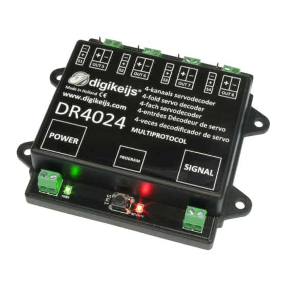
DR4024 Servodecoder
© Copyright 2005 – 2018 digikeijs, the Netherlands. All
rights reserved. No informa3on, images or any part of
this document may be copied without the prior wri4en
permission of Digikeijs.
www.digikeijs.com
® R-Bus, B-Bus are trademarks which are registered in the name of Modelleisenbahn GmbH. XpressNet and RS-Bus is a trademark registered in the name of Lenz
Stand 2019-07-10
DR4024
servo decoder
instruction manual
(2019-07-10)
P 1
Advertisement

Related Manuals for Digikeijs DR4024


Summary of Contents for Digikeijs DR4024
- Page 1 Stand 2019-07-10 DR4024 servo decoder instruction manual (2019-07-10) © Copyright 2005 – 2018 digikeijs, the Netherlands. All rights reserved. No informa3on, images or any part of this document may be copied without the prior wri4en permission of Digikeijs. www.digikeijs.com ® R-Bus, B-Bus are trademarks which are registered in the name of Modelleisenbahn GmbH. XpressNet and RS-Bus is a trademark registered in the name of Lenz...
-
Page 2: General Informa On
ReseBng the DR4024 to Factory Defaults (programming track) Special feature CV programming for control panels which switch off the programming track ReseBng the DR4024 to factory seBngs for Control panels which switch off the programming track Troubleshoo ng, The red LED goes out again even though the programming bu4on was not pressed again. - Page 3 We reserve the right to change the design of the product, soJware and/or firmware without prior no3ce. copyright All Digikeijs manuals and other wri4en instruc3ons supplied and/or downloadable are copyrighted. Duplica3on is not permi4ed without the wri4en permission of Digikeijs.
-
Page 4: Product Overview
With the func3on mapping via CV programming it is possible to realize all imaginable tasks. The DR4024 is a servo decoder with four servo outputs. Each servo output can be programmed to move to four different posi3ons. The DR4024 also has four addi3onal switching outputs which can be used, for exam- ple, for switch polariza3on or for controlling St. -
Page 5: Hardware Overview
DR4024 Servodecoder Stand 2019-07-10 2.3 Hardware Overview Connec3on S1 Servo 1 (Output 1) Connec3on Out 5 (Output 5) Connec3on S2 Servo 2 (Output 2) Connec3on Out 6 (Output 6) Connec3on S3 Servo 3 (Output 3) Connec3on Out 7 (Output 7) - Page 6 Stand 2019-07-10 3.0 Programming If the power input and the signal input of the DR4024 are connected to each other and are connected to the siding of the control unit, the control unit may shut down due to overload. It is be4er to use a switching power supply (DC) with at least 12V 2A for adjustment work and normal opera3on. You should always keep in mind that some servos have a "high"...
- Page 7 The turnout addresses are always assigned by a turnout command!!! Make sure the DR4024 is powered from the decoder's power connector. It is best to use a switching power supply with at least 12V DC output voltage and 2A output power. The signal connec on of the decoder must be connected to the main track output of your control panel! Call up the desired magne3c ar3cle address which the DR4024 is to receive as the start address at the central unit, handset controller, app, etc.
- Page 8 Stand 2019-07-10 3.2 Programming the servo posi ons A-D Make sure the DR4024 is powered from the decoder's power connector. It is best to use a switching power supply with at least 12V DC output voltage and 2A output power.
- Page 9 (For further informa on on CV byte or CV bit programming, please refer to the opera ng instruc ons of your control panel) Now the desired CV value can be wri4en to the DR4024 with the respec3ve func3on Write POM of the central, app or handset controller.
- Page 10 Please note that reading out and programming the DR4024 via the programming track only works if the central unit does not switch off the programming track! Therefore, before a;emp ng programming, check that the green LED next to the power connector is lit. Only if this is the case can the DR4024 be successfully programmed as described in this sec on.
- Page 11 Switch the func3on F0 (light) on and off again to ac3vate the locomo3ve in the control panel. Press the programming bu4on on the DR4024. The red LED now lights up con3nuously and indicates that the DR4024 is in "programming mode".
- Page 12 Wait approx. 30 seconds before powering the DR4024 again and restoring the siding. The DR4024 is now reset to factory seBngs. The POM address was reset to 9999 again and the DR4024 has the magne3c ar3cle address 1 again. By switching the magne3c ar3cle address 1 it can be checked whether the RESET was successful.
- Page 13 LED next to the power connector of the DR4024 indicates whether the programming track always outputs voltage. If this does not light up con nuously, the programming track is switched off. This leads to the DR4024 requiring a different programming or reseDng procedure than usual.
- Page 14 This is absolutely necessary to successfully complete the RESET. AJer approx. 30 seconds the desired connec3on can be restored. The DR4024 is now reset to factory seBngs. The POM address was reset to 9999 again and the DR4024 has the magne3c ar3cle address 1 again. By switching the magne3c ar3cle address 1 it can be checked whether the RESET was successful.
- Page 15 Some central units have the problem that aJer pressing the programming bu4on of the DR4024, the red LED goes out again shortly aJer the programming mode has been ac3vated and the DR4024 automa3cally terminates the programming mode.
- Page 16 DR4024 Servodecoder Stand 2019-07-10 5.0 Connec on examples 5.1 Connec on op ons Power and signal Connec on Supply voltage Signal Connec3on to main track 12-18V DC/AC Power Connec3on to an external Recommended min. power supply 12V DC 2A Recommended for normal opera on and for the POM...
- Page 17 Be sure to observe the polarity (+ and - ) of the DR4102! An incorrect connec3on will destroy the Out x switching out- put on the DR4024! DR4024 PRESET 1 www.digikeijs.com ® R-Bus, B-Bus are trademarks which are registered in the name of Modelleisenbahn GmbH. XpressNet and RS-Bus is a trademark registered in the name of Lenz...
- Page 18 DR4024 Servodecoder Stand 2019-07-10 5.3 Railway crossing with barrier and interchangeable indicators 5.4 Wing signal NL www.digikeijs.com ® R-Bus, B-Bus are trademarks which are registered in the name of Modelleisenbahn GmbH. XpressNet and RS-Bus is a trademark registered in the name of Lenz...
-
Page 19: Servo Installa On And Connec On
DR4024 Servodecoder Stand 2019-07-10 6.0 Servo installa on and connec on Servo connec3on cables should always be kept as short as possible to avoid interference. With long servo cables, always use twisted connec3on cables with a cross-sec3on of at least 0.35 mm² to minimize interference. - Page 20 (this CV can only be wri4en a read out is not possible!) The DR4024 servo decoder has four presets to make programming easier. Each preset configures the DR4020 so that you do not have to change CVs manually. For detailed informa3on on these presets, see page 24.
- Page 21 DR4024 Servodecoder Stand 2019-07-10 CV Defini on Range Value 117 CVs 117-120 each have the same func3on as switching outputs 1-4. 0-179 Switching output 1 (OUT 5) Bits 0-1 sets the switching point for the 'on' posi3on of the assigned switching output.
- Page 22 DR4024 Servodecoder Stand 2019-07-10 CV Defini on Range Value Posi3on A for Servo 2 0-255 Posi3on C for Servo 2 0-255 Posi3on B for Servo 2 0-255 Posi3on D for Servo 2 0-255 Posi3on A for Servo 3 0-255 Posi3on C for Servo 3...
- Page 23 7.1 Funk ons Mapping The following table shows you how to connect the different outputs of the DR4024 module (1-8) to the turnout control panel of your control panel verknüpfen´werden. This can be useful if you want to switch several outputs simultaneously via one key. If you want to switch several outputs in a group with one func on key, then add the values.
- Page 24 DR4024 Servodecoder Stand 2019-07-10 7.2 Presets (Preset 1-4) There are four preset CV sets to make programming easier. These presets are called with the CV47. The seBng in CV47 automa3cally sets some default effects and seBngs. It is not possible to read the CV 47.
- Page 25 DR4024 Servodecoder Stand 2019-07-10 Default seBng 3 (Preset 3) Level crossing with changeable indicators, two barriers and mass simula3on Let your imagina3on run wild by using the presets as a star3ng point on which to build other effects. For example, you can use preset 2 as the basis for a signal that influences the behavior of the locomo3ve: Adjust the func3on mapping so that the outputs switch together with the servos and set the output configura3on so that...
Need help?
Do you have a question about the DR4024 and is the answer not in the manual?
Questions and answers