
Summary of Contents for Pioon H1
- Page 1 Medical Diode Laser System USER MANUAL Model: H1 Wuhan Pioon Technology Co.,Ltd. Version: V1.0 All rights reserved. Revision Date: Mar 12, 2019...
-
Page 2: Table Of Contents
4 INSTALLATION ................23 4.1 Installation Instructions..................23 4.2 Unpacking........................23 4.3 Installation....................... 24 4.4 Packing and Transporting the H1 .................27 4.5 Power Description....................28 5 FIBER AND HANDPIECE ............... 29 5.1 Structure of an Optical Fiber................. 29 5.2 Stripping the Fiber....................30 5.3 Cleaving the Fiber.................... - Page 3 7.1 Preparations......................38 7.2 System boot......................38 7.3 Operational instructions for customized treatment regimens......39 8 TROUBLESHOOTING ..............55 8.1 Notation Type......................55 8.2 Notation mode......................55 8.3 Notation function....................56 8.4 Notation system detection..................57 8.5 Fault Diagnosis and Analysis................57 9 LABELS, SIGNS AND WARNINGS ..........59 10 MAINTENANCE ................
-
Page 4: General
1.1.2 This document is for dentists and office personnel. Introduction H1 , the DIODE LASER DENTAL SYSTEM, from Wuhan PIOON Technology Co., Ltd. (PIOON) assembles the latest semiconductor laser technology available for soft tissue modification and preventative care. The Medical Diode Laser uses GaAlAs diode lasers as energy source. The laser energy is delivered to the surgical area by an optical path transmission system consisting of a flexible fiber connecting the laser source. -
Page 5: Intended Uses
H1 . Intended Uses This PIOON product is intended only for use in the field of dentistry. It is Not recommended to use the product for a purpose for which it was not intended. The H1 is to be used by physicians and trained medical personnel under medical supervision. -
Page 6: Purchase Of Fibers &Tips
Note During use of the H1 device, fiber exposure to oral soft tissue can present bi ological risks. It is advisable to purchase the products that have passed CE/ FDA certification and reduce the biological risks that may occur during the t reatment. - Page 7 For the fiber optics and TIPS categories, refer to the H1 component parts of this manual. For notes on the use of optical fibers, refer to the Chapter 5 of this manual.
-
Page 8: Safety
Proper Use 2.1.1 General The diode laser in the H1 system is a Class 4 laser system. The user must ensure that the device works properly and is in a satisfactory condition before each use. "Proper use" includes following all the instructions for use and ensuring that all inspections and service tasks are performed. - Page 9 Damage from unsuitable accessories The use of other accessories, transformers and lines than those indicated (with the exception of transformers and lines that PIOON sells as replacement parts for internal components) can increase transmission or reduce the electromagnetic immunity of the product.
-
Page 10: Safety Instructions
Europe. Before disassembling and disposing of the product, it must be completely processed according to the section "Disinfection and Sterilization". Additional information can be obtained from PIOON. Safety Instructions 2.2.1 General information A hazard can arise from untrained persons who use the device:... - Page 11 2.2.2 Laser Safety The H1 diode laser system is safe and reliable when used by trained personnels who take proper care in their operation. The H1 diode laser is a Class 4 laser system. Precautions should be taken to avoid accidental exposure to both directed and reflected laser beams.
- Page 12 Surfaces can absorb laser energy. This can cause the surface temperature to rise and ignite the material. Never use the H1 in explosive areas. Never use flammable substances for anaesthesia, preparing the treatment or cleaning and disinfecting the instruments.
- Page 13 Signs in the laser area During operation, the area in which the maximum permissible radiation can be exceeded, the "laser area" must be delimited and identified by a laser warning sign. At the entrances, the operation of the laser must be announced by warning lights and the triangular, yellow laser warning sign.
-
Page 14: Laser System Safety Features
Laser System Safety Features The H1 system provides the following safety features for both operator and patient: 2.3.1 Laser firing The laser is only fired when the READY button is activated and when the footswitch is stepped. The device is in STANDBY mode after the power switch is set to ON position. -
Page 15: Clinical Precautions For Laser Safety
Only practitioners who are thoroughly trained in laser operation procedures, safety precautions and techniques should use H1 units. A thorough understanding of the material presented in this manual is highly recommended before any operation. - Page 16 DO NOT place the footswitch in an area where it may be accidentally pressed. When the laser is not in use, remove the footswitch from the operator's immediate area. Avoid tissue splattering on the working end of the delivery fiber, this will create localized heating, which may cause the fiber tip to char and fail.
-
Page 17: Product Description
It provides the operator with a versatile tool for surgical on oral soft tissue. The H1 utilizes a semiconductor diode with invisible infrared radiation as a laser source and visible red light as indicator light. The laser power is delivered to the treatment area via a flexible fiber, which has a handpiece. - Page 18 USER MANUAL Page 18 of 69...
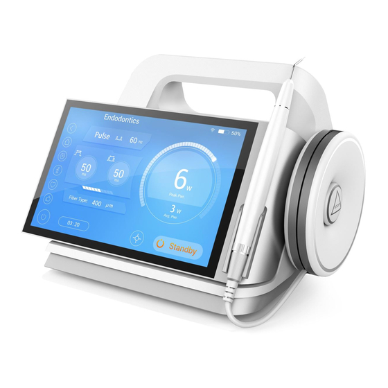
- Page 19 Figure 1 Items ITEM DESCRIPTION Display Display all the operation information Holder Handpiece holder Laser energy is transported through the Fiber fiber Indicator Power(Green)/Notation(red)/Laser(Yellow) Disables the device In the Event of an Emergency Stop Button Emergency Fiber Spool Stores Fiber Handpiece Treatment Handpiece Handle...
-
Page 20: Product Specifications
Lithium ion battery Back-up power Circuit Breaker Master ON/OFF Switch DC Power Connector Connects Power Supply to the Unit Foot switch Connector Port Connects Wired Foot switch to the Unit Remote Interlock Port Connects Interlock to the Unit USB Port Software Update Dental laser handpiece Soft tissue cutting... - Page 21 Magnitudes of the cumulative ≤±20% measurement uncertainty Expected increase ≤±10% measured quantities Positive pulse width 10μs – 999 ms Negative pulse width 10μs – 999 ms Transmission system 200um,400um,600um Timer 0-3600s Adapter input parameters 110-220VAC,50/60Hz Main Unit input parameters 18VDC,5.55A Battery capacity 3350mAh Cooling Method...
-
Page 22: Laser Beam Delivery
SMA905 connectors. The fiber cable should not be bent too much to prevent damage. A fiber holder is provided with the H1 unit to help. The SMA905 connector of a fiber is inserted into laser output port located on the left side of the housing. There is no need to disconnect the fiber frequently from the unit unless it gets too short or requires a replacement. -
Page 23: Installation
Inspect thoroughly the carrying case and components inside for damage and missing items. Unpack all components carefully and verify the presence of all components on the packing slip. Notify Wuhan Pioon Technology Co.,Ltd. immediately if there are any missing items. Page 23 of 69 USER MANUAL... -
Page 24: Installation
Installation Place the main unit of H1 on a suitable table, cart, and shelf top, etc. with a minimum distance of 200 mm to the surroundings. Attach all items in place in the following steps. A. Insert the power cable on the power adapter to the socket which is on the left side of the main unit. - Page 25 Figure 2 The connecting positions of power adapter and remote interlock. D. Carefully take the fiber roller out of package and check for damage. The fiber cable is about 3 meters long. DO NOT allow the fiber to be bended with radius less than 50mm.
- Page 26 G. Attach the other end of the fiber to the SMA socket on the main unit. Remove the protective cap of the SMA905 connector. Hold the metal plug in your hand and do not pull on the fiber. Unscrew the protective cap of the SMA socket on the unit. Note To protect the optical components in the device, the SMA905 socket in the unit must always be closed (with either a fiber cable or a protective cap).
-
Page 27: Packing And Transporting The H1
NEVER pack or transport the unit with the main power on. In the event that the H1 unit needs to be relocated (this does not include moving within an office or a facility), place the system back into its carrying case with the following steps: A. -
Page 28: Power Description
H1 has two power supply modes: external adapter power supply and internal lithium battery. H1 needs away from the wall at least 200 mm to ensure smooth ventilation and facilitate power switch operation. Press the power switch to the ON position to start the device. -
Page 29: Fiber And Handpiece
5 FIBER AND HANDPIECE Structure of an Optical Fiber The structure of an optical fiber normally consists of three main components: Jacket Cladding Quartz/silica fiber or fiber core Figure 5 The structure of an optical fiber. Jacket Jacket is the basic protective cover for the fiber cable and usually is made of a synthetic material that is normally clear or white in color. -
Page 30: Stripping The Fiber
The cladding will burn as protein from the gingiva accumulates on the fiber and will deteriorate the tip. It can fracture if not cleaved once the blackened area has reached 3-4 mm. In this case, the laser emission has to be stopped. It is a good practice to wipe off the tip regularly as you work to avoid accumulation of protein debris. - Page 31 Figure 6 Stripping the jacket. Figure 7 Stripping procedure. Figure 8 Remove 10 to 20mm of the jacket. Page 31 of 69 USER MANUAL...
-
Page 32: Cleaving The Fiber
Cleaving the Fiber As the tip deteriorates, it is more likely to fracture and could fall into the sulcus or a deep periodontal pocket. To avoid this problem, it is prudent to periodically “cleave” the discolored tip. The cleave is made after stripping off the jacket to expose approximately 2cm of bare fiber. -
Page 33: Instruction For Using The Handpiece
Note Make one pass using light but steady pressure Figure 10 Break the fiber against the cleave. Figure 11 Checking the cleave quality by observing the pattern of the aiming beam. Instruction for Using the Handpiece Note Care should be taken to avoid any damage to the jacket when using excessive turning force on the pressure nut. - Page 34 The following sequence is recommended. A. Release the front and mid-ends respectively (Figure 12) B. Put the fiber into the handpiece, adapter and tip; C. Tighten the mid-end adapter; D. Approximately 3–4 in (~7–10 cm) of fiber should protrude E. Strip and cleave fiber (FIGURES 13 and 14) F.
- Page 35 Figure 15 Disconnecting the fiber and tip 5.4.3 Assemble Disposable Fibre Tips on Optional Advanced Fibre Handpiece A. Remove the cap of the Fibre tip B. Remove the protection cap of the handpiece C. Insert the Fibre tip to the handpiece D.
-
Page 36: Change Optional Bleaching And Biostimulation Handpiece
Figure 16 Assemble Disposable Fibre Tips Change Optional Bleaching and Biostimulation Handpiece A. Cleaning the distal end of the fiber connector Fiber Caution: Please make sure to wipe the distal end of the fiber connector and the fiber socket on the machine before inserting! You can use the mixture of 50% aether and 50% grain Alcohol. -
Page 37: Disinfection And Sterilization
6 DISINFECTION AND STERILIZATION The H1 diode laser system is not supplied in sterilized condition. It should be disinfected before use. The following disinfecting procedures are recommended for the following fixtures and attachments to the device: The disposable handpiece tips are supplied non-sterile by the manufacturer and are to be discarded in an infectious waste container after each use. -
Page 38: Operation Procedure
7 OPERATION PROCEDURE Note There are three output modes: continuous, pulse and single pulse in the H1 diode dental laser. The operator should choose a suitable protocol according to the patient's condition and treatment. If the control device, regulator or is not used or operated according to the prescribed method, dangerous radiation will be produced, which will cause injury and damage to people and equipment. -
Page 39: Operational Instructions For Customized Treatment Regimens
Operational instructions for customized treatment regimens 7.3.1 Turn on the device and enter the login page. Put the PIN code. Note The login password is 4 digits. The login password is owned by the authorized person, and the unauthorized person may not use the device without permission. Figure17 Login page Page 39 of 69 USER MANUAL... - Page 40 7.3.2 Enter the password into the home page (Figure 18), select the treatment. Figure 18 Home page The meaning of different button are as follow: Button / Label Meaning Choose the suitable power and output mode follow your Customize need. Procedures Official protocols;...
- Page 41 Operation times: it will be counted once when a protocol Total Treatment emitting duration last more than 10 seconds. Video: Videos can be played and copied to the device. Contact way Setting 7.3.3 Click "Customize" to enter the user-defined interface and create a new protocol.
- Page 42 Indicator light: When the indicator light shows red, it’s on; When it shows white, it’s off. Shows the time duration of the treatment, can be also set as a count- down mode. Laser emitting Indicator: Parameters can be set at the standby mode, parameters can’t be changed at the ready mode,...
- Page 43 Figure 20 Emitting Mode Select Interface B. Click on "Standby", into the "Ready" mode. Only in this page you can step the footswitch to emit laser. (Figure 21) Figure 21 Customize Running Interface Page 43 of 69 USER MANUAL...
- Page 44 7.3.4 Click on "Procedures" in the home page (Figure 18) and enter the protocol select interface. (Figure 22) Figure 22 Protocols select page A. Select the required categories and enter the Solutions List interface. (Figure 23) USER MANUAL Page 44 of 69...
- Page 45 Figure 23 Protocols List Interface B. Select a specific protocol, you can enter the operation interface .(example: Figure Figure 24 Protocol operation interface Page 45 of 69 USER MANUAL...
- Page 46 7.3.5 In the treatment interface (example: Figure 19), users can change the parameters according to actual needs, like the treatment time, laser power, and the emitting mode. Users can save the changed protocol by click “♥”, inset the name and confirm to save it, for the quick use next time.
- Page 47 Figure 26 "Favorites" Interface 7.3.6 Enter the video list interface (Figure 27) from the home page (Figure 18). When playing video, sliding up and down on the left half of the screen can adjust the brightness of the screen, sliding up and down on the right half of the screen can adjust the voice, sliding in the left and right direction of the screen can quickly adjust the playing progress.
- Page 48 Figure 27 Video List Page 7.3.7 Click "Settings" on the home page (Figure 18), enter the administrator settings interface. USER MANUAL Page 48 of 69...
- Page 49 Figure 28 Adjust the current user mode page A. Expert mode Adjust the current user mode, turn it on to expert mode, turn it off to novice mode, and the top status bar will hint which mode it is in real time. (Figure 28) Introduction of novice mode and expert mode: In expert mode, users can modify the parameters of the official protocol when they enter the official scheme.
- Page 50 Figure 30 adjust the indicating light brightness interface C. Wifi Page of connecting Wifi; click “Wifi”,click “ON” can connect to a wireless network. After opening Wifi, you can search the surrounding wifi, click to enter the password. If the password is correct, wifi will connect to the wireless network. Long press to forget the wifi password, after forgetting, you can enter the password input interface again.
- Page 51 Figure 31 Wifi connection interface D. Users: multi-user management interface, providing the function of creating new Users and modifying Users. (figure 32) Super admin can modify, create and delete user information, other users can only view the list of users, cannot create a new user and modify or delete the user name and password.
- Page 52 Figure 32 multi-user management interface E. Customizations: Set brightness, sound size and unit interface. (Figure 33) Figure 33 setting brightness, sound size and unit interface F. Language: Language, set up the software language, currently only support English. (Figure 34) USER MANUAL Page 52 of 69...
- Page 53 Figure 34 language setup interface G. Date&Time: Time setting (Figure 35). Figure 35 Time setting interface Page 53 of 69 USER MANUAL...
- Page 54 H. DEVICE INFO: Device parameter information interface, you can view the device information. (Figure 36) Figure 36 device information interface USER MANUAL Page 54 of 69...
-
Page 55: Troubleshooting
8 TROUBLESHOOTING Notation Type The system provides five notation prompts, namely: High temperature notation Remote interlock notation Foot switch notation Laser notation Fiber notation Battery power notation All of the above notations are technical notations. When the notation occurs, the user to do the appropriate treatment according to the priority of the notation to prevent personnel and device damage. -
Page 56: Notation Function
When the notation is released, the red light turns off. Notation function The Medical Diode Laser monitors the operating status of the system in real time. Through Sounds, indicators, and graphical warning signs alert user happened unusual events and interrupting the laser outputting. Notation Triggering conditions Notation release method... -
Page 57: Notation System Detection
Notation system detection The user can determine whether the notation system is normal by self-test: For example, if the user unplug the remote interlock, the system will sound, notation indicator, graphical warning signs and other notation status. After verifying the notation system is normal, please restore the remote interlock. - Page 58 the laser is outputting. 1. Clean the glass lens with a paper 1. The glass lens of towel; Laser power handpiece is with dust or other 2. Calibrate the laser power according to attenuation dirt; the instructions 2. Laser attenuation; 3.
-
Page 59: Labels, Signs And Warnings
9 LABELS, SIGNS AND WARNINGS Product identification and packaging instruction are in line with IEC60825-1-2014, EN ISO 15223-1: 2012 and other related requirements. Product identification and packaging used in graphics, symbols are as follows: Graphics / symbols Meaning Position Optical Fiber &... - Page 60 Graphics / symbols Meaning Position Pull the handpiece up Right side of the main unit Left back side of the main Product nameplate unit Serials number Nameplate Instruction manual Nameplate Manufacture date Nameplate Manufacturer Nameplate B Type Nameplate Non-recyclable Nameplate European Representative...
-
Page 61: Maintenance
10 MAINTENANCE WARNING This product is a Class 4 laser product. During use and maintenance, do not look into the laser or direct beam to avoid irreversible damage to the eyes. It is strongly recommended that users carefully read the instructions to avoid the damage on the human body and device that caused by the possible harmful laser radiation. -
Page 62: Routine Inspection
10.2 Routine Inspection Clinicians can routinely check the device under the guidance of the dealer or on their own to ensure that the device work properly. The general check contents are as follows: 1)Whether the safety device is normal: Safety interlock, foot switch, optical switch, emergency stop switch;... -
Page 63: Calibration Schedule
themselves in order to avoid the risk of laser radiation. Calibration records shall be completed by the calibration engineer and kept by the Marketing Department. WARNING Please carry out the calibration of the device under the guidance of the authorized personnel of the company or the designated dealer. During the calibration process, please wear eye protection to avoid possible harmful laser radiation damage to personnel and device. -
Page 64: Limited Warranty
11 LIMITED WARRANTY The diode laser Medical system, H1, is warranted to be free from defects in material and workmanship for a period of 12 months from the date of selling. Handpieces, fibers and other accessories are warranted to be free from defects in material and workmanship for a period of 12 months from the date of selling. -
Page 65: Electromagnetic Compatibility
Medical system should be observe to verify normal operation in the configuration in which it will be used. Note Wuhan PIOON Technology Co.,Ltd. can not guarantee that accessories, lines and transformers not delivered by Wuhan PIOON Technology Co.,Ltd. will correspond with EMC requirements of EN 60601-1-2. Accessory part/name Length/dimensions Footswitch with cable <3.0m... -
Page 66: Emitted Electromagnetic Interference
12.1 Emitted electromagnetic Interference The diode laser Medical system is intended for use in the electromagnetic environment specified below. The customer or the user of the diode laser Medical system should assure that it is used in such an environment. Emissions test Compliance Electromagnetic environment –... - Page 67 Conducted RF 3 Vrms Portable and mobile RF communications IEC 61000-4-6 150 kHz to 80 MHz equipment should be used no closer to any 3 Vrms part of the diode laser Medical system, 150 kHz to 80 MHz including cables, than the recommended separation distance calculated from the Radiated RF 3 V/m...
-
Page 68: Recommended Safe Distance
12.3 Recommended Safe Distance The diode laser Medical system is intended for use in an electromagnetic environment in which radiated RF disturbances are controlled. The customer or the user of the diode laser Medical system can help prevent electromagnetic interference maintaining minimum distance... -
Page 69: Contact
13 CONTACT The contact information of Model H1 is: The Manufacturer: Wuhan Pioon Technology Co.,Ltd., 3rd Fl, Zhiye Building, #323 Minzu Ave., Great Wall Innovation Science Address: Park, Wuhan 320223, China Contact person: Ms. Min Liao Email: PIOON@PIOONorp.com.cn Website www.PIOON.com...
Need help?
Do you have a question about the H1 and is the answer not in the manual?
Questions and answers