Advertisement
Quick Links
0.25
Futura Book 24Pt
LUXOMAT
1:4
1.
0.5
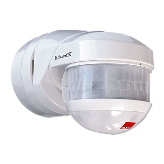
Installation and Operating Instruction for motion detctor LUXOMAT
0.25
Futura Book 24Pt
1. Product information
1:4
1.
„ Motion detector with 130°, 230° or 280° detection area
and anti-creep zone
0.5
0.25
„ Mechanical range adjustment
Futura Book 24Pt
„ Adjustable ball head
„ Dynamic adaption of the follow-up time depending on
direction of movement
„ Simple mounting thanks to plug-in base
„ Wall, ceiling and corner mounting
„ Immediate operation using factory settings
„ Additional functions can be set up using the optional
remote control
2. Operation
Motion detectors switch the light automatically depending on
movement and ambient brightness.
If the ambient light is below the switch-on threshold, a movement
activates the lighting.
The lighting is switched off after the follow-up time has elapsed
and no movement detected.
3. Safety information
Work on the 110-240 V mains supply may only be carried
!
out by qualified professionals or by instructed persons
under the direction and supervision of qualified skilled
electrical personnel in accordance with electrotechnical
regulations.
!
Disconnect supply before installing!
!
This device is not suitable for disconnection.
The total number of switchable loads is limited due to high
!
inrush currents of electronic ballasts and LED drivers. In
case of a large number of connected loads please use an
external contactor.
For all connected loads, proper interference suppression is
!
obligatory
(we recommend to use our arc extinction kits).
4. Mounting and aligning the detector
Recommended mounting height: 2.5 m
Detector can be plugged into the socket
10°
2
1) Fix the mounting socket on a solid plane using two screws
(please take care with cable introduction).
2) Press connection socket onto mounting socket. For a better
adjustment, the connection socket can be rotated through
10°.
®
180°
45°
The detection range or the detection area can be modified by
rotating the detector head vertically and horizontally (detector head
horizontal = max. detection range)
5. Mounting options
Wall mounting
Outside / inside corner mounting using corner socket (accesso-
ry, outer corner socket included in delivery RC-plus next 280)
6. Mounting locations
> 1m
7. Cable introduction
1
1
2
1)
from above
2) from below
3) from wall side (please use an
additional sealing, not included in
delivery)
4) terminals
15s 30s
(see wiring diagrams, pt. 15)
RC-plus next
RC-plus next
®
10°
Ceiling mounting
1) Mount the
device at
a weath-
er-protect-
ed place.
2) Follow the installation standards.
4
1 :
1 .
5
0 .
2 5
0 .
P t
2 4
o k
o
B
r a
t u
F u
3) Minimum distance
to the switched
light, frontally or
laterally to device:
1m
4) Do not mount a
light source below
the detector.
1
4
8
4
1,5 2 3 5 6 7 10
8. Self-test cycle
The product enters an initial 60-second self-test cycle when the sup-
ply is first connected. During this time the device does not respond
to movement.
9. Mechanical adjusting means and potentiometers /
LED arrangement
A
B
C
A
B
C
4
1 :
1 .
5
0 .
2 5
0 .
RC-plus next 230
RC-plus next 130
P t
2 4
o k
o
B
r a
t u
F u
A Range B Follow-up time C Switch-on threshold
Remove the cap below the lens in order to access the mechanical
adjusting means and potentiometers.
Mechanical range adjustment (A)
-
+
Depending on the version, the RC-plus next comprises a different
number of detection zones (130°: 1 zone, 230°: 2 zones, 280°:
3 zones). The detection range within these zones can be adjusted
individually for each zone. The number of mechanical adjusting
means corresponds to the number of detection zones.
+: approx. 20 m, –: approx. 5 m (mounting height 2.5m)
Test mode / Follow-up time / Pulse (B)
1
4
8
16
The test mode is for determining the detection area. Upon each
detected movement the light is switched on.
15s 30s
1,5 2 3 5 6 7 10
The follow-up time is a time period which starts upon detected move-
ment and which defines the duration for the connected load to stay
on. The duration can be chosen between 15s and 16 min.
When PULSE is selected, a pulse of one second is sent upon detect-
ed movement, followed by a pause of nine seconds.
Switch-on threshold (C)
The different symbols represent different LUX values, the black
moon representing night operation (light is switched on only when
it is dark). The sun represents day and night operation, the light
evaluation is inactive.
10. Factory settings
&
„TEST"
Upon delivery, the potentiometers are set to "SUN" and "TEST". This
means, that the factory settings are active and the detector is ready
for operation. The factory settings are as follows:
Follow-up time: 3 min.
3
Switch-on threshold: 20 Lux
16
12
EN
A
B
C
A
A
A
RC-plus next 280
LED
12
Advertisement

Related Manuals for B.E.G. LUXOMAT RC-plus next Series


Summary of Contents for B.E.G. LUXOMAT RC-plus next Series
- Page 1 0.25 Futura Book 24Pt RC-plus next LUXOMAT ® Installation and Operating Instruction for motion detctor LUXOMAT RC-plus next 0.25 ® Futura Book 24Pt 1. Product information 10° 8. Self-test cycle „ Motion detector with 130°, 230° or 280° detection area The product enters an initial 60-second self-test cycle when the sup- and anti-creep zone ply is first connected.
- Page 2 In case the lighting is switched-on for more than 90 minutes, it will 11. Range at a mounting height of 2.5 m; 16. Technical data be switched off for a short time in order to allow for measuring the Minimum mounting height 2.00 m ambient luminosity (daylight).
- Page 3 The function being activated, the detector works like a 19. Settings with remote control (optional) Alarm function photoelectric switch. The light is switched on when the activation/deactivati- light value passes below the switch-on threshold Settings with remote control overwrite the settings by the on (see section 21) (switch-on delay 1 min).
Need help?
Do you have a question about the LUXOMAT RC-plus next Series and is the answer not in the manual?
Questions and answers