Table of Contents
Advertisement
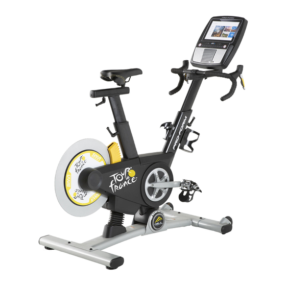
Model No. PFEVEX71919.0
Serial No.
Write the serial number in the space
above for reference.
USER'S MANUAL
Serial Number
Decal
CUSTOMER SERVICE
UNITED KINGDOM
Call: 0330 123 1045
From Ireland: 053 92 36102
Website: iconsupport.eu
E-mail: csuk@iconeurope.com
Write:
ICON Health & Fitness, Ltd.
Unit 4, Westgate Court
Silkwood Park
OSSETT
WF5 9TT
UNITED KINGDOM
AUSTRALIA
Call: 1800 993 770
E-mail: australiacc@iconfitness.com
Write:
ICON Health & Fitness
PO Box 635
WINSTON HILLS NSW 2153
AUSTRALIA
CAUTION
Read all precautions and
instructions in this manual before
using this equipment. Keep this
manual for future reference.
iconeurope.com
Advertisement
Table of Contents

Related Manuals for Pro-Form Le Tour De France PFEVEX71919.0


Summary of Contents for Pro-Form Le Tour De France PFEVEX71919.0
- Page 1 Model No. PFEVEX71919.0 Serial No. Write the serial number in the space above for reference. USER’S MANUAL Serial Number Decal CUSTOMER SERVICE UNITED KINGDOM Call: 0330 123 1045 From Ireland: 053 92 36102 Website: iconsupport.eu E-mail: csuk@iconeurope.com Write: ICON Health & Fitness, Ltd. Unit 4, Westgate Court Silkwood Park OSSETT...
-
Page 2: Table Of Contents
TABLE OF CONTENTS WARNING DECAL PLACEMENT ............. . .2 IMPORTANT PRECAUTIONS . -
Page 3: Important Precautions
IMPORTANT PRECAUTIONS WARNING: To reduce the risk of burns, fire, electric shock, or injury to persons, read all important precautions and instructions in this manual and all warnings on your training bike before using your training bike. ICON assumes no responsibility for personal injury or property damage sustained by or through the use of this product. -
Page 4: Before You Begin
BEFORE YOU BEGIN Congratulations for selecting the revolutionary reading this manual, please see the front cover of this PROFORM LE TOUR DE FRANCE training bike. manual. To help us assist you, note the product model ® ® The LE TOUR DE FRANCE training bike is unlike any number and serial number before contacting us. -
Page 5: Part Identification Chart
PART IDENTIFICATION CHART Use the drawings below to identify the small parts needed for assembly. The number in parentheses below each drawing is the key number of the part, from the PART LIST near the end of this manual. The number following the key number is the quantity needed for assembly. -
Page 6: Assembly
ASSEMBLY • Assembly requires two persons. • In addition to the included tool(s), assembly requires the following tools: • Place all parts in a cleared area and remove the one Phillips screwdriver packing materials. Do not dispose of the packing materials until you finish all assembly steps. - Page 7 3. If there are shipping screws in the Rear Stabilizer (23), remove and discard them. Attach the Rear Stabilizer (23) to the Base (1) with two M10 x 58mm Screws (74). 4. Using a plastic bag to keep your fingers clean, apply some of the included grease to the sides Grease of the channel on the top of the Saddle Post (3).
- Page 8 5. Note: You can attach your own saddle to the Saddle Carriage (4) if desired. Loosen the attachment hardware (not shown) beneath the Saddle (5), and remove the Saddle. Then, attach your own saddle and retighten the attachment hardware. Orient the Saddle Carriage (4) as shown. Loosen the Adjustment Handle (47), and slide the Saddle Carriage (4) into the Saddle Post (3).
- Page 9 7. Have a second person hold the Handlebar (7) near the Handlebar Carriage (105). Locate one of the remaining wire ties (F) in the Handlebar Carriage (105). Tie the indicated end of the wire tie to the Right Extension Wire (107). Then, pull the other end of the wire tie until the Right Extension Wire is routed through the Handlebar Carriage.
- Page 10 9. Have a second person hold the Console (9) near the Handlebar Carriage (105). Connect the console wires to the Main Wire (68) and to the Extension Wires (107, 108); make sure to connect the console wire that has an 107, 108 “L”...
- Page 11 12. Note: You can attach your own pedals if desired. Identify the Right Pedal (62). Using the included flat wrench tool, firmly tighten the Right Pedal (62) clockwise into the Right Crank Arm (64). Firmly tighten the Left Pedal (not shown) counterclockwise into the Left Crank Arm (not shown).
-
Page 12: How To Use The Training Bike
HOW TO USE THE TRAINING BIKE HOW TO PLUG IN THE POWER ADAPTER The Incline System IMPORTANT: If the training bike has been exposed The training bike can incline and decline up to 20 per- to cold temperatures, allow it to warm to room tem- cent to realistically simulate outdoor terrain. - Page 13 HOW TO ADJUST THE GEOMETRY OF THE How to Adjust the Saddle Post TRAINING BIKE For effective train- The training bike can be adjusted to match the geom- ing, the saddle etry of your road bike to promote correct form and to should be at the ensure proper training of the muscles.
- Page 14 How to Adjust the Handlebar Carriage HOW TO USE THE PEDALS To adjust the To use the pedals, position of the insert your shoes handlebar car- into the toe cages, riage (K) to match and pull the ends of your road bike, the toe straps (N).
- Page 15 CONSOLE DIAGRAM FEATURES OF THE CONSOLE When you use the manual mode of the console, you can change the incline (resistance) of the training bike The advanced console offers an array of features and change gears with the touch of a button. designed to make your workouts more effective and enjoyable.
- Page 16 HOW TO TURN ON THE CONSOLE HOW TO USE THE TOUCH SCREEN The included power adapter must be used to operate The console features a tablet with a full-color touch the training bike. See HOW TO PLUG IN THE POWER screen.
- Page 17 HOW TO SET UP THE CONSOLE To change console settings, see page 23. To connect to a wireless network, see page 24. To Before you use the training bike for the first time, set use the sound system, see page 25. up the console.
- Page 18 4. Change gears as desired. 6. Wear a heart rate monitor and measure your heart rate if desired. Note: The training bike simulates gears; there are no actual gears. You can wear an optional heart rate monitor to measure your heart rate. For more informa- Change gears by pressing the buttons on the tion about the optional heart rate monitor, see right shifter.
- Page 19 HOW TO USE A MAP WORKOUT OR AN ONBOARD To draw your own map for a workout, see HOW TO WORKOUT CREATE A DRAW-YOUR-OWN-MAP WORKOUT on page 21. 1. Touch the screen or press any button on the console to turn on the console. When you select a workout, the screen will show an overview of the workout that includes details See HOW TO TURN ON THE CONSOLE on...
- Page 20 During some workouts, the incline will automatically When the workout comes to an end, a workout adjust to the incline levels programmed for the summary will appear on the screen. If desired, you workout. can publish your results using one of the options on the screen.
- Page 21 HOW TO CREATE A DRAW-YOUR-OWN-MAP If you make a mistake, touch Undo on the left side WORKOUT of the screen. 1. Touch the screen or press any button on the The screen will display the elevation and distance console to turn on the console. statistics for your workout.
- Page 22 HOW TO USE AN IFIT WORKOUT 4. Select an iFit workout that you have previously added to your schedule on iFit.com. To use an iFit workout, the console must be connected IMPORTANT: Before iFit workouts will load, you to a wireless network (see HOW TO CONNECT TO A must add them to your schedule on iFit.com WIRELESS NETWORK on page 24).
- Page 23 HOW TO CHANGE CONSOLE SETTINGS 4. Customize the unit of measurement and other settings. IMPORTANT: Some of the settings and features described may not be enabled. Occasionally, a To customize the unit of measurement, the time firmware update may cause your console to function zone, or other settings, touch Equipment Settings, slightly differently.
- Page 24 HOW TO CONNECT TO A WIRELESS NETWORK Note: You must have your own wireless network and an 802.11b/g/n router with SSID broadcast To use iFit workouts and to use several other features enabled (hidden networks are not supported). of the console, the console must be connected to a wireless network.
- Page 25 HOW TO USE THE SOUND SYSTEM THE OPTIONAL CHEST HEART RATE MONITOR To play music or audio books through the console Whether your sound system while you exercise, plug a 3.5 mm male goal is to to 3.5 mm male audio cable (not included) into the burn fat or to jack on the console and into a jack on your personal strengthen your...
-
Page 26: Maintenance And Troubleshooting
MAINTENANCE AND TROUBLESHOOTING HOW TO MAINTAIN THE TRAINING BIKE person plug in the power adapter. Continue holding the reset button until the console turns on. When the reset Regular maintenance is important for optimal operation is complete, the console will turn off and then performance and to reduce wear. -
Page 27: Exercise Guidelines
EXERCISE GUIDELINES Aerobic Exercise—If your goal is to strengthen your WARNING: cardiovascular system, you must perform aerobic Before beginning this exercise, which is activity that requires large amounts or any exercise program, consult your physi- of oxygen for prolonged periods of time. For aerobic cian. - Page 28 SUGGESTED STRETCHES The correct form for several basic stretches is shown at the right. Move slowly as you stretch; never bounce. 1. Toe Touch Stretch Stand with your knees bent slightly and slowly bend forward from your hips. Allow your back and shoulders to relax as you reach down toward your toes as far as possible.
-
Page 29: Part List
PART LIST Model No. PFEVEX71919.0 R0819A Key No. Qty. Description Key No. Qty. Description Base Board Bracket Frame Standoff Saddle Post Crank/Torque Pulley Saddle Carriage M4 Washer Saddle Magnet Handlebar Post Crank Screw Handlebar Bearing Tray Push Nut Console Frame Bushing Upper Shield Pivot Axle Left Shield... - Page 30 Key No. Qty. Description Key No. Qty. Description Reed Switch/Wire #8 x 1/2" Screw Crank Hub #8 x 1/2" Bright Screw Crank Spacer M8 x 15mm Round Head Screw M8 Locknut M4 x 10mm Screw Handlebar Carriage M4 x 14mm Screw M8 x 20mm Screw M8 x 30mm Screw Right Extension Wire...
-
Page 31: Exploded Drawing
EXPLODED DRAWING Model No. PFEVEX71919.0 R0819A... -
Page 32: Ordering Replacement Parts
ORDERING REPLACEMENT PARTS To order replacement parts, please see the front cover of this manual. To help us assist you, be prepared to provide the following information when contacting us: • the model number and serial number of the product (see the front cover of this manual) •...
Need help?
Do you have a question about the Le Tour De France PFEVEX71919.0 and is the answer not in the manual?
Questions and answers