Table of Contents
Advertisement
Quick Links
Advertisement
Table of Contents
Troubleshooting

Related Manuals for Envipco FLEX Series


Summary of Contents for Envipco FLEX Series
- Page 1 FLEX Series Service Manual March 16, 2016...
-
Page 3: Table Of Contents
Contents List of Figures ..........i Chapter 1 Introduction & Safety ......... 1-1 Foreword ..................1-1 1.2 Symbols Used ................1-1 1.3 Users ....................1-1 1.3.1 Customer ..............1-2 1.3.2 Sponsor ................1-2 1.3.3 Machine Attendants ............ 1-2 1.3.4 Service Technician............1-2 1.4 Safety precautions .............. - Page 4 Contents Chapter 3 Hardware Components ......3-1 3.1 Introduction ..................3-1 3.2 Cabinet ..................3-3 3.2.1 Door Interlock ............. 3-3 3.2.2 Bin Full Sensor ............3-4 3.2.3 FLEX and FLEX Tri Cabinets ........3-4 3.2.4 FLEX HDS Cabinet ............ 3-5 3.3 Sensor Scanner ................
- Page 5 4.2 Shop Mode ................. 4-1 4.3 Service Mode ................4-2 4.3.1 Starting Service Mode ..........4-2 4.3.2 Using the Technician Interface ........4-3 4.3.3 Exiting Service Mode ..........4-5 4.4 Diagnostic Program ..............4-6 4.4.1 Processes Tab.............. 4-6 4.4.2 Misc Tab ..............4-8 4.4.3 Main Tab ..............
- Page 6 Contents Chapter 6 Troubleshooting & Repairs ....... 6-1 6.1 Introduction ..................6-1 6.2 FLEX’s Error Messages ............. 6-1 6.3 VFD Status Messages ..............6-5 6.4 Troubleshooting Other Conditions ..........6-6 6.4.1 Display Not Functional ..........6-6 6.5 Repairs ..................6-6 6.5.1 Swapping an RVM Controller ........
-
Page 7: List Of Figures
List of Figures Laser Compliance Label ............... 1-4 Laser Danger Label................1-5 High Voltage Warning Label............... 1-5 Safety Label Locations ................. 1-5 Door Interlock Label ................1-7 Compactor Motor Disconnect Label ............ 1-8 Moving Parts Warning Label ..............1-8 Moving Parts Warning Label Location .......... - Page 8 List of Figures Diagnostics - Processes Tab ..............4-6 Diagnostics - Miscellaneous Options Tab ..........4-8 Diagnostics - Main Tab ................. 4-9 Diagnostics – Untra-48Tab ..............4-10 Diagnostics – RS-485 Tab ..............4-13 Diagnostics - Config Tab ..............4-14 MC1 Sensors..................4-17 MC5 Sensors..................
-
Page 9: Introduction & Safety
Warning! Service and most maintenance tasks are the sole responsibility of Envipco and should only be performed by Envipco or other authorized maintenance personnel. 1.2. Symbols Used Warning symbols indicate the levels of danger involved with some of the procedures described in this manual. -
Page 10: Customer
The sponsor is FLEX responsible for maintaining a list of redeemable containers (the “bar code table”), notifying Envipco of updates to the bar code table, and requesting custom messages appearing on the and printed vouchers. Warning! -
Page 11: Safety Precautions
Safety precautions 1.4. Safety precautions Safety for customers, machine attendants, and service technicians is paramount in the design and . Read this manual carefully, and follow all of the safety rules continuing development of the FLEX that it provides. Warning! . -
Page 12: Safety Labels
When performing the scanner maintenance tests, it is possible to be exposed to HeNe (633 nm) laser radiation levels up to Class IIIa. This maintenance test is only performed by Envipco service technicians. The label in Figure 1-2 gives the appropriate warning. Figure 1-3 shows the location of... -
Page 13: Laser Danger Label
Safety labels Laser Danger Label FIGURE 1-2. Laser Radiation When Open and Interlock Failed or Defeated. AVOID DIRECT EYE EXPOSURE High Voltage Warning Label FIGURE 1-2.1. Safety Label Locations FIGURE 1-3. DOOR INTERLOCK HIGH VOLTAGE LABEL WARNING LABEL LASER DANGER LABEL FLEX DFF FLEX DFF/GDS... - Page 14 Chapter 1 Introduction & Safety LASER DANGER LABEL FLEX HDS...
-
Page 15: Electrical Safety
Safety labels HIGH VOLTAGE WARNING LABEL DOOR INTERLOCK LABEL FLEX HDS 1.5.2. Electrical safety , the safety interlock switches off the power to the motors. When you open the doors of the FLEX However, the machine itself still has power. The door interlock label in Figure 1-4 gives the appropriate caution. -
Page 16: Mechanical Safety
Chapter 1 Introduction & Safety contains high voltage components in the Motor Control Box. Therefore, it has a label FLEX warning of its danger. Figure 1-5 shows the warning. See Figure 1-3 for the exact location of this label. Warning! Always turn the Compactor Motor Disconnect Switch to the position before performing service on the FLEX... -
Page 17: Moving Parts Warning Label Location
Safety labels Moving Parts Warning Label Location FIGURE 1-7. Keep Hands Out Warning Two pinch-point labels warn that moving parts can injure your hands. Figure 1-8 shows the pinch- point label. Figure 1-9 shows where these labels are located. Pinch Point Label FIGURE 1-8. - Page 18 Chapter 1 Introduction & Safety Pinch Point/Keep Hands Away Label Locations FIGURE 1-9. Right Access Panel FLEX DFF FLEX DFF/GDS Left Access Panel FLEX DFF FLEX DFF/GDS 1-10...
- Page 19 Safety labels Intake Conveyor FLEX DFF FLEX DFF/GDS FLEX HDS Side Glass Diverter FLEX DFF/GSD ONLY 1-11...
- Page 20 Chapter 1 Introduction & Safety FLEX HDS ONLY REAR PANEL PINCH POINT WARNING LABEL FLEX HDS ONLY LEFT PANEL KEEP HANDS AWAY WARNING LABEL 1-12...
- Page 21 Safety labels FLEX HDS ONLY RIGHT PANEL KEEP HANDS AWAY WARNING LABEL 1-13...
- Page 22 Chapter 1 Introduction & Safety KEEP HANDS AWAY WARNING LABEL PINCH POINT WARNING LABEL FLEX HDS ONLY FRONT 1-14...
-
Page 23: Chapter 2 Specifications
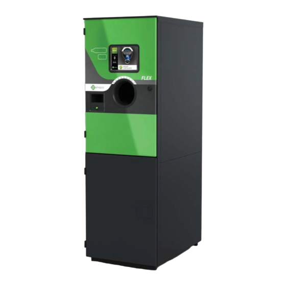
Chapter 2 Specifications 2.1. General Specifications is Envipco’s series of high speed reverse vending machines. There are three main configurations: FLEX & & ) and FLEX DUAL ALUMINUM FLEX TRI ALUMINUM GLASS flex hds. 2.1.1. Serial Label The configuration of a is listed on its serial label. -
Page 24: Flex Configuration
FLEX Configuration FIGURE 2-2 Display Receipt Chute In-Feed Payment Button Commodity Storage... -
Page 25: Flex Specifications
General Specifications 2.1.3. FLEX Specifications Table 2-1 lists the specifications for the two configurations of the : the FLEX FLEX DUAL FLEX TRI FLEX HDS FLEX Specifications TABLE 2-1 FLEX Dual FLEX HDS FLEX Tri Overall 69.5"h × 23.6"w × 34.5"d 75.48"h ×... -
Page 26: Power Requirements
Chapter 2 Specifications 2.1.4. Power Requirements Table 2-2 shows the power requirements by model. All models receive single-phase power from the outlet, regardless of whether the outlet is three-phase or single-phase. RVM Power Requirements TABLE 2-2 Product Voltage (VAC) Amperage (A) Frequency (Hz) 208/240 1-phase... -
Page 27: Container Accounting
When done redeeming containers, the customer presses the payment button. The printer prints a voucher. 2.2.2. Container Accounting contains a list of acceptable beverage containers in a bar code database. Envipco gathers FLEX this information from the machine’s sponsor and beverage distributors and makes updates to the machines when necessary. - Page 28 Chapter 2 Specifications Notes:...
-
Page 29: Hardware Components
Chapter 3 Hardware Components 3.1. Introduction This section describes all of the hardware components of the Series. See Figure 3-1 for a FLEX view of the main components of the and Figure 3-2 for a view of the main components of FLEX FLEX HDS FLEX Main Components... -
Page 30: Flex Hds Main Components
Chapter 3 Hardware Components FLEX HDS Main Components FIGURE 3-2. Front Loading FLEX HDS RVM CONTROLLER Sensors/Display Compactor 1 Compactor 2 Printer AC Box Location Door Removed AC Box not shown... -
Page 31: Cabinet
RVM CONTROLLER AC Box Location Front Panel Removed AC Box not shown 3.2. Cabinet ’s cabinet is comprised of a top cabinet and two commodity storage cabinets below. The top cabinet houses the ’s In-Feed, Sorting Cylinder, compactors, and all of its electronic and electrical components. -
Page 32: Bin Full Sensor
Cabinet Chapter 3 Hardware Components 3.2.2. Bin Full Sensor To prevent commodity from overflowing the bins, each lower cabinet has a bin full sensors. If a sensor detects that a bin is full, the machine stops collecting the commodity whose bin is full. If the machine only collects one type of container, and its bin is full, the machine goes out of service and displays an appropriate message. -
Page 33: Sensor Scanner
Chapter 3 Hardware Components FLEX Cabinet FIGURE 3-3 Levelers and Casters (1 of 4) 3.2.4. FLEX TRI Cabinet s have four front doors: two on the bottom that covers the commodity bins and FLEX TRI RVM two on the top. An access panel on each side of the machine facilitates machine maintenance and service. - Page 34 Sensor/Load Cell/Camera/Laser Infeed Sensor/Scanner (Right Side View) FIGURE 3-4. Display Sensor PET Emitter Retro Reflector (1 of 5) Sensor Clear material Light Curtain Sensor Infeed Sensor/Scanner Tunnel (Left Side View) FIGURE 3-5. Scanners Scanner Multiplexer (Mux) Sensor PET Receiver...
-
Page 35: Scanners
Chapter 3 Hardware Components 3.3.1. Scanners The Sensor Display has two (2) scanners mounted on the top side. The two (2) scanners are wired to a multiplexer ( ) board that coordinates the flow of data to and from the software, so they are all working together as if it was one larger scanner. -
Page 36: Materials Sensors
Sensor/Load Cell/Camera/Laser 3.3.3. Materials Sensors By the time a container reaches the end of the conveyor, it passes the retro-reflector materials sensors. As shown in Figure 3-4 on page 3-6, the emitter is lined up on the left side of the Scanner Display, and the reflector are across from the emitter on the right side of the Scanner Display. -
Page 37: Load Cell Flex
Chapter 3 Hardware Components Load Cell Flex FIGURE 3-7. SORTING CYLINDER LOAD CELL Load Cell Flex HDS FIGURE 3-8. LOAD CELL ASSEMBLY ULTRASONIC BIN FULL SENSORS... -
Page 38: Camera/Laser
Sensor/Load Cell/Camera/Laser Camera/Laser FIGURE 3-9. CAMERA RVM CONTROLLER LASER LINE GENERATOR 3-10... -
Page 39: Sorting Cylinder
Chapter 3 Hardware Components 3.4. Sorting Cylinder At the rear of the conveyor is the Sorting Cylinder assembly. The conveyor receives the container. An aluminum/metal sensor underneath the front of the conveyor belt detects whether the container is aluminum/metal. If the container is accepted, the Sorting Cylinder assembly turns to push a container into a compactor after the conveyor belts pull it in. - Page 40 Sorting Cylinder As shown in Figure 3-10, the rear of the Sorting Cylinder has a proximity sensor which detects the position of four metal plates arranged in a circle around the cylinder. When the sensor lines up with one of the plates, the Sorting Cylinder is in the correct position to accept a container. This position is known as the index position.
-
Page 41: Compactors
Chapter 3 Hardware Components 3.5. Compactors , can, and can/ There are three different compactors: . The compactors are run by a 208-240 motor. Each compactor has a proximity sensor that monitors the speed of the rollers, allowing the controller to calculate whether there is a sorter jam 3.5.1. -
Page 42: Can Compactor
Compactors 3.5.2. Can Compactor motor turns three shafts: one for the paddles that pull the cans into the compaction chamber, and two for the rollers that flatten the cans. The two rollers have a wave pattern stamped into them, which effectively flattens the cans. Figure 3-12 shows the Can Compactor. Can Compactor FIGURE 3-12. -
Page 43: Can/Pet Compactor
Chapter 3 Hardware Components 3.5.3. Can/PET Compactor As shown in Figure 3-13, this compactor comprised of two (2) chambers. The left side is a PET chamber. motor turns three shafts: one for the paddle that pulls the containers into the compaction chamber, and two for the rollers that flatten the bottles. -
Page 44: Rvm Controller Box
RVM Controller Box 3.7. RVM Controller Box Controller Box contains the computer components that run the machine. It governs machine activity and monitors the speed and safety of operation. Additionally, the hard drive stores all of the software and data that runs the machine and data accounting processes: the list of valid bar codes, parameters and configuration, the commodity counts, and customer payout data. - Page 45 Chapter 3 Hardware Components power supply - This is an uninterruptible power source ( ) for the • • • • Controller power supply - powers the scanners through the scanner • • • • power supply - provides power to the printer and motors •...
- Page 46 RVM Controller Box - data connection for the Scanner Scanner • • • • Sensor Scanner Array - power to the scanners, display, and the In-Feed sensors • • • • Rear Conveyor – The Rear Conveyor is not used on the this connector is for the •...
-
Page 47: Rvm Controller Box Connectors
Chapter 3 Hardware Components RVM Controller Box Connectors FIGURE 3-15. 24V Printer Power Receipt Button Sorting Cylinder DC POWER AND BUS Power Switch 3-16 3-19... -
Page 48: Rvm Controller Box Electronic Components
RVM Controller Box 3.7.2. RVM Controller Box Electronic Components Figure 3-16 shows the locations of the electronic components of the Controller Box, these items are described in the sections below. RVM Controller Box Electronic Components FIGURE 3-16. MD5 Board MC5 Board Cooling Fan Hard Drive Enclosure PC Board... -
Page 49: Pc Board Layout
Chapter 3 Hardware Components PC Board Layout FIGURE 3-17. Hard Drive The hard drive is connected to the board, and stores all of the ’s data, including the bar code table and counts, the software, and configuration. Hardware Controller Boards . - Page 50 RVM Controller Box MC5 Board Layout FIGURE 3-18. MD5 Board Layout FIGURE 3-19. 3-22 3-19...
- Page 51 Chapter 3 Hardware Components Printer has a Hecon X56 thermal printer with cutter. It prints payment receipts and may be FLEX configured to print coupons. Printer Assembly FIGURE 3-20. Hecon X56 Printer Printer Cover Receipt Chute Print Head Lift Pin Payment Button Video Display The display is a 10.4 inch...
-
Page 52: Ac Motor Control Box
AC Motor Control Box 3.8. AC Motor Control Box Motor Control Box houses the electrical components and the MC1 control board. Figure 3-21 shows the components and connectors of the Motor Control Box. The flex AC connectors that are used for development and testing are not labeled. Motor Control Box differs in that it has two Variable Frequency Drives with FLEX HDS AC corresponding fuse blocks, which control the two compactor motors. - Page 53 Chapter 3 Hardware Components 240V AC Power Out Mechanical Counter Safety Loop Override Power Cord MC1 Board Enclosure Fuse Block for RVM Controller Terminal Block Fuse Blocks for VFD Compactor Motor Disconnect Compactor 230V Variable Frequency Drives FLEX HDS AC MOTOR CONTROL BOX 3-25 3-22...
-
Page 54: Terminal Block
AC Motor Control Box MC1 Board Layout FIGURE 3-22. 3.8.1. Terminal Block This component receives the incoming single-phase power from the power cord. It is located inside of the box, as shown in Figure 3-21. 3.8.2. Variable Frequency Drive The Variable Frequency Drive ( ) converts single-phase input to three-phase output for the compactor motor. -
Page 55: Compactor 230V Three-Phase Connector
Chapter 3 Hardware Components This functionality replaces the old mechanical motor protectors. It also soft-starts the compactor motor: it starts with a 0.5 second acceleration, which prolongs the life of the compactor motor. Variable Frequency Drive FIGURE 3-23. Status Display ’s status display lists messages that may help troubleshoot compactor stalls. -
Page 56: Compactor Motor Disconnect
AC Motor Control Box 3.8.6. Compactor Motor Disconnect This switch controls the power going to the compactor motor through the Variable Frequency Drive. It does not remove power from the Motor Control Box or any other part of the machine. Also, note that after you switch this to the off position, it takes about 10 seconds for the power to . - Page 57 Chapter 3 Hardware Components Notes: 3-26...
-
Page 59: Rvm Software
Chapter 4 RVM Software 4.1. Introduction series introduces new software and electronics hardware to Envipco’s s. There are three flex : Customer/Acceptance Mode, Shop Mode, and Service Mode. software modes on the flex Customer/Acceptance Mode - This refers to the software that runs and •... -
Page 60: Service Mode
Chapter 4 RVM Software Shop Mode FIGURE 4-1. Info Screen Task Buttons 4.3. Service Mode Service Mode allows technicians to perform in-depth diagnostics and maintenance tasks on the . To access this mode, the technician must have a pre-programmed drive (known as the Jump Drive) and a corresponding or click the LogIn icon and enter the default PIN. -
Page 61: Using The Technician Interface
Service Mode Technician Interface (Default) FIGURE 4-2. 4.3.2. Using the Technician Interface Figure 4-2 shows the default Technician Interface screen. It gives quick access to routine service tasks on the Each number in Figure 4-2 corresponds to the list below: Download Q-File. - Page 62 Chapter 4 RVM Software Note: If the software count doesn’t match what you entered, you will get an error. In this case, check to make sure that your entry is correct. If it is correct, check the re-define meter check box, as shown in Figure 4-3.
-
Page 63: Exiting Service Mode
Service Mode RVM Software. This option option is not yet implemented. Start Diagnostic. This option starts the Diagnostic Program, which is described in Section 4.4 on page 4-6. Edit Parameters. This option is not yet implemented. 4.3.3. Exiting Service Mode Mode To exit Service Mode with default log in, gototheMisctabandpressRestart ToexitServiceModewithdefaultlogin, go to the Misc tab and press Restart... -
Page 64: Diagnostic Program
Chapter 4 RVM Software 4.4. Diagnostic Program Program . The topics The Diagnostic Program allows you you to test components and configure the topics in this section correspond with the tabs in the the Diagnostic Program: Processes • • • • Misc •... - Page 65 Diagnostic Program Main Control Process - Controls all of the other software processes. It also directly controls the ’s barcode scanners. Options - Allows you to turn on Accept Mode or Reject Mode for testing • • • • purposes. These options force the machine to accept all containers or to reject all containers.
-
Page 66: Misc Tab
• • • • the local area network and its connection to Envipco’s servers. The test takes up to 5 minutes, and a window pops up to show the communication statistics. Send data to SFTP server - Creates Qfiles and transmits the zipped file to •... -
Page 67: Main Tab
Diagnostic Program 4.4.3. Main Tab The Main tab, shown in Figure 4-9, contains contains options for the processes controlled by the board: safety interlock, compactor(s), compactor(s), relays, and lights. The default screen shows the options options for the Actuators. Click on Actuators to switch switch to Sensors or Thresholds. -
Page 68: Ultra-48 Tab
Chapter 4 RVM Software Selected Client - Switches between the boards on the Multidrop Bus. • • • • 1 is found in the hexadecimal number range between 40 and 4 FW Version - Indicates the firmware version of the 1 board. - Page 69 Diagnostic Program Diagnostics - Ultra-48 Tab FIGURE 4-10. Service Mode Check Box Note: Check in the Service Service Mode box to use the actuator buttons. The following is a list of the Ultra- 48 48 actuators: BC-Laser - Turns on to the barcode scanners when the button is pressed and barcode scanners when the button is pressed and •...
- Page 70 Chapter 4 RVM Software Actuators Controlled by the MC5 Board FIGURE 4-11. Right and Left Conveyor Belts SORTING CYLINDER Rear View 4-12...
-
Page 71: Tab
Diagnostic Program 4.4.5. RS-485 Tab -485 tab contains the Hardware Process options. The Multidrop Bus ( ) uses the -485 serial protocol. On the , each client board ( 1 and 5) has a hexadecimal number assigned to it. This tab allows you to Detect Clients, Get Client List, Re-Initialize a Client, Reconnect the Multidrop Bus Port, and to send commands to the bus. -
Page 72: Config Tab
Chapter 4 RVM Software 4.4.6. Config Tab The Config tab allows advanced users to edit the ’s configuration files. Any changes that you save to the files in this tab are permanently written to the configuration files. Figure 4-13 shows the Config tab as it appears when you tap on it. - Page 73 Diagnostic Program Loading a Configuration Configuration File FIGURE 4-14. File Entry To edit an option, highlight the line and and then click the Edit... button to the right. You will see the edit window, as shown in Figure 4- 15. 15.
-
Page 74: Sensors And Thresholds
Chapter 4 RVM Software The Copy... button makes a duplicate of the selected entry, and the Delete button deletes the selected entry. Note: In order to save changes to the configuration file, tap the Save button and restart the software. To find an entry in the current file, enter some text in the field underneath the Find button. - Page 75 Sensors and Thresholds Main tab - Sensors FIGURE 4-16. MC1 Sensors TABLE 4-1. Sensor Description BIN_A_FULL_SIDECAB Reports the status of the HDS bin full sensor. BIN_B_FULL_SIDECAB Reports the status of a second HDS bin full sensor (if one exists). RETURN_CHUTE Not used.
-
Page 76: Mc5 Sensors
Chapter 4 RVM Software MC1 Sensors TABLE 4-1. Sensor Description SAFETY_LOOP_BROKEN Set when any cabinet door is open (#1-#4). CAN_FLATENER1_POS_B Not used. CAN_FLATENER2_POS_B Not used. CAN_FLATENER2_POS_A Not used. CAN_FLATENER1_POS_A Not used. BAIL_OCCUPIED Not used. BUTTON3 Not used. BUTTON2 Not used. BUTTON1 Not used. - Page 77 RVM Communications MC5 Sensors TABLE 4-2. Sensor Description SENSOR_ENTRY_2 Status of second material sensor. SENSOR_SCAN Status of third material sensor. SENSOR_EXIT_1 Status of fourth material sensor. SENSOR_EXIT_2 Status of fifth material sensor. ELEVATOR_UP Reports whether the rear feed elevator is up. ELEVATOR_DOWN Reports whether the rear feed elevator is down.
-
Page 78: Thresholds
Chapter 4 RVM Software 4.5.2. Thresholds The Main and Ultra-48 tabs tabs both have thresholds screens to adjust thresholds thresholds for their respective actuators. To do do so in either tab, switch the Show: Actuators button button to Show: Thresholds. As an example, example, Figure 4-17 shows the thresholds screen for the Main Main tab. - Page 79 4.6. RVM Communications This section describes how the s communicate with each other and with the servers at Envipco to do the following: Receive new bar code tables • • • •...
-
Page 80: Physical Connections
An internet connection facilitates the transfer of incoming and outgoing files between the s on site and the server at Envipco. One of the machines acts as a site control device: it receives files from Envipco and distributes them to the other s, and it also collects files from the other to send to Envipco. -
Page 81: Software Theory Of Operation
The software process by which QFiles and logs are collected from the s and sent to Envipco through cellular modem is simplified by this summary: reaches its connection time. It collects QFiles and logs from all of the s that it can connect with. - Page 82 Chapter 4 RVM Software Board is the “master” controller board of the machine. It is a Mini- board running the Linux operating system, and it is located in the Controller Box. It runs these software processes: The Main Control Process, the Diagnostic Program, the Printer Process, the Display Process, and the Hardware Process.
- Page 83 Software Theory of Operation Circuit Board Locations FIGURE 4-19. MD5 Board MC5 Board Hard Drive Enclosure PC Board FLEX RVM CONTROLLER FLEX HDS AC MOTOR CONTROL BOX MC1 Board Enclosure REAR VIEW FRONT VIEW FLEX HDS AC MOTOR CONTROL BOX 4-25...
- Page 84 Chapter 4 RVM Software MC1 Board FLEX DFF FLEX DFF/GDS AC MOTOR CONTROL BOX 4-26...
- Page 85 Software Theory of Operation Notes: 4-27...
- Page 86 Chapter 4 RVM Software Notes: 4-28...
-
Page 87: Chapter 5 Maintenance
Notify your supervisor. To prevent the machine from becoming damaged or going out of service, Envipco can evaluate the problem and recommend corrective actions. Cleaning the machine is very important. Dirt and syrup are not only unattractive, but they can also interfere with machine operation. -
Page 88: Store Responsibilities
Chapter 5 Maintenance 5.2.2. Store Responsibilities The store is responsible for changing the printer paper and emptying the commodity bins. The store must not have access using the rear access panel or side access panels of the machine. 5.3. Component Maintenance This section lists the tasks to do on each visit. -
Page 89: Cabinet And Doors
Component Maintenance Tap the Cleaning Mode icon (shown in Figure 5-1). The motors for the Conveyor Belts will start. Using a spray bottle, lightly spray the belts with hot water. Dry the belts with a towel. Tap the Cleaning Mode icon, and a Camera image will appear (if installed). Make sure Camera viewing area is free from dirt. -
Page 90: Rvm Controller Box
Chapter 5 Maintenance 5.3.4. RVM Controller Box Follow these steps to check that the Controller continues to function properly: Check that the cover is securely closed. • • • • Clean the screen on the exhaust fan. If the machine processes glass, •... -
Page 91: Ac Motor Control Box
Component Maintenance Hecon X56 Printer FIGURE 5-2. 5.3.7. AC Motor Control Box Visually inspect the power cord and receptacle for damage. If needed, replace the damaged parts or call for electrical service. 5.3.8. Sensor Display Unit Follow these procedures to keep the In-Feed unit in working order: Clean the conveyor belts using Cleaning Mode. -
Page 92: Compactors
Chapter 5 Maintenance Clean the sensors, including emitters, receivers, and the reflectors with a soft cloth and ammonia free glass cleaner. Calibrate the sensors: Hold down the calibration button for a few seconds until the indicator light starts blinking. Do not hold it any longer, or the sensor will enter programming mode. -
Page 93: Bin Overflow Sensors
Component Maintenance 5.3.10. Bin Overflow Sensors Clean the overflow sensors with ammonia free glass cleaner and a lint-free cloth. Then, test them with the Diagnostic Program (Main / Sensors). 5.3.11. Scanners On each visit, clean the scanner windows with ammonia free glass cleaner and a soft cloth. Do not use any other cleaner on the scanners, since streaks can cause the scanners to malfunction. - Page 94 Chapter 5 Maintenance Notes:...
-
Page 95: Troubleshooting & Repairs
Check harnesses and connections. If 9000 timed out after 30 seconds. that fails, replace the controller. RVM not operational Contact Envipco Support Bus-Electronic is not responding 9001 No micro controllers Check harnesses and connections. If RVM not operational were found on the that fails, replace the controller. - Page 96 Compactor 1 jammed Clear the compactor jam. 9018 sensor RVM not operational compactor 1 detected that Contact Envipco Support the compactor stalled. It is probably a jam. Compactor 2 jammed Clear the compactor jam. 9019 sensor RVM not operational...
-
Page 97: Flex's Error Messages
(Shutdown in ~@s) RVM will shut down after replace the Motor Control Box. not operational seconds. (Time limit is Contact Envipco Support customized) Barcode Scanner Problem! The barcode scanner is Check the scanner harnesses and the scanner 9120 Call Staff not responding. - Page 98 Cause Troubleshooting Printer Power Failure Printer does not have Check the printer harness. 9307 adequate power. RVM not operational Contact Envipco Support Printer No Response RVM Printer communications Check the printer harness. 9308 not operational error. Contact Envipco Support Printer communications Check the printer harness.
-
Page 99: Vfd Status Messages
Clean sensor lens and reflector. Calibrate 9708 sensor failure. sensor. Test the sensor with the Diagnostic Light Sensor 5 Program (Ultra-48 / Sensors). Contact Envipco Support Feed Ctrl Error Receipt Check if the button is jammed. 9709 The receipt button has Button failed. -
Page 100: Troubleshooting Other Conditions
If you see any other error messages on the status display, contact Envipco. 6.4. Troubleshooting Other Conditions This section explains troubleshooting steps for conditions that do not result in an error message. - Page 101 Repairs Remove the hard drive from the Controller by opening the top bay on the front of the controller. See Figure 6-1 Take the hard drive out of the machine, and set it aside. Unscrew the Controller Box, and remove it from the machine. Install the existing hard drive into the new Controller Box.
-
Page 102: Chain Replacement
Chapter 6 Troubleshooting & Repairs 6.5.2. Chain Replacement If you need to replace a chain on a compactor or the Sorting Cylinder, follow these steps: Remove the chain cover, and position the chain so that the master link is in position on the upper chain sprocket. - Page 103 Repairs Press and hold the button for at least ten seconds. The light will switch from blinking rapidly to blinking slowly. Release the switch. The light should blink 5 times. Press the button three times. The sensor should now blink two times. The light stops blinking after about 15 seconds and then remains on.
- Page 104 Chapter 6 Troubleshooting & Repairs Adjust the sensors to protect these components. The following table describes the locations of the proximity sensors: Proximity Sensor Locations TABLE 6-2. Component Proximity Sensor Location Clearance Can flattener Above gear ¾ turn PET flattener Above gear ¾...
-
Page 105: Frequently Used Options
Repairs Frequently Used Options MainControl.cfg Double click LABEL to view/edit Make selection then click OK, save and restart Customer Select unknown (Returpack is used for Returpack only) Bc Scanner Type Select ZEBEX for ZEBEX scanner, USD For METRO scanner, OFF for no scanner Deposit Categories Edit the deposit value for each category of the barcode database. - Page 106 Chapter 6 Troubleshooting & Repairs Notes: 6-12...
- Page 107 Repairs Notes: 6-13...
- Page 108 Chapter 6 Troubleshooting & Repairs Notes: 6-14...
- Page 109 Repairs Notes: 6-15...
- Page 110 Chapter 6 Troubleshooting & Repairs Notes: 6-16...
- Page 111 Repairs Notes: 6-17...
- Page 112 Chapter 6 Troubleshooting & Repairs Notes: 6-18...
- Page 113 Repairs Notes: 6-19...
- Page 114 Chapter 6 Troubleshooting & Repairs Notes: 6-20...
Need help?
Do you have a question about the FLEX Series and is the answer not in the manual?
Questions and answers