Table of Contents
Advertisement
Advertisement
Table of Contents

Related Manuals for Buehler IsoMet 5000


Summary of Contents for Buehler IsoMet 5000
- Page 1 MA112780_38.6 9/19/2011...
- Page 2 Continually improve our performance in all aspects of the business. About Buehler For over 70 years, Buehler has been a leading manufacturer of scientific instruments and supplies for use in materials analysis. Buehler products are used throughout the world in manufacturing facilities, quality laboratories and universities to analyze all types materials, including: ...
- Page 3 The information contained in this communication is intended only for the use of the individual or entity to which it is addressed and may contain information that is privileged, confidential and exempt from disclosure under applicable law. © 2010 Buehler, a division of Illinois Tool Works Inc. All rights reserved. MA112780_38.6...
- Page 4 This page was intentionally left blank. MA112780_38.6 [Original Instructions] 9/19/2011...
-
Page 5: Table Of Contents
External Recirculating System ........................7 IsoMet 5000 Controls and Functions ......................8 Front Panel Controls ..........................8 Directional Buttons ......................... 10 IsoMet 5000 Display Screens and Commands ................... 11 Parameter Fields ..........................11 L1 Display Screen..........................12 L1 Display Screen Commands ...................... 12 Pause CUTTING CYCLE ....................... - Page 6 Draining the Coolant ........................35 Automatic Blade Dressing ........................36 Cleaning the Automatic Blade Dressing shaft ................36 Checking the Blade Motor Total Hours ....................36 Trouble Shooting Chart ..........................37 IsoMet 5000 Precision Saw Application Guide ................... 67 MA112780_38.6 [Original Instructions] 9/19/2011...
-
Page 7: Isomet 5000 Linear Precision Saw
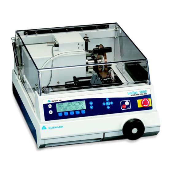
IsoMet 5000 Linear Precision Saw The IsoMet 5000 is an easy to use automatic linear saw that includes the SMARTCUT system to automatically adjust the feed rate to provide consistent, quality cuts and to prevent specimen and machine damage. A 2m Specimen Positioning System allows for precise applications and enables the cutting of delicate specimens without deformation. -
Page 8: Safety Information
F / 5° C to 40° C) and non-condensing humidity ranges (30-90%). Machine Use and Care All operators should be trained in the use of the IsoMet 5000. If training is needed contact Buehler at 800.BUEHLER (800.283.4537) or your local Buehler Sales Representative. -
Page 9: Safety Terms
NOTICE indicates practices not related to personal injury. Unpacking The IsoMet 5000 Linear Precision Saw is shipped fully assembled and has been carefully packaged to protect it during transit from the factory to your location. Carefully unpack and check contents. If any components are missing or damaged, save the packing list and materials and advise the carrier and Buehler of the discrepancy. -
Page 10: Installation
Lift the IsoMet 5000 Linear Precision Saw out of the carton and position it on a table so it overhangs the edge. Remove all bolts securing the IsoMet 5000 Linear Precision Saw to the wood base. -
Page 11: Blade Installation
Blade Installation Flanges support the wafering and abrasive blades. Failure to provide adequate flange support may result in curved cuts and damaged blades. When cutting always select the maximum flange diameter in proportion with the size of the specimen. (For more details see Accessories and Supplies.) Installing a Blade 1. -
Page 12: Cooling And Lubrication
During high frequencies of use or when using abrasive cut-off wheels with the IsoMet 5000 Linear Precision Saw, the coolant tank should be cleaned regularly. The drain screen should be cleaned between each cut to prevent blockage. -
Page 13: External Recirculating System
External Recirculating System WARNING Personal Injury. Disconnect the power supply before performing any maintenance or adjustments. 1. Find a suitable location for the External Recirculating System. 2. Set the tank on a four-wheeled recirculating cart (P/N 16-1497). 3. Slide the 1-inch drain hose over the drain outlet pipe and secure the drain hose with the supplied hose clamp (see Figure 2) 4. -
Page 14: Isomet 5000 Controls And Functions
When raised, the counter-balanced hood will remain in the open position, activating a safety-lock switch disabling the controls for the cutting motor. 1. Activate power to the IsoMet 5000. Flip the power switch on the back of the machine to the ON position. - Page 15 Once a position is determined, press the ZERO button and the DISTANCE REMAINING value will change to .00, indicating the SOFT HOME position. Increase The Increase button will incrementally increase (raise) a parameter’s value. The maximum values for the IsoMet 5000 are: BLADE SPEED = 5000 rpm ...
-
Page 16: Directional Buttons
EMERGENCY STOP Is the big red knob on the right side of the front panel. When pressed all electrical power is disconnected from the blade and all moving parts, disabling any further operations. A warning message will appear when the Emergency Stop button is pushed. To return power, turn the Emergency Stop knob clockwise. -
Page 17: Isomet 5000 Display Screens And Commands
IsoMet 5000 Display Screens and Commands Parameter Fields There are seven (7) different parameter fields available. Use the SCROLL button to scroll though the LCD Screens to display and highlight the parameters. BLADE FEED DISTANCE Parameter fields are highlighted using the... -
Page 18: L1 Display Screen
L1 Display Screen BLADE FEED DISTANCE SPEED RATE REMAINING 4250rpm .64in/min 1.00in CUTTING BLADE PUMP FEED CYCLE MOTOR MOTOR MOTOR L1 Display Screen Commands Button [1] CUTTING CYCLE starts, stops, and pauses the cutting cycle. Button [2] BLADE MOTOR toggles the blade motor ON and OFF. The blade will rotate at a set speed and the hood must be closed. -
Page 19: L2 Display Screen
L2 Display Screen BLADE FEED DISTANCE SPEED RATE REMAINING 4250rpm .64in/min 1.00in CUTTING ROTATING SOFT SOFT CYCLE CHUCK START STOP L2 Display Screen Commands Button [1] CUTTING CYCLE starts, stops, and pauses the cutting cycle. Button [2] ROTATING CHUCK toggles the rotating chuck ON and OFF. The chuck will rotate at a constant speed. -
Page 20: L3 Display Screen
L3 Display Screen BLADE FEED DISTANCE SPEED RATE REMAINING 4250rpm .64in/min 1.00in CUTTING DRESS SELECT IMPERIAL CYCLE BLADE ENGLISH UNITS LANGUAGE L3 Display Screen Commands Button [1] CUTTING CYCLE starts, stops, and pauses the cutting cycle. Button [2] DRESS BLADE sets the correct blade-dressing parameters and activates the automatic dressing mechanism (if attached). -
Page 21: L4 Display Screen
MEMORY LOAD will change the LCD Screen to add or “load” a method to the Button [1] IsoMet 5000. (See Loading a Method on page 32 for more details.) Button [2] MEMORY SAVE will save a method to the IsoMet 5000. -
Page 22: Specimen Positioning
The Hard Home position is when the turret is all the way at the back of the saw and the precision positioning device is fully retracted into its housing. Hard Home must be done: The first time the IsoMet 5000 is powered on. Every time the precision positioning is removed and reinstalled. ... -
Page 23: Positioning A Specimen With An Unknown Thickness (Without The Specimen Positioning System Installed)
Positioning a Specimen with an Unknown Thickness (without the Specimen Positioning System Installed) 1. Turn the hand crank clockwise until the blade is beyond the chuck position. 2. Determine the cut length of the specimen. a. Position the specimen in the chuck so the cutting blade can pass by the chuck without touching the specimen (see Figure 5). - Page 24 4. Turn the crank clockwise to position the blade behind the specimen. The value under REMAINING DISTANCE does not have to equal .00 in (or .00 mm) after repositioning the blade. 5. Reposition the specimen and tighten the vise to prevent the specimen from moving. Figure 5 Positioning the specimen Figure 6 Blade behind the specimen Figure 7 Blade almost touching the specimen...
-
Page 25: Positioning A Specimen With A Known Thickness (Without The Specimen Positioning System Installed)19
Positioning a Specimen with a Known Thickness (without the Specimen Positioning System Installed) 1. Position the specimen in the chuck. 2. Turn the hand crank clockwise until the blade is beyond the chuck position (see Figure 9). 3. Turn the hand crank counter-clockwise to bring the blade forward until it is just behind the and almost touching the specimen (see Figure 10). -
Page 26: Positioning A Specimen With The Specimen Positioning System Installed
Positioning a Specimen with the Specimen Positioning System Installed 1. Turn the hand crank clockwise until the blade is beyond the chuck position 2. Determine the cut length of the specimen. a. Position the specimen in the chuck so the cutting blade can pass by the chuck without touching the specimen (see Figure 9). -
Page 27: Operation
WARNING Equipment Damage. The IsoMet 5000 Linear Precision Saw is designed to only operate with the cover closed. This prevents manual feeding of specimen materials or dressing sticks into the rotating blade, which could result in personal injury and/or blade damage. -
Page 28: Single Cut With The Specimen Positioning System With The Datum Off Function
Single Cut with the Specimen Positioning System with the DATUM OFF Function When the DATUM function is in the OFF position, the SPECIMEN QUANTITY equals the total number of cuts. 1. Adjust the BLADE SPEED, FEED RATE, CUTTING LENGTH, SAMPLE THICKNESS, and BLADE THICKNESS. -
Page 29: Single Cut With The Specimen Positioning System With The Datum On Function
Single Cut with the Specimen Positioning System with the DATUM ON Function When the DATUM function is in the ON position, the SPECIMEN QUANTITY equals the number of cuts plus one (1). The first cut is used to get a “clean” cut surface on the specimen and is then discarded. 1. -
Page 30: Multiple Cuts Using The Specimen Positioning System With The Datum Off Function
Multiple Cuts Using the Specimen Positioning System with the DATUM OFF Function When the DATUM function is in the OFF position, the SPECIMEN QUANTITY equals the total number of cuts. 1. Adjust the BLADE SPEED, FEED RATE, CUTTING LENGTH, SAMPLE THICKNESS, SPECIMEN QUANTITY, and BLADE THICKNESS. -
Page 31: Multiple Cuts Using The Specimen Positioning System With The Datum On Function
Multiple Cuts Using the Specimen Positioning System with the DATUM ON Function When the DATUM function is in the ON position, the SPECIMEN QUANTITY equals the number of cuts plus one (1). The first cut is used to get a “clean” cut surface on the specimen and is then discarded. 1. -
Page 32: Manual Cutting
NOTICE Too large of a specimen may cause the flange to advance into the specimen causing damage to both the flange and specimen. If you need to cut large specimens, reposition the specimen using a different mount. During operation observe the saw’s performance. Due to differences in specimen thickness and density/consistency, the FEED RATE parameter can be adjusted for optimum cutting conditions. -
Page 33: Smart Cut: Checking And Adjusting The Feed Rate
SMART CUT: Checking and Adjusting the Feed Rate During the CUTTING CYCLE, the IsoMet 5000 will monitor the load that is applied to the blade. If an overload condition occurs, the IsoMet will automatically decrease the FEED RATE to maintain an optimum cutting condition. -
Page 34: Dressing The Blade
If a 3-inch blade is used, slide the T-mount so the left-end of the dressing stick does not hit the spindle base. If the Automatic Dressing System is not attached, insert a dressing stick in a specimen holder. Place the specimen holder in the path of the blade and clamp it securely. -
Page 35: Automatic Blade Dressing, Rotating Chuck, And Specimen Positioning System
Automatic Blade Dressing, Rotating Chuck, and Specimen Positioning System The IsoMet 5000 is shipped with the Specimen Positioning System and Automatic Dressing System already attached. The following instructions are for replacing the Automatic Dressing System, the Specimen Positioning System, and a Rotating Chuck. -
Page 36: Installing The Specimen Position System
2. Clean the mounting embossment if the X T-slot bed is not installed. 3. Attach the T-slot table to the IsoMet 5000 (there will be four (4) screws). 4. Align the T-nut and posts on the bottom of the Specimen Positioning System to the T-slot and slide into position. -
Page 37: Removing The Automatic Blade Dressing System (Catalog Number 11-2696)
Removing the Automatic Blade Dressing System (Catalog Number 11-2696) 1. Turn OFF the IsoMet 5000. 2. Disconnect the power cable from the control housing. 3. Remove and keep the two (2) mounting screws. 4. Recap the bottom power socket. Installing the Automatic Blade Dressing System 1. -
Page 38: Loading And Saving Methods
Loading and Saving Methods The IsoMet 5000 has two types of methods a user can select from: B# Methods: (Buehler Methods) are thirty-five (35) Buehler established and proven methods that cannot be altered by the user. U# Methods: (User Methods) are twenty (20) methods that can be created and saved by the user. -
Page 39: To Save A Method
To Save a Method Press the Scroll button until the L4 Screen appears. The screen will change to display MEMORY LOAD, MEMORY SAVE, and DATUM OFF (or ON). BLADE FEED DISTANCE SPEED RATE REMAINING 4250rpm .64in/min 1.00in MEMORY MEMORY DATUM LOAD SAVE 1. -
Page 40: Warning Messages
Indicates the Emergency Stop button has been pressed. 1. Examine the machine for problems. 2. Rotate the Emergency Stop button counter-clock wise until it pops out. The IsoMet 5000 will be in the PAUSE mode. 3. Press the CUTTING CYCLE button to continue operation. -
Page 41: Maintenance
Maintenance The IsoMet 5000 Linear Precision Saw will continue to perform at optimum levels with proper care, daily cleaning, and general maintenance. The protective hood and touch-panel control pad should be cleaned using mild soap and water applied ® with a soft cloth. Do not use ammonia-based cleaners, i.e. Windex . -
Page 42: Automatic Blade Dressing
Periodically this fine-toothed shaft will need to be clean. Cleaning the Automatic Blade Dressing shaft 1. Turn off the IsoMet 5000. 2. Open the hood. 3. Pull the T-mount out of the housing. -
Page 43: Trouble Shooting Chart
Trouble Shooting Chart Problem Possible Cause Correction Check the power cord The unit is not plugged in connection The IsoMet does not power on Check the rear power switch The unit is not powered on Fill the fluid to the correct level Fluid level may be too low Remove screen and clean Tank screen may need cleaning... - Page 44 ® IsoMet 5000 Drawings Note: Drawings and Parts List are subject to change without notice. Figure 14 Control Housing Sub-Assembly Diagram (2780S803) MA112780_38.6 [Original Instructions] 9/19/2011...
- Page 45 ® IsoMet 5000 Drawings Note: Drawings and Parts List are subject to change without notice. Figure 15 Hood Sub-Assembly Diagram (2680S802) MA112780_38.6 [Original Instructions] 9/19/2011...
- Page 46 ® IsoMet 5000 Drawings Note: Drawings and Parts List are subject to change without notice. Figure 16 Turret Sub-Assembly Diagram (2780S800) MA112780_38.6 [Original Instructions] 9/19/2011...
- Page 47 ® IsoMet 5000 Drawings Note: Drawings and Parts List are subject to change without notice. Figure 17 Spindle Sub-Assembly Diagram (2680S806) MA112780_38.6 [Original Instructions] 9/19/2011...
- Page 48 ® IsoMet 5000 Drawings Note: Drawings and Parts List are subject to change without notice. Figure 18 Turret Core Sub-Assembly Diagram (2780S805) MA112780_38.6 [Original Instructions] 9/19/2011...
- Page 49 ® IsoMet 5000 Drawings Note: Drawings and Parts List are subject to change without notice. Figure 19A Feed Screw Sub-Assembly Diagram (2780S801) Part 1 MA112780_38.6 [Original Instructions] 9/19/2011...
- Page 50 ® IsoMet 5000 Drawings Note: Drawings and Parts List are subject to change without notice. Figure 19B Feed Screw Sub-Assembly Diagram (2780S801) Part 2 MA112780_38.6 [Original Instructions] 9/19/2011...
- Page 51 ® IsoMet 5000 Drawings Note: Drawings and Parts List are subject to change without notice. Figure 20 Pump Assembly Exploded Diagram (2780S804) MA112780_38.6 [Original Instructions] 9/19/2011...
- Page 52 ® IsoMet 5000 Drawings Note: Drawings and Parts List are subject to change without notice. Figure 21 IsoMet 5000 Top View of Assembly Diagram (2780900B) MA112780_38.6 [Original Instructions] 9/19/2011...
- Page 53 ® IsoMet 5000 Drawings Note: Drawings and Parts List are subject to change without notice. Figure 22 Bottom View of IsoMet 5000 Assembly Diagram (2780900C) MA112780_38.6 [Original Instructions] 9/19/2011...
- Page 54 ® IsoMet 5000 Drawings Note: Drawings and Parts List are subject to change without notice. Figure 23 IsoMet 5000 Electrical Diagram (2780900E) MA112780_38.6 [Original Instructions] 9/19/2011...
- Page 55 ® IsoMet 5000 Drawings Note: Drawings and Parts List are subject to change without notice. Figure 24 IsoMet 5000 Packaging Diagram (2780900D) MA112780_38.6 [Original Instructions] 9/19/2011...
- Page 56 IsoMet 5000 Parts List Part Number Description Note: Drawings and Parts List are subject to change without notice. MA112780 MANUAL, INSTR ISOMET 5000 R0539B TERMINAL #6 RING 16-14 NIT R10275 SCREW, M4 X 16 SOC HD SS R10310 SCREW, 5/16-18 X 1-3/4 HEX HD...
- Page 57 ® IsoMet 5000 Parts List Part Number Description Note: Drawings and Parts List are subject to change without notice. 112686 IRREGULAR SPECIMEN CHUCK S. IS112682 INSTRUCTIONS 112682_83_84_85_86 L112686 LABEL FOR 112686 R8095 LABEL, A SIZE R0965 SCREW, 10-32 X 3/4 SOC SS R6106 CARTON, 4X3X3 200# OYS WHT R6316...
- Page 58 MACHINED DRESSING 2680S376 CASTING DRESSING 2680S520 CABLE, BLADE DRESSING 821545 WASHER, M8.4ID 114267 ISOCUT WAFERING BLADE 7X.02 2780S911 ISOMET 5000 UNIT ASSEMBLY AK#207 ACCESSORY KIT F/112680/1127 LAK#207 LABEL FOR AK#207 R8095 LABEL, A SIZE MA114207 SHEET,INSTRUCTION-7"C/O WHE R6743 CARTON, BOOKFOLD...
- Page 59 ® IsoMet 5000 Parts List Part Number Description Note: Drawings and Parts List are subject to change without notice. 112750 2 UM SAMPLE POS. SYS ISOMET IS112750 INSTRUCTIONS 2UM SAMPLE POS. SYST R10172 BALL, SS 3/8-C55 R10202 SCREW, SET M6 X 35 SS R10209 SCREW, SET M3 X 6 STEEL R10214...
- Page 60 ® IsoMet 5000 Parts List Part Number Description Note: Drawings and Parts List are subject to change without notice. 2680S392 U-PIPE FOR ISOMET 4000/5000 2680S394 HOSE CLAMP, ISOMET 4000/500 R10892 CLAMP, 40-60MM HOSE 2680S802 HOOD SUB-ASSEMBLY R0612W WASHER, #10 FLAT SS R0615W WASHER, 1/4IN SS R0617W...
- Page 61 R10892 CLAMP, 40-60MM HOSE 2780S074 X-TABLE ASSEMBLY ISOMET 500 2780S508 CABLE,30PIN LOGIC TO MTR CN 2780S807 ISOMET 5000 PRE-ASSEMBLY R0542A TERMINAL 1/4 RING 16-14 FIG R0603W WASHER, .125 X .312 X 04 FLAT R0612LWE WASHER, #10 EXTERNAL LOCK SS R0969...
- Page 62 ® IsoMet 5000 Parts List Part Number Description Note: Drawings and Parts List are subject to change without notice. R7760 TUBING-HEAT SHRINK .25 DIA R7845 SCREW, 6-32 X 3/16 PN PHIL HD R8025 TUBING-HEAT SHRINK .19 DIA R8078 SCREW, 10-32 X 7/8 PAN PHIL S R8370 CABLE TIE, MOUNT R8814...
- Page 63 RING, BN-12 X 10-S TOLERANC R4559 ADHESIVE-ANAEROBIC THREAD G 0.01 R6640 CARTON,6X3X3 200# OYS WHT R7606 ADHESIVE HIGH TEMP 0.01 2680S025 PULLEY, SPINDLE MICRO-V 2680S380 SHAFT, SPINDLE ISOMET 5000 2680S381 HOUSING, SPINDLE 821523 WASHER, M5 SS MA112780_38.6 [Original Instructions] 9/19/2011...
- Page 64 ® IsoMet 5000 Parts List Part Number Description Note: Drawings and Parts List are subject to change without notice. 821543 WASHER, M5 LARGE OD STNL STEE 2780S035 SPINDLE, SCREW 2780S805 CORE, TURRET SUB-ASSEMBLY B704005 SCREW, M3 X 6 REC PAN HD SS R0609LW WASHER, SPLK #8 STN STL R10007...
- Page 65 2680S073 HOUSING, CONTROL PANEL 2680S048 HOUSING, CONTROL PANEL CAST 2680S521 CABLE, BLADE DRESSING INHOU 2780S505 NAMEPLATE, ISOMET 5000 NEW 2780S509 CABLE, X1 LOGIC TO HOOD SWI 2780S512 CABLE, LOGIC PCB TO X-TBL P 2780S516 HARNESS, PCB TO X-TBL CONNE 2780S526 LCD &...
- Page 66 ® IsoMet 5000 Accessory Drawings Note: Drawings and Parts List are subject to change without notice. Figure 25 Automatic Dressing System Diagram MA112780_38.6 [Original Instructions] 9/19/2011...
- Page 67 ® IsoMet 5000 Accessory Drawings Note: Drawings and Parts List are subject to change without notice. Figure 26 Automatic Dressing System Diagram – Detail A MA112780_38.6 [Original Instructions] 9/19/2011...
- Page 68 ® IsoMet 5000 Accessory Drawings Note: Drawings and Parts List are subject to change without notice. Figure 27 Specimen Positioning System Assembly Diagram MA112780_38.6 [Original Instructions] 9/19/2011...
- Page 69 ® IsoMet 5000 Accessory Drawings Note: Drawings and Parts List are subject to change without notice. Figure 28 X-Table Assembly Diagram (11-2750) Part A MA112780_38.6 [Original Instructions] 9/19/2011...
- Page 70 ® IsoMet 5000 Accessory Drawings Note: Drawings and Parts List are subject to change without notice. Figure 29 X-Table Assembly Diagram (11-2750) Part B MA112780_38.6 [Original Instructions] 9/19/2011...
- Page 71 ® IsoMet 5000 Accessory Drawings Note: Drawings and Parts List are subject to change without notice. Figure 30 Specimen Positioning System Diagram MA112780_38.6 [Original Instructions] 9/19/2011...
- Page 72 ® IsoMet 5000 Accessory Drawings Note: Drawings and Parts List are subject to change without notice. Figure 31 Precision Table Sub-Assembly Diagram (2780901B) MA112780_38.6 [Original Instructions] 9/19/2011...
-
Page 73: Isomet 5000 Precision Saw Application Guide
IsoMet 5000 Precision Saw Application Guide IsoMet 5000 Precision Saw Application Guide (0.5" (13 mm) diameter rod example specimen) Estimated Buehler Feed Rate Diamond Speed Cutting Method Specimen Material Blade Type in./min Concentration (rpm) Time Number mm/min (min:sec) 8µm graphite fiber reinforced... - Page 74 IsoMet 5000 Precision Saw Application Guide Buehler Estimated Feed Rate method Diamond Speed Cutting Specimen Material Blade Type in./min number Concentration (rpm) Time mm/min (min:sec) Brass 11-4217 Abrasive wheel ------ 4000 1:15 0.40" (10 mm) Gray cast iron Series 15 HC diamond...
- Page 75 Buehler, Asia-Pacific Web Site: http://www.buehler-asia.com 69570 Dardilly, France Fax: (852) 2307 0223 Tel: (04) 37 59 81 20 E-mail: info@buehler.com.hk Fax: (04) 37 59 81 29 Email: sav@buehler.fr For all other service inquiries contact Buehler at www.buehler.com/locations/service.htm. MA112780_38.6 [Original Instructions] 9/19/2011...
- Page 76 Notes MA112780_38.6 [Original Instructions] 9/19/2011...
Need help?
Do you have a question about the IsoMet 5000 and is the answer not in the manual?
Questions and answers