Table of Contents
Advertisement
Advertisement
Table of Contents

Summary of Contents for Ironton 61531
- Page 1 8 ½ Inch Drywall Sander Owner’s Manual WARNING: Read carefully and understand all ASSEMBLY AND OPERATION INSTRUCTIONS before operating. Failure to follow the safety rules and other basic safety precautions may result in serious personal injury. Item #61531 READ & SAVE THESE INSTRUCTIONS...
- Page 2 Thank you very much for choosing an Ironton™ product! For future reference, please complete the owner’s record below: Serial Number/Lot Date Code: ________________________________ Purchase Date: ____________________________________________ Save the receipt, warranty, and this manual. It is important that you read the entire manual to become familiar with this product before you begin using it.
-
Page 3: Table Of Contents
Table of Contents Intended Use ............................4 Technical Specifications ........................4 Important Safety Information ....................... 4 Specific Operation Warnings ....................... 6 Grounding .............................. 6 Extension Cords ............................ 7 Main Parts of Drywall Sander ......................8 Assembly Instructions .......................... 9 Before Each Use ............................ 9 Operating Instructions .......................... -
Page 4: Intended Use
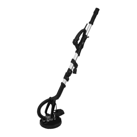
Intended Use The Ironton 8 ½ Inch Drywall Sander is designed to sand drywall or plaster walls and ceilings in any position. The sander provides a superior finish and is faster than conventional methods for both new construction and renovation work. Use the built-in extensions to change the length of the tool from 4ft. - Page 5 Do not use the sander where there is a risk of causing a fire or an explosion; e.g., in the presence of flammable liquids, gases, or dust. The product can create sparks, which may ignite the flammable liquids, gases, or dust. ...
-
Page 6: Specific Operation Warnings
Disconnect the power/air supply from the product and place the switch in the locked or off position before making any adjustments, changing accessories, or storing the tool. Such preventive safety measures reduce the risk of starting the tool accidentally. ... -
Page 7: Extension Cords
The grounding prong in the plug is connected through the green wire inside the cord to the grounding system in the tool. The green wire in the cord must be the only wire connected to the tool’s grounding system and must never be attached to an electrically live terminal. Your tool must be plugged into an appropriate outlet, properly installed and grounded in accordance with all codes and ordinances. -
Page 8: Main Parts Of Drywall Sander
18 AWG 16 AWG 16 AWG 14 AWG 6-10 18 AWG 16 AWG 14 AWG 12 AWG 10-12 16 AWG 16 AWG 14 AWG 12 AWG 12-16 14 AWG 12 AWG NOT RECOMMENDED When using more than one extension cord to make up the total length, make sure each cord contains at least the minimum wire size required. -
Page 9: Assembly Instructions
Assembly Instructions Installing the Sander Tighten the folded button and connect the body with the front handle. Loosen the back handle adjustment knob. Connect the back handle and the assisting handle. Adjust the length of the handle and tighten the adjustment knob. See the following page for images. Before Each Use ⚠WARNING ... - Page 10 tool may contact hidden wiring or its own cord. Never place your hand near the rotating accessory. Accessories may kickback over your hand. Do not point the tool at people or animals. Hold the handle firmly. Do not place your hands over the rotating disc and stand still while using the sander.
-
Page 11: After Each Use
Replacing Sandpaper Completely remove the old sandpaper from the disc. Make sure all of it is removed. Lay the new sandpaper in the correct position, making sure the hole in the sandpaper matches the hole in the sanding pad. Replacing the Sanding Pad Before removing the old sandpaper, use the hex key to loosen the screw in the center of the sanding pad. -
Page 12: Troubleshooting
Troubleshooting Use the table below to troubleshoot problems before contacting service personnel or your local dealer. If the problem continues after troubleshooting, call your local dealer for assistance. Failure Possible Cause Corrective Action Power is not connected. Connect the power. Sander will not start. -
Page 13: Parts Diagram (1 Of 2)
Parts Diagram (1 of 2) Page 13 of 19... - Page 14 Page 14 of 19...
-
Page 15: Parts List
Parts List Reference Part Description Quantity Left back handle Right back handle Connecting pin Alu. inner tube Left middle handle Right middle handle Quick release screw Quick release locking nut Switch Speed controller Power line Sander sheath Alu. Tube seal cover Alu. - Page 16 Reference Part Description Quantity Brush carrier cover Housing side cover Bearing 606 Bearing snap ring 10 Large helical gear Bearing 6000 Gear box cover Oil seal Output shaft Square key 3*10 Spring Plastic disc Plastic disc cover Screw 3*1 Big circle brush Tray Shim 6 M6*20...
-
Page 17: Replacement Parts
Replacement Parts For replacement parts and technical questions, please call Customer Service at 1-800-222-5381. Not all product components are available for replacement. The illustrations provided are a convenient reference to the location and position of parts in the assembly sequence. ... -
Page 18: Limited Warranty
Northern Tool and Equipment Company, Inc. ("We'' or ''Us'') warrants to the original purchaser only (''You'' or ''Your'') that the Ironton product purchased will be free from material defects in both materials and workmanship, normal wear and tear excepted, for a period of one year from date of purchase. - Page 19 Distributed by: Northern Tool & Equipment Company, Inc. Burnsville, Minnesota 55306 www.northerntool.com Made in China Page 19 of 19...

Need help?
Do you have a question about the 61531 and is the answer not in the manual?
Questions and answers