Table of Contents
Advertisement
Radiolink Mini Pix
(setup for multicopter)
User Manual
Technical updates and additional programming examples available at: http://www. radiolink.com
This manual is based on the ARDUPILOT, add some introductions about how to setup with
transmitter AT9S, more details about how to use flight controller PIXHAWK-series can from this
website:
http://ardupilot.org/copter/docs/initial-setup.html
Please start here for getting service if you have any questions during using the MINI PIX.
www.radiolink.com
Phone: +86-755-88361717-882
Email:
after_service@radiolink.com.cn/after_service1@radiolink.com.cn
1
Advertisement
Table of Contents

Related Manuals for RadioLink Mini Pix


Summary of Contents for RadioLink Mini Pix
- Page 1 This manual is based on the ARDUPILOT, add some introductions about how to setup with transmitter AT9S, more details about how to use flight controller PIXHAWK-series can from this website: http://ardupilot.org/copter/docs/initial-setup.html Please start here for getting service if you have any questions during using the MINI PIX. www.radiolink.com Phone: +86-755-88361717-882 Email:...
-
Page 2: Table Of Contents
4.1 Radio FailSafe setup ..........................39 4.2 EKF FailSafe( Firmware MPV3.2.1+) ....................... 44 5. Optional Hardware Setup ..........................45 5.1 Install Mini Pix on Drone ......................... 45 5.2 Connect the Spare Parts .......................... 48 5.3 Arming and Disarming………………………………………………………………………………………………………………………..51 5.4 ESC Calibration(first flight) ........................55 5.5 Calibrate Level ............................ -
Page 3: Mini Pix Introduction
Shell completely closed to protect, prevent the interaction effects of air current wake on air pressure when flight. The main board has air pressure vent to ensure the accuracy of the barometer testing. Shell design and vibration damping by software make Radiolink mini PIX achieved better Altitude Hold effect. -
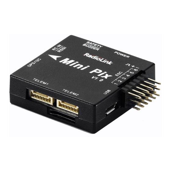
Page 4: Connectors And Parameters
1.2 Connectors... - Page 5 Parameters...
-
Page 6: Warning
Please don't fly in the rain! For the users who is the first time to use mini PIX, we suggest that you use it follow these steps: 1. You have to install the mission planner and driver from here and familiar with the menu. - Page 7 It will hit you download Net Framework 4.6.2 automatically when you click this website. Then you need download Mission Planner, you can download from our website: www.radiolink.com Open the Microsoft installer file and select Run to run the installation utility.
-
Page 8: Misson Planner Introduction
HELP: you can get help when you have questions about MP 3. Initial Setup First, you have to upgrade the firmware you need when you the first time ready to use MINI PIX. Radiolink Mini Pix is default with quadcopter firmware, you have to install the right firmware if you use the other frame drone. - Page 9 Click “Yes” to install the firmware, Disconnect the USB cable, click OK and then reconnect USB cable immediately (Pay attention: Mini Pix will have failed to connect if there are more than one COM, please remove other equipment if disconnect).
- Page 10 After upgrade firmware 3.1 or after version 3.1, it will pops up a warning box that shows motors will run at idle speed after disarmed. Please click “CONNECT” to connect your Mini Pix and computer when firmware has installed successful.
-
Page 11: Frame Type
(1) It takes a long time to read the parameters. (2) There are not have “Load custom firmware” and “Pick previous firmware”. (3) INITIAL SETUP menu missed some parameters. 3.2 Frame Type Please setup as below:... -
Page 12: Accelerometer Calibration
2. Mandatory Hardware->Frame Type 3. Choose Quad or Hexa or other frame types as you need 3.3 Accelerometer Calibration Make sure the Mini Pix is keeping horizontal when do the accel calibration. 1. Place vehicle level and press any key to save setting. - Page 13 2. Place vehicle on its LEFT side and press any key to save setting. 3. Place vehicle on its RIGHT side and press any key to save setting.
- Page 14 4. Place vehicle DOWN and press any key to save setting.
- Page 15 5. Place vehicle UP and press any key to save setting. 6. Place vehicle on its BACK and press any key to save setting.
-
Page 16: Compass Calibration
If the GPS mounted with the same direction with flight controller, then it need not to setup the direction of GPS in MP but if you mounted the GPS with the different direction of MINI PIX, you have to setup in the MP. - Page 17 Keep the same direction with flight controller. positioning. Please fixed Mini Pix and TS100, then click “Start” and turn Mini Pix and TS100 till the progress bar of Mag 1 and 2 to the end and comes out the MAG_CAL_SUCCESS marked words.
- Page 18 Calibrate the compass as these steps below: Hold the vehicle in the air and rotate it slowly so that each side (front, back, left, right, top and bottom) points down towards the earth for a few seconds in turn.
- Page 19 The mission planner will remind you when the compass has calibrated success. Click OK and then reconnect MINI PIX to computer, compass calibrate success after restart the MINI PIX.
-
Page 20: Radio Calibration
3.5 Radio Calibration Mission Planner This article shows how to perform radio control calibration using RC transmitters are used to control vehicle movement and orientation. Copter and Plane minimally control throttle, pitch, roll and yaw, while on Rover we just control throttle and roll. Each of these control signals are mapped to transmitter stick/switch(s) and in turn to autopilot channels from the connected receiver. - Page 21 For safety, you should disconnect the battery and/or remove propellers before preforming radio calibration.
- Page 22 Bind your transmitter and receiver before calibrate radio, connect MINI PIX to computer via USB cable and then turn on transmitter. The RC receiver ask to connect to the RC port of MINI PIX. The transmitter will make AT9S as an example in this manual.
- Page 23 3. Click the CONNECT 4. Choose INITAIL SETUP—Mandatory Hardware—Radio Calibration 5. Click “Calibrate Radio” There are two tool tips after you click “OK”, one for make sure both your transmitter and receiver are powered on and connected, and the motor of your drone does not have power and without propellers.
- Page 24 R9DS means work as SBUS signal). You can check if every corresponding red bar for every channel is work as below: CH1: low position = roll (towards the left), up position= roll (towards the right). CH2: low position =pitch(forward), up position =pitch(backwards). CH3: low position =reduced speed, up position =speed up.
-
Page 25: Flight Modes
You can setup six flight modes once and max setup eight modes combine with AUX-CH (CH7 and CH8). Flight modes setting steps: 1. Connect MINI PIX and receiver (connect the RC port of MINI PIX, and make sure receiver work as SBUS signal). 2. Make sure transmitter bind to receiver success. - Page 26 In flight modes menu, it’s very clear that the flight modes, the PWM numerical interval of six flight modes you have set and choose Simple Mode/Super Simple Mode or not. Most of the RC fans setup the Flight Mode 1 is Stabilize, the other five flight mode will be setup according to users’...
-
Page 27: Stabilize Mode
3.Setup Flight Mode 1 is Stabilize both in Mission Planner and transmitter. Make sure the -swt- is ON (by press the 3 Posi-SW or 2 Posi-SW to make it ON or OFF) and then you can setup the PWM data. Setup the PWM value according to the default numerical interval (change the value by turn the dial, press the Push button when you choose the right value. -
Page 28: Acro Mode(Fpv)
(5) The throttle sent to the motors is automatically adjusted based on the tilt angle of the vehicle (i.e. increased as the vehicle tilts over more) to reduce the compensation the pilot must do as the vehicle’s attitude changes. Always switch into a manual mode such as stabilize if the autopilot fails to control the vehicle. Maintaining control of your copter is your responsibility. -
Page 29: Altitude Hold Mode
Parameters Setting ACRO_RP_P controls the rotation rate for the roll and pitch axis. The default, 4.5, will command a 200deg/sec rotation rate. Higher values lead to higher rotation rates, lower to slower rotation rates. ACRO_YAW_P controls the rotation rate for the yaw axis. The default, 4.5, like roll and pitch, will command a 200deg/sec rotation rate. -
Page 30: Auto Mode
Note: The flight controller uses a barometer which measures air pressure as the primary means for determining altitude (“Pressure Altitude”) and if the air pressure is changing in your flight area due to extreme weather, the copter will follow the air pressure change rather than actual altitude. When fitted and enabled, a downward facing rangefinder such as LiDAR or SONAR will automatically provide even more accurate altitude maintenance, up to the limit of the sensor. - Page 31 AUTO should be set-up as one of the Flight Modes on the flight mode switch. Make sure that the GPS is positioning first: The LED of Mini Pix is green. ▪ The LED of GPS and compass module is blinking.
-
Page 32: Poshold Mode
the flight mode switch is moved to Auto. If the first command in the mission is a take-off command but the vehicle is already above the take-off command’s altitude the take-off command will be considered completed and the vehicle will move onto the next waypoint. At any time, the pilot can retake control from the autopilot by returning the flight mode switch to another flight mode such as Stabilize or Loiter. -
Page 33: Rtl Mode
The HDOP value can be made clearly visible through the mission planner’s Quick screen by double clicking and then selecting “gpshdop” from the large grid of checkboxes. The maximum brake-angle can be set with the PHLD_BRAKE_ANGLE parameter (i.e. 3000 = the vehicle will lean back up to 30degrees). - Page 34 this mode. Before arming, ensure that the APM’s blue LED is solid and not blinking. For a GPS without compass, the LED will be solid blue when GPS lock is acquired. For the GPS+Compass module, the LED will be blinking blue when GPS is locked. RTL will command the copter to return to the home position, meaning that it will return to the location where it was armed.
-
Page 35: Simple And Super Simple Modes
Notes 1. Other navigation settings also have an influence over RTL mode: (1) WPNAV_ACCEL (2) WPNAV_SPEED_DN (3) WPNAV_SPEED_UP 2. To use RTL, GPS lock needs to be achieved (Blue GPS LED and Blue APM LED on solid not blinking) before arming and takeoff to establish the home or launch position. 3. - Page 36 Without Simple or Super Simple enabled, the pilot’s transmitter stick inputs are applied in the orientation of the copter. For example, in the diagram above when the pilot applies roll input right (red) the vehicle rolls to its right. With the copter is facing in the same direction as the pilot, it is relatively easy to control the vehicle but when the vehicle is facing towards the pilot an inexperienced pilot will feel that the controls are all reversed.
- Page 37 Similar to the “care free” mode on other systems, this mode allows you to fly your copter as though it were pointed in the direction it was pointed when it was armed regardless of its current heading orientation. So, if you hold the pitch stick forward the copter will fly away from you, pull the pitch stick back and it will come back towards home.
-
Page 38: More Flight Mode
If the pilot holds full right roll the vehicle will fly a circle clockwise around the pilot (although the circle’s radius may tend to grow slightly with each orbit due to “lag”). The disadvantage is that mode require a GPS lock because so you should ensure you have GPS lock before take-off. -
Page 39: Failsafe Setting
4. F/S(failsafe) Setting 4.1 Radio Failsafe Setup Mini Pix supports Return-To-Launch in cases where contact between the Pilot’s RC transmitter and the flight controller’s receiver is lost. This page explains this failsafe’s setup and testing. Note the “Radio failsafe” was previously called “Throttle failsafe” because of the way in which some receivers use the throttle channel to signal the loss of contact. - Page 40 Receiver and flight controller MINI PIX setup: By default, a newly purchased receiver will be set-up to simply hold all channels at their last known position when the receiver and transmitter lose contact. This is not good because the flight controller has no way to know that the Pilot has lost control of the vehicle.
- Page 41 if it takes the vehicle outside of RC range (not recommended). In all other cases the vehicle will RTL. (3) “Enable always LAND” to force the vehicle to Land immediately if it loses RC contact. Set the “FS PWM” value to be: (1) at least 10 PWM higher than your Channel 3’s PWM value when the throttle stick is fully down and the transmitter is off.
- Page 42 You can turn off transmitter to check if the Failsafe function setup success(the PWM of CH3 is smaller than 975) If enabled and set-up correctly the radio Failsafe will trigger if: (1) The pilot turns off the RC transmitter. (2) The vehicle travels outside of RC range. (3) The receiver loses power (unlikely).
- Page 43 Copter also supports Battery, Ground Station and EKF/DCM failsafes. You can check your Failsafe by performing the following tests with the MINI PIX connected to the Mission Planner either via a USB cable or telemetry link. You can complete these tests without plugging in your LiPo battery but if you do connect a battery you should first remove the propellers.
-
Page 44: Ekf Failsafe( Firmware Mpv3.2.1+)
Test #3: ensuring flight mode changes to RTL or LAND when throttle is above zero Switch to stabilize mode, arm your motors and raise your throttle to the midpoint. Turn off your transmitter. The Flight Mode should switch to RTL if you have a GPS lock or LAND if you do not have a GPS lock (the flight mode and GPS lock status are visible in the Mission Planner’s flight data screen). -
Page 45: Optional Hardware Setup
5.1 Install Mini Pix on Drone Mount the Mini Pix at the barycenter of the drone, make sure the arrow of the MINI PIX is point to the front. Keep the GPS with the same direction of MINI PIX if you need to use MINI PIX with GPS. - Page 46 Hexacopter Octocopter...
- Page 47 Tricopter How to recognizing clockwise and counterclockwise propellers The diagrams above show two types of propellers: clockwise (called pushers) and counterclockwise (called pullers). Pusher propellers are often marked with a P. However not all propellers are marked and both types are often available in either rotational direction. Therefore, it is most reliable to recognize the correct propeller type by its shape as shown below.
-
Page 48: Connect The Spare Parts
Power Module: use a 6-pin GH wire to connect the power module to the POWER port of the MINI PIX. GPS and compass: use a 6-pin GH wire to connect the GPS (TS100 for example) to the GPS/I2C port of the MINI PIX, please make sure that GPS keeps the same direction as MINI PIX. Battery Monitors Setup... - Page 49 Allows the autopilot firmware to more accurately compensate for the interference on the compass from other components. The 6-pin cable plugs into the 6-pin connector on both the Power Module and MINI Pix. Mission Planner Setup Mission Planner Battery measurement is primarily set up in the ‘s INITIAL SETUP -- Optional...
- Page 50 2. Connect your MINI PIX to your computer and plug in the LiPo battery Mission Planner 3. Check the voltage through the ‘s INITIAL SETUP | Optional Hardware | Battery Status Monitor screen or on the Flight Data screen’s HUD or tab.
-
Page 51: Arming And Disarming
2. Plug in your LiPo battery. The red and blue lights should flash for a few seconds as the gyros are calibrated (do not move the copter) 3. The pre-arm checks will run automatically and if any problems are found a MINI PIX will double blink the red arming light, on a Pixhawk the RGB led will blink yellow. - Page 52 It means the drone have failed to disarmed when you heard a long sound like D~~~~. You can connect the MINI PIX to computer and check the reason. RC failures (i.e. transmitter/receiver failures): RC not calibrated : the radio calibration has not been performed. RC3_MIN and RC3_MAX must have been changed from their default values (1100 and 1900), and for channels 1 to 4, MIN value must be 1300 or less, and MAX value 1700 or more.
- Page 53 world but these wide limits mean it’s more likely the compass calibration has not calculated good offsets and should be repeated. Compasses inconsistent: the internal and external compasses are pointing in different directions (off by >45 degrees). This is normally caused by the external compasses orientation (i.e. COMPASS_ORIENT parameter) being set incorrectly.
- Page 54 case unplugging the battery and plugging it in again while being careful not to jostle the vehicle will likely resolve the issue. Sensors hardware failures (i.e. spikes) can also cause this failure. Gyros inconsistent: two gyroscopes are reporting vehicle rotation rates that differ by more than 20deg/sec.
-
Page 55: Esc Calibration(First Flight)
If you connect the battery and armed, the motors begin to have speed even though the throttle is at zero from the version 3.1 firmware. It reminds you that MINI PIX is in service and please take care of the safety. - Page 56 Assembly Instructions. Next follow these steps: Before calibrating ESCs, please ensure that your copter has NO PROPS on it and that the MINI PIX is NOT CONNECTED to your computer via USB and the LiPo battery is disconnected.
-
Page 57: Calibrate Level
5.5 Calibrate Level If the Mission Planner shows the drone not level when you put it horizontal as this picture, You can setup as below to solve the problem. Under Initial Setup--Mandatory Hardware--select Accel Calibration from the left-side menu--Click Calibrate Level to start the calibration. 5.6 GeoFence... - Page 58 AC 3.0.1 (and higher) includes a simple “tin can” shaped fence centered on home that will attempt to stop your copter from flying too far away by stopping at the fence (if in Loiter mode and using Copter-3.4 or higher) or initiating an RTL. The maximum circular distance and altitude and the vehicle behavior when the fence is reached can be configured using Mission Planner.
- Page 59 Enabling the Fence in Mission Planner The Fence can be set-up by doing the following: 1. Connect your flight controller MINI PIX to the Mission Planner. 2. Go to the Config/Tuning -- GeoFence screen. 3. Click the Enable button. 4. Leave the “Type” as “Altitude and Circle” (unless you want only an Altitude limit or only a Circular fence in which case you can select “Altitude”...
- Page 60 Warning 1. The minimum recommended fence radius is 30m. 2. The fence requires the GPS to be functioning well so do not disable the GPS arming check nor the EKF failsafe while the fence is enabled. Conversely if you disable either of these checks, disable the Fence.
-
Page 61: Autotune
6. AutoTune AutoTune attempts to automatically tune the Stabilize P, Rate P and D, and maximum rotational accelerations to provide the highest response without significant overshoot. Copter needs to be “basically” flyable in AltHold mode before attempting to use AutoTune as the feature needs to be able to “twitch”... - Page 62 How to invoke AutoTune 1. Wait for a calm day and go to a large open area. 2. Ensure the ch7 or ch8 switch is in the LOW position. 3. Take off and put the copter into AltHold mode at a comfortable altitude. 4.
- Page 63 If the vehicle feels sloppy after the AutoTune, try increasing the AUTOTUNE_AGGR parameter as high as 0.10 and attempt the autotune again. All of the parameters of MINI PIX can setup in Mission Planner, please do not change the parameters during the flight.
-
Page 64: Download Dataflash Log
There are two ways to record your flight data. With some exceptions, the two methods record very similar data but in different ways: Dataflash logs use the MINI PIX onboard dataflash memory, which you can download after the flight. On Plane and Rover dataflash logs are created soon after start-up. On Copter they are created after you first arm the copter. - Page 65 More details about how to use PIXHAWK, MINI PIX, APM, please check on this website: http://ardupilot.org/copter/docs/common-mission-planning.html...
Need help?
Do you have a question about the Mini Pix and is the answer not in the manual?
Questions and answers