Table of Contents
Advertisement
Advertisement
Table of Contents

Related Manuals for Zte ZXA10 C320


Summary of Contents for Zte ZXA10 C320
- Page 1 ZXA10 C320 Optical Access Convergence Equipment Hardware Description Version: V2.0.0 ZTE CORPORATION No. 55, Hi-tech Road South, ShenZhen, P.R.China Postcode: 518057 Tel: +86-755-26771900 Fax: +86-755-26770801 URL: http://support.zte.com.cn E-mail: support@zte.com.cn...
- Page 2 ZTE CORPORATION is prohibited. Additionally, the contents of this document are protected by contractual confidentiality obligations. All company, brand and product names are trade or service marks, or registered trade or service marks, of ZTE CORPORATION or of their respective owners.
-
Page 3: Table Of Contents
2.5 Backplane......................2-12 2.6 Fan Unit......................2-13 Chapter 3 Cables ..................3-1 3.1 Power Cable ...................... 3-1 3.2 Network Cable ....................3-2 3.3 Serial Port Cable ....................3-3 3.4 Fiber Pigtail......................3-4 Glossary ......................I SJ-20130520170233-004|2013-08-31 (R1.0) ZTE Proprietary and Confidential... - Page 4 SJ-20130520170233-004|2013-08-31 (R1.0) ZTE Proprietary and Confidential...
-
Page 5: About This Manual
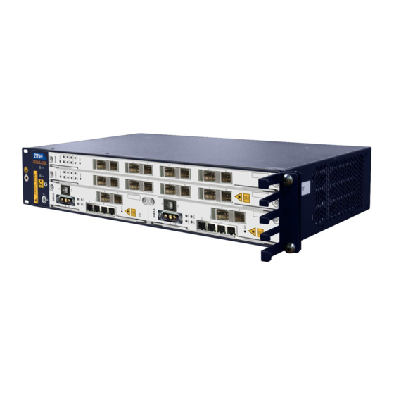
About This Manual Purpose The ZXA10 C320 Optical Access Convergence Equipment (ZXA10 C320 for short) is a 2U-height OLT device, which satisfies the market requirement for small-capacity OLTs. This manual describes the hardware structure of the ZXA10 C320. Intended Audience... - Page 6 SJ-20130520170233-004|2013-08-31 (R1.0) ZTE Proprietary and Confidential...
-
Page 7: Chapter 1 Shelf
Figure 1-2 shows the configurations of the shelf. Figure 1-2 Shelf Configurations Note: When the ZXA10 C320 uses AC power supply, the AC power card PRAM is installed in slot 3. Technical Specifications Table 1-1 lists the technical specifications of the shelf. - Page 8 ZXA10 C320 Hardware Description Table 1-1 Technical Specifications of the Shelf Item Specification Dimensions 86.1 mm × 482.6 mm × 270 mm (height × width × depth) Weight 2.5 kg (empty) 6.9 kg (full configuration) SJ-20130520170233-004|2013-08-31 (R1.0) ZTE Proprietary and Confidential...
-
Page 9: Chapter 2 Cards
Chapter 2 Cards The ZXA10 C320 is composed of cards and a fan unit, see Table 2-1. Table 2-1 Card List Name Description Function Interface SMXA Switching and control Controls the system and One out-of-band Network card switches services. Management (NM) interface... -
Page 10: Smxa Card
Fan Unit ........................2-13 2.1 SMXA Card Overview The switching and control card SMXA is the service switching, management, and control center of the ZXA10 C320. Panel Figure 2-1 shows the panel of the SMXA card. Figure 2-1 The SMXA Panel... - Page 11 The environment monitoring interface The GE electrical interface The GE optical interface The 10GE or GE optical interface -48V/-48VGND The -48 V power socket Buttons Table 2-4 describes the buttons on the SMXA panel. SJ-20130520170233-004|2013-08-31 (R1.0) ZTE Proprietary and Confidential...
- Page 12 ZXA10 C320 Hardware Description Table 2-4 SMXA Buttons Description Button Description ON/OFF To enable/disable the power supply of the equipment To reset the card Principle Diagram Figure 2-2 shows the principle diagram of the SMXA card. Figure 2-2 SMXA Principle Diagram Table 2-5 describes the module functions of switching and control cards.
-
Page 13: Gpon Interface Cards
200.25 mm × 37 mm × 225 mm (height × width × depth) Weight 1.14 kg 2.2 GPON Interface Cards Overview The GPON interface cards provide GPON access. The ZXA10 C320 supports the following GPON interface cards: GTGH: 16-port GPON interface card GTGO: 8-port GPON interface card Panel Figure 2-3Figure 2-4, and Figure 2-4 show the GPON interface card panels. - Page 14 ZXA10 C320 Hardware Description Table 2-7 GPON Interface Cards Indicator Description Indicator Status Description LED is OFF. The card is powered off. The card does not match. is not started. Green LED is ON. The card self-checking completes but fails to receive data from the switching and control card or NM.
- Page 15 Table 2-9 GPON Interface Cards Technical Specifications Item Specification Power consumption GTGH: 55 W GTGO: 30 W Dimensions 395.5 mm × 22.5 mm × 225 mm (Height × Width × Depth) Weight GTGH: 1.000 kg GTGO: 0.925 kg SJ-20130520170233-004|2013-08-31 (R1.0) ZTE Proprietary and Confidential...
-
Page 16: P2P Interface Card
ZXA10 C320 Hardware Description 2.3 P2P Interface Card Overview The FTGK card is a 48-port interface card. It uses technology and single optical fiber for transmitting and receiving. Panel Figure 2-6 shows the FTGK panel. Figure 2-6 FTGK Panel Indicator Table 2-10 describes the indicators of the FTGK card. - Page 17 When the card is used for uplink, the synchronized clock from the optical port is sent to the switching and control card works as the system clock. P2P optical module Provides GE/FE optical interface. SJ-20130520170233-004|2013-08-31 (R1.0) ZTE Proprietary and Confidential...
-
Page 18: Power Card
ZXA10 C320 Hardware Description Technical Specification Table 2-12 lists technical specifications of the FTGK card. Table 2-12 FTGK Technical Specification Item Specification Power consumption 85 W Dimensions 395.5 mm × 22.5 mm × 225 mm (Height × Width × Depth) Weight 1.51 kg... - Page 19 To enable/disable the power supply of the equipment Principle Diagram Figure 2-9 shows the principle diagram of the PRAM card. Figure 2-9 PRAM Principle Diagram Table 2-16 describes functions of each module of the PRAM card. 2-11 SJ-20130520170233-004|2013-08-31 (R1.0) ZTE Proprietary and Confidential...
-
Page 20: Backplane
197.75 mm × 25 mm × 225 mm (Height × Width × Depth) Weight 1.346 kg 2.5 Backplane Overview The ZXA10 C320 uses backplane to connect the cards together. Interfaces The backplane provides the following interfaces: The interface for switching and control card The interface for the... -
Page 21: Fan Unit
Table 2-20 Technical Specifications of the Fan Unit Item Specification Power consumption 20 W Dimensions 84.3 mm × 35.8 mm × 247.9 mm( height × width × depth) Weight 0.425 kg 2-13 SJ-20130520170233-004|2013-08-31 (R1.0) ZTE Proprietary and Confidential... - Page 22 ZXA10 C320 Hardware Description This page intentionally left blank. 2-14 SJ-20130520170233-004|2013-08-31 (R1.0) ZTE Proprietary and Confidential...
-
Page 23: Chapter 3 Cables
Figure 3-1 Power Cable Structure Cable Connection End A of the power cable is connected to the ZXA10 C320 shelf, supplying the power to the shelf. End B of the power cable is connected to the terminal of the power distributor. -
Page 24: Network Cable
ZXA10 C320 Hardware Description 3.2 Network Cable Cable Structure Network cables are cat-5 cables with two ends of RJ45 connectors, see Figure 3-2. Figure 3-2 Network Cable Structure Pin Connections Table 3-2 lists the pin connections of a network cable. -
Page 25: Serial Port Cable
Figure 3-3 Serial Port Cable Structure Pin Connections Table 3-3 lists pin connections of the serial port cable. Table 3-3 Pin Connections of the Serial Port Cable End A End B Note: Other pins are null. SJ-20130520170233-004|2013-08-31 (R1.0) ZTE Proprietary and Confidential... -
Page 26: Fiber Pigtail
ZXA10 C320 Hardware Description 3.4 Fiber Pigtail Cable Description A fiber pigtail is a single short fiber which connects the optical interface or the optical adapter on the ODF. A fiber pigtail has optical connectors at both ends. Connector Description Table 3-4 describes the optical connectors. -
Page 27: Glossary
- Loss Of Signal - Media Access Control - Network Management - Optical Distribution Frame - Point to Point - Power Factor Correction - Passive Optical Network - Quality of Service - Service Level Agreement SJ-20130520170233-004|2013-08-31 (R1.0) ZTE Proprietary and Confidential... - Page 28 ZXA10 C320 Hardware Description - TrafficManagement VLAN - Virtual Local Area Network - Wavelength Division Multiplexing SJ-20130520170233-004|2013-08-31 (R1.0) ZTE Proprietary and Confidential...
Need help?
Do you have a question about the ZXA10 C320 and is the answer not in the manual?
Questions and answers