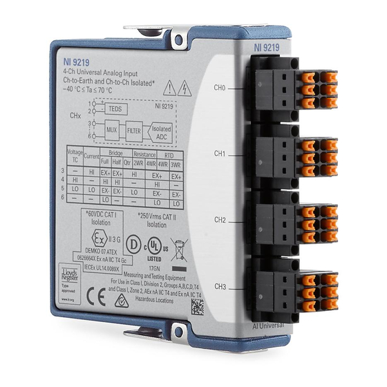
National Instruments NI 9219 Getting Started Manual
4 ai, 100 s/s/ch simultaneous, universal measurements
Hide thumbs
Also See for NI 9219:
- Calibration procedure (50 pages) ,
- Getting started manual (40 pages) ,
- Operating instructions manual (36 pages)

Related Manuals for National Instruments NI 9219


Summary of Contents for National Instruments NI 9219
- Page 1 GETTING STARTED GUIDE NI 9219 4 AI, 100 S/s/ch Simultaneous, Universal Measurements...
-
Page 2: Safety Guidelines
This document explains how to connect to the NI 9219. Before you begin, complete the software and Note hardware installation procedures in your chassis documentation. The guidelines in this document are specific to Note the NI 9219. The other components in the system might not meet the same safety ratings. -
Page 3: Safety Guidelines For Hazardous Voltages
You must use the NI 9972 connector backshell kit to ensure that the terminals are not accessible. NI 9219 Getting Started Guide | © National Instruments | 3... -
Page 4: Safety Voltages
Zone 2 hazardous locations applications in Europe Channel-to-channel 60 VDC, Measurement and channel-to-earth Category I ground Measurement Category I is for measurements performed on circuits not directly connected to the electrical distribution system 4 | ni.com | NI 9219 Getting Started Guide... - Page 5 This category refers to local-level electrical distribution, such as that provided by a standard wall outlet, for example, 115 V for U.S. or 230 V for Europe. NI 9219 Getting Started Guide | © National Instruments | 5...
-
Page 6: Safety Guidelines For Hazardous Locations
IV. Safety Guidelines for Hazardous Locations The NI 9219 is suitable for use in Class I, Division 2, Groups A, B, C, D, T4 hazardous locations; Class I, Zone 2, AEx nA IIC T4 and Ex nA IIC T4 hazardous locations; and nonhazardous locations only. -
Page 7: Special Conditions For Hazardous Locations Use In Europe And Internationally
Zone 2 hazardous locations, in ambient temperatures of -40 °C ≤ Ta ≤ 70 °C. If you are using the NI 9219 in Gas Group IIC hazardous locations, you must use the device in an NI chassis that has been evaluated as Ex nC IIC T4, Ex IIC T4, Ex nA IIC T4, or Ex nL IIC T4 equipment. -
Page 8: Electromagnetic Compatibility Guidelines
To minimize interference with radio and television reception and prevent unacceptable performance degradation, install and use this product in strict accordance with the instructions in the product documentation. 8 | ni.com | NI 9219 Getting Started Guide... -
Page 9: Special Conditions For Marine Applications
In addition, take precautions when designing, selecting, and installing measurement probes and cables to ensure that the desired EMC performance is attained. NI 9219 Getting Started Guide | © National Instruments | 9... -
Page 10: Preparing The Environment
Preparing the Environment Ensure that the environment in which you are using the NI 9219 meets the following specifications. Operating temperature -40 °C to 70 °C (IEC 60068-2-1, IEC 60068-2-2) Operating humidity 10% RH to 90% RH, (IEC 60068-2-78) noncondensing... - Page 11 NI 9219 Pinout NI 9219 Getting Started Guide | © National Instruments | 11...
- Page 12 Table 1. Signals by Mode Mode Voltage — — Current — — 4-Wire Resistance 2-Wire Resistance — — Thermocouple — — 4-Wire RTD 3-Wire RTD — Quarter-Bridge — — Half-Bridge — Full-Bridge 12 | ni.com | NI 9219 Getting Started Guide...
- Page 13 — Table 2. Signal Descriptions Signal Description Positive sensor excitation connection Negative sensor excitation connection Positive input signal connection Negative input signal connection TEDS data connection TEDS COM connection NI 9219 Getting Started Guide | © National Instruments | 13...
-
Page 14: Measurement Types
Measurement Types The NI 9219 provides modes for the following measurement types. • Voltage • Current • 4-Wire Resistance • 2-Wire Resistance • Thermocouple • 4-Wire RTD • 3-Wire RTD • Quarter-Bridge • Half-Bridge • Full-Bridge • Digital In •... -
Page 15: Voltage Connections
Voltage Connections – NI 9219 Related Information Voltage Pinout on page 30 NI 9219 Getting Started Guide | © National Instruments | 15... -
Page 16: Current Connections
Current Connections NI 9219 Related Information Current Pinout on page 30 16 | ni.com | NI 9219 Getting Started Guide... -
Page 17: Thermocouple Connections
Avoid running thermocouple wires near hot or cold objects. • Minimize adjacent heat sources and air flow across the terminals. • Keep the ambient temperature as stable as possible. NI 9219 Getting Started Guide | © National Instruments | 17... - Page 18 • Make sure the NI 9219 terminals are facing forward or upward. • Keep the NI 9219 in a stable and consistent orientation. • Allow the thermal gradients to settle after a change in system power or in ambient temperature. A change in system power can happen when the system powers on, the system comes out of sleep mode, or you insert/remove modules.
- Page 19 4-Wire Resistance and 4-Wire RTD Connections wire wire RTD/ Resistor wire wire NI 9219 Related Information 4-Wire Resistance and 4-Wire RTD Pinout on page 31 NI 9219 Getting Started Guide | © National Instruments | 19...
- Page 20 3-Wire RTD Connections wire wire wire NI 9219 Related Information 3-Wire RTD Pinout on page 32 20 | ni.com | NI 9219 Getting Started Guide...
- Page 21 Full-Bridge Connections wire wire NI 9219 Related Information Full-Bridge Pinout on page 32 NI 9219 Getting Started Guide | © National Instruments | 21...
- Page 22 Half-Bridge Connections wire wire NI 9219 Related Information Half-Bridge Pinout on page 33 22 | ni.com | NI 9219 Getting Started Guide...
- Page 23 CompactRIO systems. Visit ni.com/info and enter the Info Code for information about implementing the 9219cdaq digital in measurement type in CompactDAQ systems. Related Information Digital In Pinout on page 33 NI 9219 Getting Started Guide | © National Instruments | 23...
- Page 24 The open contact measurement type is only supported in CompactRIO systems. Visit ni.com/info and enter the Info Code for information about implementing the 9219cdaq open contact measurement type in CompactDAQ systems. Related Information Open Contact Pinout on page 34 24 | ni.com | NI 9219 Getting Started Guide...
- Page 25 Info Code rdteds NI 9219 Connection Guidelines • Make sure that devices you connect to the NI 9219 are compatible with the module specifications. • Use shielded cables and twisted pair wiring for the best signal quality.
- Page 26 NI 9219 Source • You can connect floating signal sources to the NI 9219. Ensure that the voltages on the HI and LO connections are within the channel-to-earth working voltage range. The following figure illustrates a floating connection for a voltage source.
- Page 27 Flathead screwdriver with a 2.3 mm x 1.0 mm (0.09 in. x 0.04 in.) blade, included with the NI 9219 What to Do Complete the following steps to connect wires to the spring- terminal connector. NI 9219 Getting Started Guide | © National Instruments | 27...
-
Page 28: High-Vibration Application Connections
High-Vibration Application Connections If your application is subject to high vibration, NI recommends that you use the NI 9972 backshell kit to protect connections to the NI 9219. 28 | ni.com | NI 9219 Getting Started Guide... - Page 29 Refer to the device datasheet on ni.com/manuals Note for more information about excitation protection. Measurement Type Pinout The following sections include pinouts for the NI 9219 measurement types. NI 9219 Getting Started Guide | © National Instruments | 29...
- Page 30 Voltage Pinout — — — — Related Information Voltage Connections on page 15 Current Pinout — — — — Related Information Current Connections on page 16 30 | ni.com | NI 9219 Getting Started Guide...
- Page 31 — — — Related Information Thermocouple Connections on page 17 4-Wire Resistance and 4-Wire RTD Pinout — — Related Information 4-Wire Resistance and 4-Wire RTD Connections on page 19 NI 9219 Getting Started Guide | © National Instruments | 31...
- Page 32 3-Wire RTD Pinout — — — Related Information 3-Wire RTD Connections on page 20 Full-Bridge Pinout — — Related Information Full-Bridge Connections on page 21 32 | ni.com | NI 9219 Getting Started Guide...
- Page 33 Half-Bridge Pinout — — — Related Information Half-Bridge Connections on page 22 Digital In Pinout — — — — Related Information Digital In Connections on page 23 NI 9219 Getting Started Guide | © National Instruments | 33...
- Page 34 Open Contact Pinout — — — — Related Information Open Contact Connections on page 24 34 | ni.com | NI 9219 Getting Started Guide...
-
Page 35: Where To Go Next
NI 9219 Datasheet NI-RIO Help NI-DAQmx Help LabVIEW FPGA Help LabVIEW Help RELATED INFORMATION C Series Documentation Services & Resources ni.com/services ni.com/info cseriesdoc Located at ni.com/manuals Installs with the software NI 9219 Getting Started Guide | © National Instruments | 35... -
Page 36: Worldwide Support And Services
(EMC) and product safety. You can obtain the DoC for your product by visiting ni.com/certification. If your product supports calibration, you can obtain the calibration certificate for your product at ni.com/calibration. 36 | ni.com | NI 9219 Getting Started Guide... - Page 37 United States, visit the Worldwide Offices section of ni.com/niglobal to access the branch office websites, which provide up-to-date contact information, support phone numbers, email addresses, and current events. NI 9219 Getting Started Guide | © National Instruments | 37...
- Page 38 U.S. Government Customers: The data contained in this manual was developed at private expense and is subject to the applicable limited rights and restricted data rights as set forth in FAR 52.227-14, DFAR 252.227-7014, and DFAR 252.227-7015. © 2007—2016 National Instruments. All rights reserved. 374473F-01 Apr16...
Need help?
Do you have a question about the NI 9219 and is the answer not in the manual?
Questions and answers