Table of Contents
Advertisement
Copyright
This publication, including all photographs, illustrations and software,
is protected under international copyright laws, with all rights re-
served. Neither this manual, nor any of the material contained herein,
may be reproduced without written consent of the author.
Version 1.1
Disclaimer
The information in this document is subject to change without notice.
The manufacturer makes no representations or warranties with re-
spect to the contents hereof and specifically disclaims any implied
warranties of merchantability or fitness for any particular purpose.
The manufacturer reserves the right to revise this publication and to
make changes from time to time in the content hereof without obliga-
tion of the manufacturer to notify any person of such revision or
changes.
Trademark Recognition
Microsoft, MS-DOS and Windows are registered trademarks of Mi-
crosoft Corp.
MMX, Pentium, Pentium-II, Pentium-III, Celeron are registered
trademarks of Intel Corporation.
Other product names used in this manual are the properties of their
respective owners and are acknowledged.
Preface
Copyright © 2001
All Rights Reserved
KOB 694X FSX
Advertisement
Table of Contents

Related Manuals for Mercury KOB 694X FSX


Summary of Contents for Mercury KOB 694X FSX
- Page 1 Microsoft, MS-DOS and Windows are registered trademarks of Mi- crosoft Corp. MMX, Pentium, Pentium-II, Pentium-III, Celeron are registered trademarks of Intel Corporation. Other product names used in this manual are the properties of their respective owners and are acknowledged. Copyright © 2001 All Rights Reserved KOB 694X FSX...
- Page 2 Federal Communications Commission (FCC) This equipment has been tested and found to comply with the limits for a Class B digital device, pursuant to Part 15 of the FCC Rules. These limits are designed to provide reasonable protection against harmful interference in a residential installation. This equipment gen- erates, uses, and can radiate radio frequency energy and, if not installed and used in accordance with the instructions, may cause harmful interference to radio communications.
- Page 3 Declaration of Conformity This device complies with part 15 of the FCC rules. Operation is sub- ject to the following conditions: − This device may not cause harmful interference, and − This device must accept any interference received, includ- ing interference that may cause undesired operation. Canadian Department of Communications This class B digital apparatus meets all requirements of the Cana- dian Interference-causing Equipment Regulations.
- Page 4 About the Manual The manual consists of the following: Chapter 1 Describes features of the main- board, and provides a shipping Introducing the Mainboard checklist. ⇒ Go to page 1 Chapter 2 Describes installation of main- board components. Installing the Mainboard ⇒...
-
Page 5: Table Of Contents
Preface CHAPTER 1 Introducing the Mainboard Introduction ..................1 Checklist ..................2 Standard Items ..................2 Features...................3 Mainboard Components ..............6 Choosing a Computer Case ............8 CHAPTER 2 Installing the Mainboard Safety Precautions................9 Quick Guide ...................10 Checking Jumper Settings.............11 Setting Jumpers ..................11 Checking Jumper Settings ..............12 Jumper Settings ................. - Page 6 Standard CMOS Features ..............39 Advanced BIOS Setup Option............42 Advanced Chipset Features Option ........... 46 Integrated Peripherals Option............50 Power Management Setup Option ............. 53 PNP/PCI Configuration Option ............60 Frequency Control Option ..............63 Load Fail-Safe Defaults Option............65 Load Optimized Defaults Option ............
-
Page 7: Introducing The Mainboard
Introducing the Mainboard Congratulations on purchasing this mainboard. This main- board is an ATX mainboard that uses a 4-layer printed circuit board and measures 304 mm x 190 mm. The mainboard fea- tures a Socket 370 that accommodates FC-PGA Pentium III, and Cyrix III processors that support frontside bus (FSB) speeds up to 133 MHz. -
Page 8: Checklist
Compare the mainboard’s package contents with the following checklists: Standard Items • One mainboard • One diskette drive ribbon cable and bracket • One IDE drive ribbon cable and bracket • Software support CD • This user’s manual... -
Page 9: Features
Functioning as a platform for a value PC, this Processor mainboard features a Socket 370 that accommo- dates PPGA Celeron, Pentium III, and Cyrix III processors. It supports 66/100/133 MHz FSB speeds. Chipset VIA VT82C694X Northbridge This board features the VIA VT82C694X NB (North Bridge) chipset, enabling synchronous and asynchronous frequency operation between the processor and the memory over a wide frequency... - Page 10 Chipset The integrated Ultra DMA-33/66/100 master mode EIDE controller with enhanced PCI bus com- (continued) mands. The UltraDMA-33/66/100 Master Mode PCI EIDE controller features dual channel master mode PCI supporting Enhanced IDE (EIDE) devices and employ transfer rates up to 33 MB/sec to cover PIO mode 4, multi-word DMA mode 2 drives, and UltraDMA-33 interface.
- Page 11 tential. The PCI slots support Ultra DMA33/66/100 bus mastering with transfer rates up to 33/66/100 MB/sec. Integrated I/O The mainboard has a full set of I/O ports and con- nectors: • Two PS/2 ports for mouse and keyboard • Two serial ports •...
-
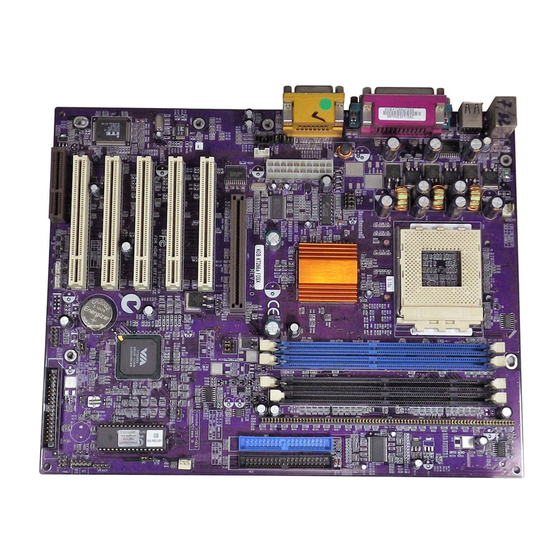
Page 12: Mainboard Components
DIMM2 CPUFAN1 DIMM1 DIMM3 PWRFAN1 CPUFAN1 CPU SOCKET ATX1 DIMM1 DIMM2 DIMM3 AGP1 IDE1 IDE2 PCI1 PCI1 PCI2 PCI2 PCI3 PCI3 PANEL1 PCI4 USB2 PCI4 SIR1 SIR1 USB2 AMR1 FDD1 AMR1 FDD1 ISA1 ISA1 ISA2 ISA2 WOL1 WOM1 WOL1 WOM1... - Page 13 Table of Mainboard Components Label Component AGP1 Accelerated Graphics Port AMR1 Audio modem riser (AMR) slot ATX1 Power connector Three volt realtime clock battery Primary CD-in connector Secondary CD-in connector CPU Socket PGA370 CPU Socket CPUFAN1 Cooling fan for CPU DIMM1 ~ DIMM3 Three 184-pin DIMM sockets FDD1...
-
Page 14: Choosing A Computer Case
There are many types of computer cases on the market. The mainboard complies with the specifications for the ATX sys- tem case. Some features on the mainboard are implemented by cabling connectors on the mainboard to indicators and switches on the system case. Ensure that your case supports all the features required. -
Page 15: Installing The Mainboard
Installing the Mainboard Follow these safety precautions when installing the main- board: • Wear a grounding strip attached to a grounded device to avoid damage from static electricity. • Discharge static electricity by touching the metal case of a safely grounded object before working on the mainboard. -
Page 16: Quick Guide
This Quick Guide suggests the steps you can take to build your system with the mainboards. The following table describes installing specific components: Locating Mainboard Components Go to page 6 Installing Jumpers Go to page 11 Installing the Mainboard in a Case Go to page 15 Go to page 16 Installing Case Components... -
Page 17: Checking Jumper Settings
This section explains how to set jumpers for correct configura- tion of the mainboard. Setting Jumpers Use the mainboard jumpers to set system configuration op- tions. Jumpers with more than one pin are numbered. When setting the jumpers, ensure that the jumper caps are placed on the correct pins. -
Page 18: Checking Jumper Settings
Checking Jumper Settings In the following illustration, only pin 1 is shown. CPUFAN1 DIMM1 DIMM2 DIMM3 PCI1 PCI2 PCI3 PCI4 SIR1 USB2 AMR1 FDD1 ISA1 ISA2 WOL1 WOM1... -
Page 19: Jumper Settings
Jumper Settings Jumper Type Description Setting (default) 3 pin Clear CMOS 1-2: Normal jumper 2-3: Clear CMOS 3 pin BIOS flash 1-2: Unlock protection 2-3: Lock jumper 3 pin Onboard co- 1-2: Onboard codec dec/AMR slot 2-3: AMR slot selector 3 pin AMR Master/ 1-2: Slave AMR... - Page 20 JP1: Clear CMOS Jumper This jumper enables you to reset BIOS: 1. Turn the system off. 2. Short pins 2 and 3 on jumper 1. 3. Return the jumper to the normal setting. 4. Turn the system on. The BIOS is returned to the de- fault settings.
-
Page 21: Installing The Mainboard In A Case
Most system cases have mounting brackets installed in the case, which correspond to the holes in the mainboard. Place the mainboard over the mounting brackets and secure the mainboard into the mounting brackets with screws. Most cases have a choice of I/O templates in the rear panel. Make sure that the I/O template in the case matches the I/O ports installed on the rear edge of the mainboard. -
Page 22: Connecting Case Components
After you have installed the mainboard into a case, you can begin connecting the mainboard components. Refer to the fol- lowing: CPUFAN1 CPUFAN1 PWRFAN1 ATX1 DIMM1 DIMM2 DIMM3 PCI1 PCI2 PCI3 PCI4 SIR1 USB2 AMR1 FDD1 ISA1 ISA2 PANEL1 WOL1 WOM1 1. -
Page 23: The Panel Connector
The Panel Connector The panel connector provides a set of switch and LED con- nectors usually found on ATX or micro-ATX cases. Refer to the table below for information: Device Pins Power switch 22, 23 Power Switch Hard disk LED Indi- +20, -21 (Pins 22, 23) cator... -
Page 24: Installing Hardware
Installing the Processor Caution: When installing a CPU heatsink and cooling fan make sure that you DO NOT scratch the mainboard or any of the surface-mount resistors with the clip of the cooling fan. If the clip of the cooling fan scrapes across the main- board, you may cause serious damage to both the mainboard and the processor. - Page 25 CPU Installation Procedure The following illustration shows CPU installation components: CPU fan Socket 370 Locking lever Pin-1 corner...
- Page 26 Follow these instructions to install the CPU: 1. Pull the CPU socket locking lever away from the socket to unhook it and raise the locking lever to the upright position. 2. Identify the pin A-1 corner on the CPU socket and the pin A-1 corner on the processor.
-
Page 27: Install Memory Modules
Install Memory Modules For this mainboard, you must use 168-pin 3.3V non-buffered Dual In-line Memory Modules (DIMMs). The memory chips must be standard or registered SDRAM and VCM SDRAM memory chips. The memory bus can run at 66 MHz, 100 MHz, or 133 MHz. If your processor operates over a 133 MHz system bus, you can install PC133 or PC100 memory that operates over a 133 or 100 MHz bus. - Page 28 The table below shows maximum memory for DIMMs. DRAM 1 DIMM 2 DIMMs 3 DIMMs Configurations (MB) (MB) (MB) (MB) (MB) 64 Mbit 8M x 8 64 Mbit 4M x 16 16M x 8 Mbit 32M x 4 1024 1536 Mbit SS = Single Sided DS = Double Sided...
-
Page 29: Installing A Hard Disk Drive/Cd-Rom
1. Align the memory module with the slot. The DIMM slots are keyed with notches and the DIMMs are keyed with cutouts so that they can only be installed cor- rectly. Check that the cutouts on the DIMM module edge connector match the notches in the DIMM slot: Latch Cutout Notch... - Page 30 to do this. About UDMA This mainboard supports Ultra DMA 66/100. UDMA is a tech- nology that accelerates the performance of devices in the IDE channel. Install IDE devices that support UDMA and use IDE cables that support UDMA for better performance. Installing a Hard Disk Drive 1.
- Page 31 3. Plug an IDE cable connector into the hard disk drive IDE connector. It doesn't matter which connector on the cable you use. Ensure that the pin-1 side of the cable is matched with the pin-1 side of the connector. Refer to the previous note.
-
Page 32: Installing A Floppy Diskette Drive
Note: Ribbon cable connectors are usually keyed so that they can only be installed correctly on the device connector. If the connector is not keyed, make sure that you match the pin-1 side of the cable connector with the pin-1 side of the device connector. Each connector has the pin-1 side clearly marked. - Page 33 1. Install the FDD into the drive cage in your ATX system case. 2. Plug the FDD cable into FDD1. Pin 1 Note: Ribbon cable connectors are usually keyed so that they can only be installed correctly on the device connector.
-
Page 34: Installing Add-On Cards
When you first start up your system, go immediately to the Setup Utility and use the Standard page to configure the floppy diskette drives that you have installed. See Chapter 3 for more information. Installing Add-on Cards This mainboard has one 4xAGP slot, four PCI slots, two ISA slots and one AMR slot. - Page 35 DIMM1 DIMM2 DIMM3 PCI1 PCI2 PCI3 PCI4 SIR1 USB2 AMR1 FDD1 ISA1 ISA2 WOL1 WOM1 1. Remove a blanking plate from the system case corre- sponding to the slot you are going to use. 2. Install the edge connector of the add-on card into the expansion slot.
-
Page 36: Connecting Optional Devices
Connecting Optional Devices Refer to the following for information on connecting the main- board’s optional devices: CPUFAN1 DIMM1 DIMM2 DIMM3 USB2 PCI1 PCI2 PCI3 PCI4 SIR1 USB2 AMR1 FDD1 SIR1 ISA1 ISA2 WOL1 WOM1 WOL1 WOM1... - Page 37 USB2: USB port The mainboard has one USB port installed on the rear edge I/O port array. However, some computer cases have a special module that mounts USB ports at the front of the case. If you have this kind of case, use auxiliary USB connectors on USB2 to connect the front-mounted ports to the mainboard.
- Page 38 SIR1: Serial infrared port The mainboard supports a Serial Infrared (SIR) data port. In- frared ports allow the wireless exchange of information between your computer and similarly equipped devices such as printers, laptops, Personal Digital Assistants (PDAs), and other computers. Signal Name IRRX Ground...
-
Page 39: Connecting I/O Devices
The backplane of the mainboard has a full set of I/O ports: Parallel port (LPT1) Game port PS/2 mouse PS/2 Serial port Serial port Microphone keyboard ports COM 1 COM 2 Line-in Line-out 1. Use the upper PS/2 port to connect a PS/2 pointing device. -
Page 40: External Connector Color Coding
External Connector Color Coding Many connectors now use standard colors as shown in the table below. Connector Color Analog VGA Blue Audio line-in Light blue Audio line-out Lime Digital monitor / flat panel White IEEE 1394 Grey Microphone Pink MIDI/Game Gold Parallel Burgundy... -
Page 41: Using Bios
Using BIOS The computer employs the latest Award BIOS CMOS chip with support for Windows Plug and Play. This CMOS chip con- tains the ROM setup instructions for configuring the mainboard’s BIOS. The BIOS (Basic Input and Output Sys- tem) Setup Utility is a ROM-based configuration utility that displays the system’s configuration status and provides you with a tool to set system parameters. -
Page 42: The Standard Configuration
The Standard Configuration A standard configuration has already been set in the Setup Utility. However, we recommend that you read this chapter in case you need to make any changes in the future. This program should be executed under the following condi- tions: •... -
Page 43: Entering The Setup Utility
Entering the Setup Utility When you power on the system, BIOS enters the Power-On Self Test (POST) routines. POST is a series of built-in diag- nostics performed by the BIOS. After the POST routines are completed, the following message appears: Press DEL to enter SETUP Pressing the delete key accesses the Award BIOS Setup... -
Page 44: Updating The Bios
Updating the BIOS You can download and install updated BIOS for this main- board from the manufacturer's web site. New BIOS provides support for new peripherals, improvements in performance, or fixes for known bugs. Install new BIOS as follows: 1. If your mainboard has a BIOS protection jumper, change the setting to allow BIOS flashing. -
Page 45: Using Bios
When you start the Setup Utility, the main menu appears. The main menu of the Setup Utility displays a list of the options that are available. A highlight indicates which option is cur- rently selected. Use the cursor arrow keys to move the highlight to other options. - Page 46 Date and Time The Date and Time items show the current date and time held by your computer. If you are running a Windows OS, these items are automatically updated whenever you make changes to the Windows Date and Time Properties utility. IDE Devices (None) Your computer has two IDE channels (Primary and Secon- dary) and each channel can be installed with one or two...
- Page 47 fer to your drive’s documentation or look on the drive if you need to obtain this information. If no device is installed, change the value to None. Note: Before attempting to configure a hard disk drive, ensure that you have the configuration information supplied by the manufacturer of your hard drive.
-
Page 48: Advanced Bios Setup Option
Advanced BIOS Setup Option This option displays a table of items that define advanced in- formation about your system. CMOS Setup Utility – Copyright (C) 1984 – 2001 Award Software Advanced BIOS Features Anti-Virus Protection Disabled Item Help Y2K Monitor Disabled CPU Internal Cache Enabled... - Page 49 External Cache (Enabled) Most processors that can be installed in this system use ex- ternal level 2 (L2) cache memory to improve performance. CPU L2 Cache ECC Checking (Enabled) This item enables or disables ECC (Error Correction Code) er- ror checking on the CPU cache memory. We recommend that you leave this item at the default value.
- Page 50 Boot Up Floppy Seek (Enabled) If this item is enabled, it checks the geometry of the floppy disk drives at start-up time. You don’t need to enable this item unless you have a legacy diskette drive with 360K capacity. Boot Up NumLock Status (On) This item defines if the keyboard Num Lock key is active when your system is started.
- Page 51 Technology) system is a diagnostics technology that monitors and predicts device performance. S.M.A.R.T. software resides on both the disk drive and the host computer. The disk drive software monitors the internal performance of the motors, media, heads, and electronics of the drive. The host software monitors the overall reliability status of the drive.
-
Page 52: Advanced Chipset Features Option
Advanced Chipset Features Option This option displays a table of items that define critical timing parameters of the mainboard. You should leave the items on this page at their default values unless you are very familiar with the technical specifications of your system hardware. If you change the values incorrectly, you may introduce fatal er- rors recurring... - Page 53 Memory Hole (Disabled) This item can be used to reserve memory space for some ISA expansion cards that require it. P2C/C2P Concurrency (Enabled) When disabled, the CPU bus is occupied during the entire PCI operation period. Fast R-W Turn Around (Disabled) When this is enabled, the chipset will insert one extra clock to the turn-around of back-to-back DRAM cycles.
- Page 54 AGP Fast Write (Disabled) This item allows you to enable or disable the caching of dis- play data for the video memory of the processor. Enabling can greatly improve the display speed. If your graphics display card does not support this feature, you need to disable this item OnChip USB (Enabled) This should be enabled if your system has a USB installed on...
- Page 55 Bus (PCI#1) is executed with the error retry feature. AGP Master 1 WS Write (Disabled) This implements a single delay when writing to the AGP Bus. By default, two-wait states are used by the system, allowing for greater stability. AGP Master 1 WS Read (Disabled) This implements a single delay when reading to the AGP Bus.
-
Page 56: Integrated Peripherals Option
Integrated Peripherals Option This option displays a list of items that defines the operation of peripheral components on the system's input/output ports. CMOS Setup Utility – Copyright (C) 1984 – 2000 Award Software Integrated Peripherals OnChip IDE Channel0 Enabled Item Help OnChip IDE Channel1 Enabled... - Page 57 IDE Primary/Secondary Master/Slave UDMA (Auto) Each IDE channel supports a master device and a slave device. This mainboard supports UltraDMA. UltraDMA technology provides faster access to IDE devices. If you install a device that supports UltraDMA, change the ap- propriate item on this list to Auto. You may have to install the UltraDMA driver supplied with this mainboard in order to use an UltraDMA device.
- Page 58 IR Function Duplex (Half) This field is available when UART 2 Mode is set to either ASKIR or HPSIR. This item enables you to determine the infrared (IR) function of the onboard infrared chip. The options are Full and Half (default). Full-duplex means that you can transmit and send information simultaneously.
- Page 59 Onboard Legacy Audio (Enable) Enables the onboard legacy audio function. If this item is en- abled the following items become available. Sound Blaster (Disabled) Enables or disables Sound Blaster function. SB I/O Base Address (220H) This item lets you set the I/O base address for the Sound Blaster card.
-
Page 60: Power Management Setup Option
Power Management Setup Option This option displays items that let you control the system power management. Modern operating systems take care of much of the power management. This mainboard supports ACPI (Advanced Configuration and Power Interface). The sys- tem has various power saving modes including powering down the hard disk, turning off the video, suspending to RAM, and a software power down that allows the system to be automatically resumed by certain events. - Page 61 ACPI Function (Enabled) This mainboard supports ACPI (Advanced Configuration and Power management Interface). Use this item to enable or dis- able the ACPI feature. Note: ACPI is a power management specification that makes hardware status information available to the operating system. ACPI enables a PC to turn its pe- ripherals on and off for improved power management.
- Page 62 HDD Power Down (Disable) The IDE hard drive will spin down if it is not accessed within a specified length of time. Options are from 1 Min to 15 Min and Disable. Doze Mode (Disabled) The system speed will change from turbo to slow if no Power Management events occur for a specified length of time.
- Page 63 Soft-Off by PWRBTN (Instant-Off) Under ACPI (Advanced Configuration and Power manage- ment Interface) you can create a software power down. In a software power down, the system can be resumed by Wake Up Alarms. This item lets you install a software power down that is controlled by the normal power button on your system.
- Page 64 LPT & COM (LPT/COM) When this item is enabled, the system will restart the power- saving timeout counters when any activity is detected on the serial ports, or the parallel port. HDD & FDD (On) When this item is enabled, the system will restart the power- saving timeout counters when any activity is detected on the hard disk drive or the floppy diskette drive.
- Page 65 IRQ/Event Activity Detect Scroll to this item and press <Enter> to view the following screen: CMOS Setup Utility – Copyright (C) 1984 – 2000 Award Software IRQ/ Activity Detect IRQ 3 (COM2) Enabled Item Help IRQ 4 (COM1) Enabled IRQ 5 (LPT2) Enabled Menu Level...
-
Page 66: Pnp/Pci Configuration Option
PNP/PCI Configuration Option This option displays a table of items that configures how PnP (Plug and Play) and PCI expansion cards operate in your sys- tem. Both the ISA and PCI buses on the Mainboard use system IRQs (Interrupt ReQuests) and DMAs (Direct Memory Access). - Page 67 If you cannot get a legacy ISA (Industry Standard Architecture) expansion card to work properly, you might be able to solve the problem by changing this item to Manual, and then open- ing up the IRQ Resources and Memory Resources submenus. In the IRQ Resources submenu, if you change any of the IRQ assignations to Legacy ISA, then that Interrupt Request Line is reserved for a legacy ISA expansion card.
- Page 68 PCI Health Status Option On mainboards that support hardware monitoring, this item lets you monitor the parameters for critical voltages, critical temperatures, and fan speeds. You cannot make any changes to these fields. They are for display only: CMOS Setup Utility – Copyright (C) 1984 – 2001 Award Software PC Health Status Item Help Shutdown Temperature...
-
Page 69: Frequency Control Option
• Power supply’s ±12 volt Frequency Control Option This item enables you to set the clock speed and system bus for your system. The clock speed and system bus are deter- mined by the kind of processor you have installed in your system. - Page 70 For example, if you have a processor that is rated to run at 450 MHz and the system is running a frontside bus frequency of 100 MHz, you should select a multiplier of 4.5 so that: 4.5 (Multiplier) x 100 MHz (frontside bus) = 450 MHz (CPU clock) CPU clock failed reset (Disabled) When this item is enabled and the system crashes three times...
-
Page 71: Load Fail-Safe Defaults Option
Load Fail-Safe Defaults Option This option opens a dialog box that lets you install fail-safe de- faults for all appropriate items in the Setup Utility: Press <Y> and then <Enter> to install the defaults. Press <N> and then <Enter> to not install the defaults. The fail-safe de- faults place no great demands on the system and are generally stable. -
Page 72: Set Supervisor And User Passwords Options
Set Supervisor and User Passwords Options These items can be used to install a password. A Supervisor password takes precedence over a User password, and the Supervisor can limit the activities of a User. To install a pass- word, follow these steps: 1. -
Page 73: Save & Exit Setup Option
Save & Exit Setup Option Highlight this item and press <Enter> to save the changes that you have made in the Setup Utility and exit the Setup Utility. When the Save and Exit dialog box appears, press <Y> to save and exit, or press <N> to return to the main menu: Exit Without Saving Highlight this item and press <Enter>... -
Page 74: Using The Mainboard Software
Using the Mainboard Software The support software CD-ROM that is included in the main- board package contains all the drivers and utility programs needed to properly run the bundled products. For this board, you can install software from the following folders: IDE Folder You can use the software in this folder to install VIA IDE driver for your operating system. -
Page 75: Ide Folder Installation Notes
You can use the software in this folder to install VIA IDE driver for your operating system. Use the SETUP.EXE application in the \VIA\IDE folder. This folder has software and drivers for the Realtek codec sound system that is integrated on this mainboard. The Real- tek codec allows the system to generate optimal sound effects. -
Page 76: Utility Folder Installation Notes
Award Flash Memory Utility This utility lets you erase the system BIOS stored on a Flash Memory chip on the mainboard, and lets you copy an updated BIOS to the chip. Take care how you use this program. If you erase the current BIOS and fail to write a new BIOS, or write a new BIOS that is incorrect, your system will malfunction. -
Page 77: Recovery Genius
Recovery Genius The Recovery Genius software program is an innovative win- dows application system that protects your Hard Disk Drive from virus intrusion, accidental deletions and from system cor- ruption. To install the Recovery Genius software program run SETUP.EXE from the following directory: \UTILITY\RECOVERY GENIUS\ENG\RECOVERYGENIUS WinDVD (optional) Go to the directory \UTILITY\WINDVD;... -
Page 78: Setting Jumpers
Setting Jumpers Jumper Settings Jumper Type Description Setting (default) 3 pin Clear CMOS 1-2: Normal jumper 2-3: Clear CMOS 3 pin BIOS flash 1-2: Unlock protection 2-3: Lock jumper 3 pin Onboard co- 1-2: Onboard co- dec/AMR slot selector 2-3: AMR slot 3 pin AMR Master/ 1-2: Slave AMR... - Page 79 JP1: Clear CMOS Jumper This jumper enables you to reset BIOS: 1. Turn the system off. 2. Short pins 2 and 3 on jumper 1. 3. Return the jumper to the normal setting. 4. Turn the system on. The BIOS is returned to the de- fault settings.
-
Page 80: The Panel Connector
The Panel Connector The panel connector provides a set of switch and LED con- nectors usually found on ATX or micro-ATX cases. Refer to the table below for information: Device Pins Power switch 22, 23 Power Switch Hard disk LED Indi- +20, -21 (Pins 22, 23) cator...
Need help?
Do you have a question about the KOB 694X FSX and is the answer not in the manual?
Questions and answers