
Related Manuals for Lenovo ThinkSystem HR650X


Summary of Contents for Lenovo ThinkSystem HR650X
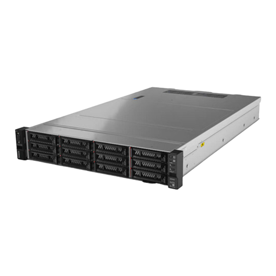
- Page 1 ThinkSystem HR650X User Guide and Hardware Maintenance Manual V1.0 Please read this manual before using the product...
-
Page 2: Table Of Contents
Content Disclaimer ................................7 Trademarks and Copyrights ..........................8 Safety Information ............................9 Chapter 1 Introduction ........................... 13 1.1 PRODUCT OVERVIEW ..........................13 1.2 FEATURES ............................. 13 1.2.1 HIGH RELIABILITY ........................... 13 1.2.2 HIGHLY AVAILABILITY ........................13 1.2.3 HIGH EXPANDABILITY ........................13 1.2.4 HIGH MANAGEABILITY ........................13 1.3 FEATURES AND SPECIFICATIONS ...................... - Page 3 3.3 Main Menu ............................37 Chapter 4. BMC Setup ............................ 78 4.1 Overview of the Lenovo ThinkSystem Management Module ..............78 4.2 Configuration of the ThinkSystem Remote Management Module ............79 4.3 ThinkSystem Remote Management Module Quick Start ............... 80 Prestart ..............................
- Page 4 4.7.1 Field Replaceable Unit(FRU) Information ..................90 4.8 Logs & Reports ............................91 4.8.1 IPMI Event Log ..........................91 4.8.2 System Log ............................. 92 4.8.3 Audit Log ............................92 4.8.4 Video Log ............................93 4.9 Settings ..............................93 4.9.1 Date & Time ........................... 94 4.9.2 External User Services ........................
- Page 5 4.13.5 Restore Configuration ........................ 108 Chapter 5. Troubleshooting and diagnostics ....................109 5 . 1 PROBLEMS WITH INITIAL START UP ....................109 5 . 2 APPLICATION PROGRAM PROBLEMS ....................109 5. 3 SYSTEM OPERATION PROBLEMS......................109 5 . 4 RESOLVING OTHER PROBLEMS ......................110 5.4.1 MONITOR DISPLAY PROBLEMS .....................
-
Page 7: Disclaimer
Product and the contents of this manual, or should you wish to find out the latest information or to send us your questions or comments, please call our service hotline or visit the Lenovo service website. -
Page 8: Trademarks And Copyrights
Trademarks and Copyrights Legend, Lenovo, Lenovo 联想 , ThinkServer, and For Those Who Do characters and logos are either registered trademarks or trademarks of the Lenovo Group in the P.R.C. and/or other countries or regions. Celeron, Celeron Inside, Centrino, Centrino Inside, Core Inside, Intel, the Intel logo, Intel Atom, Intel Atom Inside, Intel Core, Intel Inside, Intel Inside Logo, Intel Viiv, Intel vPro, Itanium, Itanium Inside, Pentium, Pentium Inside, Viiv inside, vPro Inside, Xeon and Xeon Inside are trademarks of the Intel Corporation in the United States or other countries. -
Page 9: Safety Information
Safety Information IMPORTANT: Each caution and danger statement in this document is labeled with a number. This number is used to cross reference an English-language caution or danger statement with translated versions of the caution or danger statement in the Safety Information document.For example, if a caution statement is labeled “StatementInformationdocumentunder1”, tra “Statement 1.”... - Page 10 CAUTION: When laser products (such as CD-ROMs, DVD drives, fiber optic devices, or transmitters) are installed, note the following: •Do not remove the covers. Removing the covers of laser products may result in exposure to hazardous laser radiation.There are no serviceable parts inside these devices.
- Page 11 CAUTION: Never remove the cover on a power supply or any part that has the following label attached. Hazardous voltage, current, and energy levels are present inside any component that has this label attached. There are no serviceable parts inside these components.
- Page 12 Statement 16 CAUTION: To reduce the risk of electric shock or energy hazards: •This equipment must be installed by trained service personnel in a restricted-access location, as defined by your local electrical code and the latest edition of IEC 60950. •Connect the equipment to a reliably grounded safety extra low voltage (SELV) source.
-
Page 13: Chapter 1 Introduction
Chapter 1 Introduction This chapter gives you an overview of the ThinkServer HR650X and briefly describes its features, specifications and functions. 1.1 PRODUCT OVERVIEW The ThinkServer HR650X is a low-cost, 2U, two-socket server that features the latest Intel Xeon Skylake Server 2S processors and supports up to 24 DDR4 DIMMs. -
Page 14: Features And Specifications
Lenovo. Supported Altitude* (unpressurized): 0-10000ft (0-3050m) Altitude A2: Operating temperature de-rated 1°C per 300m (1000ft) to 3050m (10000ft) above sea level, No A3/A4 support Ambient System support ASHARE A2, and A3, A4 with limitation... - Page 15 A2 - Derate maximum allowable dry-bulb temperature 1°C/300 m above 900 m. A3 - Derate maximum allowable dry-bulb temperature 1°C/175 m above 900 m. A4 - Derate maximum allowable dry-bulb temperature 1°C/125 m above 900 m. Please refer ASHRAE standard Temperature: -40℃...
-
Page 16: Chapter 2 Structural Characteristics
Note: The following procedures should only be performed by qualified operators or service personnel trained in server maintenance. Do not perform any removal procedure until you have read and understood all warnings and cautions stated in the "Lenovo Server User Guide - Read Me First"... -
Page 17: Rear View Of The Server
2.1.2 REAR VIEW OF THE SERVER Rear views of the server 1. Half high half length PCIe card slot 2. Full high half length PCIe card slot 3. Hot-swap power supply 1 4. Hot-swap power supply 2(optional) 5. Serial connector 6. - Page 18 Front control panel 1. Steady green light: the server is on 1. Power button with power status LED 2. Off: the server is off 3.Blinking green: the server is DC off 1. Steady blue light: the server is identified 2. System ID button with ID LED 2.
-
Page 19: Mb Assembly Main Components
2.1.4 MB ASSEMBLY MAIN COMPONENTS 2.2 INSTALLING, REMOVING AND REPLACING HARDWARE Safety Precautions Read and follow all safety precautions specified in "Read Me First". If the instructions provided with the server differs from the instructions contained in this manual, contact a service technician from the supplier to confirm the correct procedures. Note: The power button does not completely turn off the AC current supplied to the device. -
Page 20: Exploded Drawing
2.2.1 EXPLODED DRAWING 1. Server cover 2. Riser2 cage 3. Riser1 cage 4. M.2 module 5. Rear back plane 6. Supercap 7. OCP shroud 8. OCP Mezz card 9. PSU 10. Rear 3.5-inch HDD module t 11. Chassis 12. MB Assembly 13. -
Page 21: Removing And Reinstalling The Rack Handle
2.2.2 REMOVING AND REINSTALLING THE RACK HANDLE Do not proceed before reading and understanding the "Safety Precautions" section of this chapter and "Read Me First". To remove the rack handle, do the following: 1. Turn off all attached devices and the server 2. -
Page 22: Removing And Reinstalling The Back Plane
Removing the cooling shroud To reinstall, reverse the steps above. 2.2.5 REMOVING AND REINSTALLING THE BACK PLANE Do not proceed before reading and understanding the "Safety Precautions" section of this chapter and "Read Me First". To remove a back plane, do the following: 1. -
Page 23: Removing Or Installing A Memory Module
To reinstall, reverse the steps above. 2.2.7 REMOVING OR INSTALLING A MEMORY MODULE Do not proceed before reading and understanding the "Safety Precautions" section of this chapter and "Read Me First". To install a memory module, do the following: 1. Turn off all attached devices and the server. 2. -
Page 24: Replacing The Riser 1, 2
2.2.8 REPLACING THE RISER 1, 2 Do not proceed before reading and understanding the "Safety Precautions" section of this chapter and "Read Me First". To remove the Riser 1, 2, Rear HDD module assembly, do the following: 1. Turn off all attached devices and the server. 2. -
Page 25: Removing Or Installing A Pcie Card
2.2.9 REMOVING OR INSTALLING A PCIE CARD Do not proceed before reading and understanding the "Safety Precautions" section of this chapter and "Read Me First". To remove a PCIe card on riser module, do the following: 1. Turn off all attached devices and the server. 2. - Page 26 1. Lift up the PCIe cage module from chassis 2. Use screwdriver to release the screws on the PCIe cage 3. Pull out the PCIe cage To remove GPU card 1. Lift up the riser module 2. Pull out the plastic supporter (Step 1) 3.
-
Page 27: Removing Or Installing The Rear Hdd Module
Installation slots for PCIe cards 2.2.10 REMOVING OR INSTALLING THE REAR HDD MODULE Do not proceed before reading and understanding the "Safety Precautions" section of this chapter and "Read Me First". To remove Rear HDD module assembly, do the following: 1. -
Page 28: Installing Or Replacing A Ocp Card
6. Install the heat sink with CPU onto the socket 7. Screw the heat sink with torque screwdriver and following the sequence in figure Note: Do not touch the pins on the CPU socket to avoid damaging them. To install the CPU dummy, Align to DIMM slots and push down the CPU dummy. To remove, reverse the steps above. -
Page 29: Installing Or Replacing The Dummy Tray For A Hot-Swap Drive
5. Turn off all attached devices and the server. 6. Disconnect the AC power cord from the electrical outlet. 7. Remove the server cover. (See "Removing and reinstalling the server cover") 8. Use screw drive to release the OCP card bracket screw (Step1) and remove the bracket (Step2). 9. - Page 30 Removing the dummy tray of a 3.5-inch dummy tray To reinstall, reverse the steps above.
-
Page 31: Installing Or Replacing A Hot-Swap Drive
2.2.14 INSTALLING OR REPLACING A HOT-SWAP DRIVE Do not proceed before reading and understanding the "Safety Precautions" section of this chapter and "Read Me First". Note: The diagrams below are relevant for servers with 3.5-inch hard drive configuration only. To remove a 3.5-inch hot-swap drive, do the following: 1. -
Page 32: Installing Or Replacing A Hot-Swap Power Supply
2.2.15 INSTALLING OR REPLACING A HOT-SWAP POWER SUPPLY Do not proceed before reading and understanding the "Safety Precautions" section of this chapter and "Read Me First". 1. Slide the hot-swap power supply into the chassis until it snaps into position. 2. -
Page 33: Installing Or Replacing A System Fan Cage
2.2.17 INSTALLING OR REPLACING A SYSTEM FAN CAGE Do not proceed before reading and understanding the "Safety Precautions" section of this chapter and "Read Me First". To remove a system fan cage, do the following: 1. Remove the server cover. (See "Removing and reinstalling the server cover") 2. - Page 34 4. Remove the server cover. (See "Removing and reinstalling the server cover") 5. Insert the M.2 storage module through the guide pins between the PSU cage and left Riser2 6. Plugs the SATA cable and power cable to SATA port 0/1 and power connector To reinstall, reverse the steps above.
-
Page 35: Removing The Main Board
To install 1. Handle the MB assembly through grabbing the plungers & handle (position 1, 2) 2. Align to location pin (Position 3) on chassis and put down the MB assembly 3. Slide to back side © Copyright Lenovo 2017... -
Page 36: Installing The Rail Kit
Warning: Installation of the rail kit should be performed by two or more people. Some risk is involved when moving and installing the server. Be sure to follow the instructions provided in the "Rail Kit Installation Guide" closely. © Copyright Lenovo 2017... -
Page 37: Chapter 3. Bios Setup
Read Only Display Build Date and Time ME Version Read Only Display ME Version ME Current State Read Only Display ME Current State BMC Version Read Only Display BMC Version IPMI Version Read Only Display IPMI Version © Copyright Lenovo 2017... - Page 38 Display current L1 Cache L2 Cache RAM Read Only Display current L2 Cache L3 Cache RAM Read Only Display current L3 Cache Processor Socket Read Only Display Processor Socket2 Socket3 Processor ID Read Only Display current Processor ID © Copyright Lenovo 2017...
- Page 39 Drivers/Controllers Trusted Computing #In Trusted Computing Table Trusted Conputing Settings Serial Port Console Redirection #In Serial Port Console Redirection Serial Port Console Redirection Table PCI SubsystemSettings #In PCI SubsystemSettings Table PCI, PCI-X and PCI Express Settings. © Copyright Lenovo 2017...
- Page 40 Intel@ Virtual RAID on CPU Table(Sub of Item Description Intel(R) RSTe RAID 5.0.0.1116 Driver One Blank line No RAID volumes on the system One Blank Line All VMD controllers Select to see more information about the VMD © Copyright Lenovo 2017...
- Page 41 AST2500 Super IO Configuration One Blank Line COM0 Configuration Serial Port Disabled/Enabled Enable or Disable Serial Port (COM) Device Settings IO=3F8h; IRQ=4; Change Settings Auto Select an optimal settings for Super IO Device IO=3F8h; IRQ=4; IO=3F8h; IRQ=3,4,5,6,7,9,10,11,12 IO=2F8h; © Copyright Lenovo 2017...
- Page 42 COM0(SOL) Console Redirection Settings One Blank Line Terminal Type VT100/VT100+/VT- Emulation: ANSI: Extended ASCII char set. VT100: UTF8/ANSI ASCII char set. VT100+: Extends VT100 to support color, function keys, etc. VT-UTF8: Uses UTF8 © Copyright Lenovo 2017...
- Page 43 The Settings specify if BootLoader is selected then POST Enable/BootLoader Legacy console redirection is disabled before booting to Legacy OS. Default value is Always Enable which means Legaacy console Redirection is enabled for Legacy OS. One Blank Line COM1 © Copyright Lenovo 2017...
- Page 44 Once the buffers are empty, a 'start' signal can be sent to re-start the flow. Hardware flow control uses two wires to send start/stop signals. VT-UTF8 Disabled/En Enable VT-UTF8 Combination Key Support for Combo Key abled ANSI/VT100 terminals Support © Copyright Lenovo 2017...
- Page 45 Terminal VT100/VT1 VT-UTF8 is the preferred terminal type for out-of- Type 00+/VT- band management. The next best choice is VT100+ UTF8/ANSI and then VT100. See above, in Console Redirection Settings page, for more Help with Terminal © Copyright Lenovo 2017...
- Page 46 Ipv4 PXE Support Disabled/Enabled Enable Ipv4 PXE Boot Support. If disabled IPV4 PXE boot option will not be created Ipv4 HTTP Support Disabled/Enabled Enable Ipv4 HTTP Boot Support. If disabled IPV4 HTTP boot option will not be created © Copyright Lenovo 2017...
- Page 47 POSTPONED - execute the trap during legacy boot. One blank line Boot option filter UEFI and Legacy This option controls Legacy/UEFI ROMs priority Legacy only UEFI only One blank line Option ROM execution One blank line © Copyright Lenovo 2017...
- Page 48 Mice, 1 Point, 4 hub One blank line Legacy USB Support Enabled/Disabled/Auto Enables Legacy USB support. AUTO option disables legacy support if no USB devices are connected. DISABLE option will keep USB devices available only for EFI applications. © Copyright Lenovo 2017...
- Page 49 #5 Disable BIOS or OS. USB HS Disable/Ena Enable/Disable this USB Physical Connector Physical (physical port). Once disabled, any USB devices Connector plug into the connector will not be detected by © Copyright Lenovo 2017...
- Page 50 CD-ROM a drive type. AMI Virtual HDisk0 1.00 Auto Mass storage device emulation type. 'AUTO' Floppy enumerates devices according to their media Forced FDD format. Optical drives are emulated as 'CDROM', © Copyright Lenovo 2017...
- Page 51 Recommended to be enabled. Energy Performance Performance/Balanced Set Energy Performance BIAS,which overrides OS BIAS setting. Performance/Balanced setting. Power/Power Advanced Menu ACPI Configuration Table(Sub of ACPI Configuration System ACPI Parameters. One blank line Power Button Lock/Unlock Power Button Lock/Unlock © Copyright Lenovo 2017...
- Page 52 Auto decides based on Si Compatibility. QPI Link L1 Enable Disable/Enable Enable - Set the c_l1_en, Disable - Reset it, Auto - Auto decides based on Si Compatibility. Link Frequency Select 9.6GB/s Allows for selecting the UPI Link Frequency © Copyright Lenovo 2017...
- Page 53 Disable / Select Dma Enable/Disable for each CB device Enable No Snoop Disable No Snoop Enable/Disable for each CB device Enable IOAT Function 4 Items ==================== ================ Disable / Select Dma Enable/Disable for each CB device Enable © Copyright Lenovo 2017...
- Page 54 No Snoop Disable No Snoop Enable/Disable for each CB device Enable IOAT Function 1 Items ==================== ================ Disable / Select Dma Enable/Disable for each CB device Enable No Snoop Disable No Snoop Enable/Disable for each CB device © Copyright Lenovo 2017...
- Page 55 No Snoop Enable/Disable for each CB device Enable IOAT Function 6 Items ==================== ================ Disable / Select Dma Enable/Disable for each CB device Enable No Snoop Disable No Snoop Enable/Disable for each CB device Enable IOAT Function 7 Items ==================== ================ © Copyright Lenovo 2017...
- Page 56 Control to enable/disable IOAT devices Intel VT for Directed I/O Enable/Disabled Enable/Disable Intel Virtualization Technology for (VT-d) Directed I/O (VT-d) by reporting the I/O device assignment to VMM through DMAR ACPI Tables. Advanced Menu SATA Configuration Table(Sub of © Copyright Lenovo 2017...
- Page 57 Designates this port as Hot Pluggable. SATA Port 3 [Not Installed] Hot Plug Disable /Enable Designates this port as Hot Pluggable. SATA Port 4 [Not Installed] Hot Plug Disable /Enable Designates this port as Hot Pluggable. SATA Port 5 [Not Installed] © Copyright Lenovo 2017...
- Page 58 If rank sparing is enabled Mirror Mirror partial mirroring will not take effect. Mirror Enable mode 1LM will disable XPT Prefetch Partial Mirror mode 2LM Memory Disable/Ena Enable/Disable Memory Rank Sparing Rank Sparing © Copyright Lenovo 2017...
- Page 59 4200-OvrClk 4266-OvrClk 4400-OvrClk Numa Disable/Enable Enable or Disable Non uniform Memory Access (NUMA). Disable/Enable/Auto Sub NUMA Clustering is almost equal to cluster on die,automatically support 1-cluster or 2-cluster based on IMC interleave. Memory Thermal Memory Thermal © Copyright Lenovo 2017...
- Page 60 Auto / Disable /Enable In auto mode the BIOS twill remove the EXP port if there is no device or errors on that device and the device is not HP capable. Disable is used to disable © Copyright Lenovo 2017...
- Page 61 HP capable. Disable is used to disable Link Speed Auto Choose Link Speed for this PCIe port Gen 1 (2.5 GT/s) Gen 2 (5 GT/s) © Copyright Lenovo 2017...
- Page 62 Gen 3 (8 GT/s) Socket 1 PcieBr2D00F0 - Port 2A PCI-E Port Auto / Disable /Enable In auto mode the BIOS twill remove the EXP port if there is no device or errors on that device and the © Copyright Lenovo 2017...
- Page 63 In auto mode the BIOS twill remove the EXP port if there is no device or errors on that device and the device is not HP capable. Disable is used to disable Link Speed Auto Choose Link Speed for this PCIe port Gen 1 (2.5 GT/s) © Copyright Lenovo 2017...
- Page 64 In PILOTII, BMC starts at the same time when BIOS starts during AC power ON. It takes around 30 seconds to initialize Host to BMC FRB-2 Timer Enabled/Disabled Enable or Disable FRB-2 timer(POST timer) © Copyright Lenovo 2017...
- Page 65 Event Log Records. BMC User Settings #In BMC User Settings Table Press <Enter> to Add, Delete and Set Privilege level for users. SOL Configuration Parameter #In SOL Configuration Parameter Press <Enter> to Configure SOL Table Configuration Parameters. © Copyright Lenovo 2017...
- Page 66 If bonding mode, hide the item. FQDN/Hostname One blank line Domain Name Configuration Domain Settings Manual/shared_v4/shar ed_v6/dedicated_v4/de dicated_v6 Domain Name usi.com.tw Based on BMC setting One blank line Domain Name Server Configuration DNS Server Settings Manual/shared/dedicate IP Proiority IPv4/IPv6 © Copyright Lenovo 2017...
- Page 67 / Do not log Select the action to be taken when log is full any more DATE TIME STATUS CODE Server Management Menu View FRU information(Sub of View FRU information Press <Enter> to view FRU information. FRU Information © Copyright Lenovo 2017...
- Page 68 One blank line Lan channel 1 Configuration Address Don't change Select to configure LAN channel parameters source Static statically or dynamically(by BIOS or BMC). DHCP Unspecified option will not modify any BMC network parameters during BIOS phase © Copyright Lenovo 2017...
- Page 69 Enable or Disable LAN1 IPV6 Support One blank line Configuration Address Don't change Select to configure LAN channel parameters source Static statically or dynamically(by BIOS or BMC). DynamicBmcDhcp Unspecified option will not modify any BMC network parameters during BIOS © Copyright Lenovo 2017...
- Page 70 View remaining System Event Log Press <Enter> to view the remaining System Event Log Records. No. of log entries in SEL: One blank line DATE TIME SENSOR TYPE One blank line XXXX/XX/XX XX:XX:XX Event Logging Disabled © Copyright Lenovo 2017...
- Page 71 Change User Settings Press <Enter> to Change User Settings. BMC Change User Settings One blank line User Name Enter BMC User Name User Enter BMC User Password Password User Enabled/Dis abled Changer User Password Channel No © Copyright Lenovo 2017...
- Page 72 If ONLY the User's password is set, then this is a power on password and must be entered to boot or enter Setup. In Setup the User will have Administrator rights. The password length must be in the following range: Minimum length Maximum length One Blank Line © Copyright Lenovo 2017...
- Page 73 For MLK BIOS only. One blank line Secure Boot variable | Size| Key#| Key source Platform Key(PK) Set New Key / Delete Enroll Factory Defaults or load the keys from a file © Copyright Lenovo 2017...
- Page 74 For MLK BIOS only. "Delete key" is only available when applicable. Forbidden Signatures| Set New Key / Append Enroll Factory Defaults or load the keys from a file 0| 0| Key / Delete key with: 1.Public Key Certificate in: © Copyright Lenovo 2017...
- Page 75 65535(0xFFFF) means indefinite waiting. Bootup NumLock State On/Off Select the keyboard NumLock state Endless boot support Disabled/Enabled Endless Boot Support Quiet Boot Disabled/Enabled Enables or disables Quiet Boot option One Blank Line Boot Option Priorities © Copyright Lenovo 2017...
- Page 76 One Blank Line Save Options Save Changes Save Changes done so far to any of the setup options. Discard Changes Discard Changes done so far to any of the setup options. One Blank line Default Options © Copyright Lenovo 2017...
- Page 77 Save as User Defaults Save the changes done so far as User Defaults. Restore User Defaults Restore the User Defaults to all the setup options. One Blank Line Boot Override List bootable device © Copyright Lenovo 2017...
-
Page 78: Chapter 4. Bmc Setup
Chapter 4. BMC Setup 4.1 Overview of the Lenovo ThinkSystem Management Module This topic describes the features of the Remote Management Module. The Remote Management Module runs on the server system as an integrated solution and integrates the embedded operating system. -
Page 79: Configuration Of The Thinksystem Remote Management Module
4. When you finish the configuration, F10 to save the settings. Table 1. IPMI 2.0 Configuration submenu Configuration STATIC Static IP configuration. IP and the subnet mask can be set manually. Address Source DHCP Dynamic IP configuration. The system can obtain IP automatically. © Copyright Lenovo 2017... -
Page 80: Thinksystem Remote Management Module Quick Start
For more information about the initial settings, see Chapter 3 “Configuration of the ThinkSystem Remote Management Module” on page XXX. The user name in this topic is “lenovo”. Besides “lenovo”, other user names and passwords are also accepted. The default user name and password are as follows: •... - Page 81 Figure 2. Configuring IE ESC - step 2 Figure 3. Configuring IE ESC - step 3 For making the remote console (KVM) window of the managed server works, you must install Java runtime environment (JRE) V6.0 Update 24 or later. © Copyright Lenovo 2017...
-
Page 82: Log-On
• Password = ADMIN 3. Click OK to view the home page of the Remote Management Module. After a successful initial logon, the system administrator can create new users and has full permission of Remote Management Module. © Copyright Lenovo 2017... -
Page 83: Navigation
FRU Information Display FRU information include MB FRU, front BP FRU and rear BP FRU. Logs & Reports This tab contains the following submenus: • IPMI Event Log • System Log • Audit Log • Video Log © Copyright Lenovo 2017... - Page 84 Table 3. Tabs on the top of the ThinkSystem Remote Management Module home page Comments Message Display the messages received Notification Display the notification received Sync On/Off to Sync with latest sensor and eventlog updates Refresh Reloads the current page Display the current log-in user name Username © Copyright Lenovo 2017...
-
Page 85: Log-Out
KVM remote console window, then the Web session will not automatically timeout. When the automatic timeout happens, the system will inform the user to log on again if the user wants to access the Web console to take operations. © Copyright Lenovo 2017... -
Page 86: Thinksystem Remote Management Module Web Console Options
Power Status/Control Display power status and switch to On/Off. Remote Console Control To redirect the host remotely, click the Launch KVM button. Sensor Monitor Auto To set refresh frequency Refresh System Status List Display system status © Copyright Lenovo 2017... -
Page 87: Sensor
4.5 Sensor 4.5.1 Sensor Reading A list of sensor readings will be displayed here. Click on a record to show more information about that particular sensor, including thresholds and a graphical representation of all associated events. © Copyright Lenovo 2017... -
Page 88: System Inventory
4.6 System Inventory 4.6.1 CPU This page gives detailed information for the CPU present in this system 4.6.2 DIMM This page gives detailed information for the DIMM present in this system © Copyright Lenovo 2017... -
Page 89: Hdd
4.6.3 HDD This page gives detailed information for the HDD present in this system 4.6.4 PSU This page gives detailed information for the PSU present in this system © Copyright Lenovo 2017... -
Page 90: Pcie
This page displays the BMC FRU file information. On selecting any particular FRU Device ID its corresponding FRU information will be displayed. It displays the FRU device name for the selected FRU device ID. This page displays the Chassis, Board, and Product details (if available) for the items shown in each field. © Copyright Lenovo 2017... - Page 91 This page displays the list of events incurred by different sensors on this device. Click on a record to see the details of that entry. Also use the sensor type or sensor name filter options to view those specific events logged in the device. © Copyright Lenovo 2017...
- Page 92 4.8.2 System Log This page displays logs of system events for this device. 4.8.3 Audit Log This page displays logs of audit events for this device © Copyright Lenovo 2017...
- Page 93 4.8.4 Video Log This page displays logs of available recorded video files 4.9 Settings © Copyright Lenovo 2017...
- Page 94 4.9.1 Date & Time This page is used to set the date and time on the BMC. 4.9.2 External User Services This field is used to set LDAP, Active Directory and RADIUS. © Copyright Lenovo 2017...
- Page 95 4.9.3 KVM Mouse Setting This page is used to set KVM mouse emulation from local window to remote screen. 4.9.4 Log Settings This field is used to configure the log policy for the event log & other settings. © Copyright Lenovo 2017...
- Page 96 4.9.5 Manage Licenses This field is used to display the available services and it’s validity period and new incenses update . 4.9.6 Media Redirection Settings This page is used to configure the media into BMC for redirection. © Copyright Lenovo 2017...
- Page 97 4.9.7 Network settings This page is used to configure the network settings for the available LAN channels. 4.9.8 PAM Order Settings This page is used to configure the PAM order for user authentication into the BMC. © Copyright Lenovo 2017...
- Page 98 This platform event filter provides a mechanism for configuring the BMC to take selected actions on event messages that it receives or has internally generated. 4.9.10 RAID Management This field is allows you to view the Storage Summary, RAID Controller information, Physical Device Information, Logical Device Information, BBU Information and Event Log.. © Copyright Lenovo 2017...
- Page 99 This page list all services running on the BMC, click icon on the right side of service to view and modify the service configuration. 4.9.12 SMTP Settings This page is used to configure the SMTP settings. © Copyright Lenovo 2017...
- Page 100 4.9.13 SSL Settings This field is used to configure SSL certificate into the BMC. © Copyright Lenovo 2017...
- Page 101 4.9.14 System Firewall This field is used to configure firewall setting. 4.9.15 User Management This page is used to manage users. By clicking user icon, administrator can add a new user and modify or delete the existing users. © Copyright Lenovo 2017...
- Page 102 This field is used to configure the video recording function of the KVM server and SOL setting. 4.9.17 Web Server Instances This page allows you to provide the number of backend web server instances that would be launched to provide load balancing. © Copyright Lenovo 2017...
- Page 103 4.10 Remote Control This page is used to launch KVM. 4.11 Image Redirection This page is used to simulate CD/DVD/Floppy/HDD images into BMC for redirection. © Copyright Lenovo 2017...
- Page 104 4.12 Power Control This page allows you to view and control the power of your server. 4.13 Maintenance This group of pages allows you to do maintenance tasks on the device. © Copyright Lenovo 2017...
- Page 105 4.13.1 Backup Configuration This page allows you to select the specific configuration items to be backup. 4.13.2 Firmware Information This page is used to view the Firmware Information settings. © Copyright Lenovo 2017...
- Page 106 4.13.3 Firmware Update This wizard takes you through the process of firmware upgradation. © Copyright Lenovo 2017...
- Page 107 4.13.4 Preserve Configuration This page allows the user to configure the preserve configuration items, which will be used by the restore factory defaults to preserve the existing configuration without overwriting with defaults Firmware Upgrade configuration. © Copyright Lenovo 2017...
- Page 108 4.13.5 Restore Configuration This page allows user to restore the configuration files from the client system to the BMC. © Copyright Lenovo 2017...
- Page 109 3. For random faults, verify that all cables are securely connected. Ensure that the keyboard is clean, and no keys on the keyboard are stuck (resulting in incorrect input). 4. In case of a power surge, power outage or power dip, reinstall the program, then run it once more to see if the problem persists.(Symptoms of a © Copyright Lenovo 2017...
- Page 110 Contact your local Lenovo service center to have the above procedures performed at your site. Note: All maintenance work performed by the user shall be at his/her own risk. Lenovo shall not be responsible for any hardware damage that may arise as a consequence.
- Page 111 Note: All maintenance work performed by the user shall be at his/her own risk. Lenovo shall not be responsible for any hardware damage that may arise as a consequence. After replacing the battery, restart the system. To reset system configuration, enter the system BIOS, then select Load Default Settings.
- Page 112 Install SAS/SATA HDD , install from slot0 to slot11 Install NVME SSD, install from NVME11 to NVME4 6.2 8*SAS/SATA Bay+4*Anybay Bay Install SAS/SATA HDD , install from slot0 to slot11 Install NVME SSD, install from NVME11 to NVME8 © Copyright Lenovo 2017...
- Page 113 6.3 12*Anybay Bay Install SAS/SATA HDD , install from slot0 to slot11 Install NVME SSD, install from NVME11 to NVME0 © Copyright Lenovo 2017...
- Page 114 Start into the BIOS setup interface 1. Turn on or restart the server system 2. Before the OS starts up, Repeatedly press and release ‘F1’ key until entry into BIOS setting up The server had entered into BIOS setup interface © Copyright Lenovo 2017...
- Page 115 2. Select the advanced-> Advanced power management-> Power Technology, and press “Enter”, change from “Custom” to “Energy Efficient” After change this BIOS setting, it shows that “Power Technology” is Energy Efficient 9.then the server will restart. Then the ErP Lot 9 compliance mode is ready. © Copyright Lenovo 2017...
- Page 116 7.2 Make system load default 1. Start the BIOS Setup program 2. Press “F9” , and select “Yes”, then press “F10”, and select “Yes” © Copyright Lenovo 2017...
- Page 117 Error Checking and Correction Electromagnetic Compatibility EMI Electromagnetic Interference ESD Electrostatic Discharge FAT File Allocation Table FTP File Transfer Protocol GB Gigabyte 1 GB is equivalent to 1024 MB or 1,073,741,824 bytes Hertz Input/Output Intelligent Input/Output IP © Copyright Lenovo 2017...
- Page 118 Power-On Self-Test After booting up and before loading the operating system, POST is performed to examine the various components of the system. RAM Random Access Memory Commonly referred to as memory. ROM Read-Only Memory Real-Time Clock SDRAM Synchronous Dynamic Random Access Memory SMART Self-Monitoring Analysis and Reporting Technology © Copyright Lenovo 2017...
- Page 119 SNMP Simple Network Management Protocol TCP/IP Transmission Control Protocol/Internet Protocol Uninterrupted Power Supply Universal Serial Bus © Copyright Lenovo 2017...