
Related Manuals for Epiroc HB Series


Summary of Contents for Epiroc HB Series
- Page 1 3100, 3100 DP, 3600, 3600 DP, 4100, 4100 DP, 4700, 4700 DP Safety and operating instructions Hydraulic breakers © Construction Tools GmbH | 3390 5203 01 | 2019-08-06 Original Instructions...
-
Page 3: Table Of Contents
Contents Table of Contents 1 Introduction .......................... 8 About these Safety and Operating Instructions.................... 8 2 Safety instructions........................ 9 Signal words................................ 9 Qualification .............................. 10 Intended use .............................. 10 Use other than intended ........................... 10 Protective equipment............................ 11 Carrier, precautions ............................ 11 Transport, precautions ............................. 11 Hydraulic installation, precautions ......................... 12 Special parts, precautions .......................... 12 2.9.1 HP-accumulator............................... 12... - Page 4 Contents 5.1.2 Non-mineral hydraulic oil .......................... 22 5.1.3 Grease................................ 22 5.1.4 Gas .................................. 22 Manufacturing the adapter plate........................ 23 Installing the adapter plate.......................... 23 Attaching the hydraulic attachment to the carrier .................. 24 5.4.1 Mechanical mounting aspects ......................... 24 5.4.2 Making the hydraulic connections ........................ 24 Removing the hydraulic attachment from the carrier.................. 26 5.5.1 Dismantling the hydraulic connections ......................
- Page 5 Contents 7.3.1 Preparations .............................. 42 7.3.2 Procedure ................................ 42 Lubrication................................. 42 7.4.1 Checking the lubricant film .......................... 42 7.4.2 Automatic lubrication ............................ 43 7.4.3 Replacing the lubricant cartridge ........................ 43 7.4.4 ContiLube® II operation........................... 43 7.4.5 Manual lubrication ............................ 44 7.4.6 Chisel paste filling device .......................... 44 Checking the tensioning bolts......................... 45 Checking the working tool .......................... 45 Checking the retainer bars.......................... 46...
- Page 6 Contents 10.1.2 Long storage.............................. 62 10.1.3 How to proceed after more than twelve months‘ storage ................ 62 10.2 Working tool .............................. 63 10.3 Grease cartridges.............................. 63 11 Disposal ............................ 64 11.1 Hydraulic breaker.............................. 64 11.2 Hydraulic hoses .............................. 64 11.3 Hydraulic oil............................... 64 11.4 Chisel paste and grease cartridges......................... 64 12 Technical specifications...................... 65 12.1 Noise declaration statement .......................... 67 13 EC Declaration of Conformity (EC Directive 2006/42/EC) ............
- Page 7 Contents © Construction Tools GmbH | 3390 5203 01 | 2019-08-06 Original Instructions...
-
Page 8: Introduction
1.1 About these Safety and 1 Introduction Operating Instructions Epiroc is a leading productivity partner for the mining, in- frastructure and natural resources industries. With cut- The aim of these Instructions is to familiarise you with ting-edge technology, Epiroc develops and produces in-... -
Page 9: Safety Instructions
Safety and operating instructions 2.1 Signal words 2 Safety instructions The signal words Danger, Warning, Caution, and Notice This is the safety alert symbol. It is used to alert are used as follows in these Safety and operating in- you to potential personal injury hazards. Obey structions: all safety messages that follow this symbol to avoid possible injury or death. -
Page 10: Qualification
Safety and operating instructions 2.2 Qualification 2.3 Intended use Transporting the hydraulic attachment is only permitted Only attach the hydraulic breaker to a hydraulic carrier of if carried out by people who: a suitable load-bearing capacity. • are authorised to operate a crane or a forklift truck Only use the hydraulic breaker function of the device to according to the applicable national provisions, break or fragment concrete, stone and rocks. -
Page 11: Protective Equipment
Safety and operating instructions 2.5 Protective equipment 2.7 Transport, precautions Personal protective equipment must comply with the ap- WARNING Risk of death due to suspended loads plicable health and safety regulations. When lifting loads these can swing out and fall. This can n Do not work wearing jewelry or with loose long hair. -
Page 12: Hydraulic Installation, Precautions
Safety and operating instructions 2.8 Hydraulic installation, 2.9 Special parts, precautions precautions 2.9.1 HP-accumulator WARNING Hydraulic pressure too high DANGER Danger of explosions If the hydraulic pressure is too high, the parts of the hy- draulic attachment will be exposed to excessively high The HP-accumulator of the hydraulic breaker is filled loads. -
Page 13: Media/Consumables, Precautions
Safety and operating instructions 2.10 Media/consumables, 2.11 Explosion and fire, precautions precautions WARNING Hot hydraulic oil under high pressure DANGER Explosion and fire Hydraulic oil will squirt out under high pressure if there is Explosions cause serious injury or death. If the working a leakage. -
Page 14: Electrical Shock, Precautions
Safety and operating instructions 2.12 Electrical shock, precautions 2.14 Emissions, precautions DANGER Electrical shock WARNING Noise hazard Any contact of the hydraulic attachment with electric cir- Operating the hydraulic attachment creates a loud noise. cuits or other sources of electricity will lead to an electric Long term high sound pressure level can affect your shock, resulting in serious injury or death. -
Page 15: Repair, Precautions
Never carry out any changes to the hydraulic attach- ment or the adapter plate. u Only use original parts or accessories approved by Epiroc. u Modifications that entail new hazards may require a new procedure for assessing conformity. WARNING Changes to the HP-accumulator Changes to the HP-accumulator may lead to serious in- jury. -
Page 16: Overview
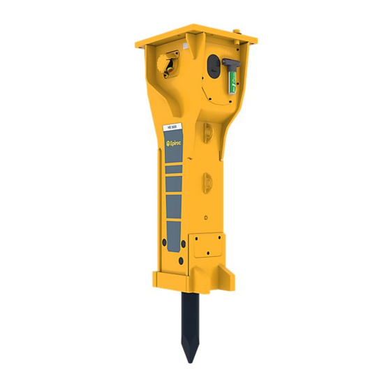
Safety and operating instructions The working tool is retained in the lower breaker 3 Overview part. K. The percussion piston is guided in the cylinder. Pressure line »P« 3.1 Equipment description M. Non-return valve of percussion compartment venti- The illustration gives an overview of the main parts and lation components of the hydraulic attachment. -
Page 17: Signs / Labels
Safety and operating instructions 3.3.2 Labels 3.3 Signs / labels Sound Power WARNING Missing warnings The label states the guaranteed The name plate and the labels on the hydraulic attach- sound power level in accordance ment contain important information about the hydraulic with EC directive 2000/14/EC. -
Page 18: Applications
Heavily reinforced con- crete, demolition of power n Check the delivery for visual damage. stations and bridges n If any defects are found, consult the Epiroc Customer Rock mining / breaking Primary breaking Center / dealer in your area. Secondary breaking,... -
Page 19: Transport
Safety and operating instructions 4 Transport WARNING Hoist tipping over / hydraulic attach- ment falling The hydraulic attachment is heavy. The hoist/lifting equipment and/or hydraulic attachment tipping over or falling may cause serious injury and material damage. u Only transport the hydraulic attachment with lifting ●... -
Page 20: Transport Using A Crane
Safety and operating instructions 4.1 Transport using a crane 4.2 Transport using a forklift truck n Secure the hydraulic attachment with ropes or chains as shown in the following illustration. WARNING Hydraulic attachment tipping over The hydraulic attachment tipping off the fork of the forklift truck or the pallet may cause serious injury. -
Page 21: Transport Using A Truck
Safety and operating instructions 4.3 Transport using a truck WARNING Hydraulic attachment tipping over / slipping The hydraulic attachment slipping or tipping over and falling from the loading area of a lorry may cause serious injury. u Place the hydraulic attachment on a pallet. u Strap the hydraulic attachment to the pallet using suitable strapping (see illustration in chapter Trans- port using a forklift truck). -
Page 22: Installation
Dispose of it in accordance with the applicable envi- Our hydraulic attachments are basically designed for use ronmental regulations. with mineral oils. Consult the Epiroc Customer Center / Dealer in your area before using other hydraulic oils ap- 5.1 Media/consumables proved by the carrier manufacturer. -
Page 23: Manufacturing The Adapter Plate
Safety and operating instructions 5.2 Manufacturing the adapter WARNING Hands and fingers being cut off or hurt Bores and surfaces can act like a pair of scissors and plate cut off or hurt parts of your body. Construction Tools GmbH also supplies base plates to u Never use your fingers to check bores or fitting sur- manufacture adapter plates alternatively to the adapter faces. -
Page 24: Attaching The Hydraulic Attachment To The Carrier
The adapter plate must not be stopped by mechanical cut off or hurt parts of your body. stops in either position. Consult the Epiroc Customer u Never use your fingers to check bores or fitting sur- Center/Dealer in your area if the adapter plate is stopped faces. - Page 25 Safety and operating instructions NOTICE Total damage to the hydraulic attachment WARNING Components bursting Polluted hydraulic lines and connections may enable Components of the swivel joint may burst. Metal parts sand, fragments of material and dirt to penetrate the hy- may become projectiles and cause serious injuries and draulic attachment and damage it completely.
-
Page 26: Removing The Hydraulic Attachment From The Carrier
Safety and operating instructions WARNING Hot parts The percussion unit, the working tool, hoses, pipes and fittings become very hot during operation. Touching them may lead to burns. u Never touch hot parts. u If you have to carry out activities where you have to touch the parts, wait for them to cool down first. -
Page 27: Dustprotector
Safety and operating instructions n Lift the adapter plate with a suitable lifting equipment n Remove the guide ring (F), floating ring (E) and and put it down on timber support blocks. counter ring (D) of the DustProtector system. n Lock the elastic pad with the transport safety device. n Remove the wiper (A). -
Page 28: Working Tool
Safety and operating instructions 5.8.1 Selecting the right working tool 5.8 Working tool The standard available working tools are shown. The dif- WARNING Unexpected movement ferent cutter geometries may influence the production re- Sudden movements of the carrier may cause serious in- sult, depending on the actual use. -
Page 29: Installation
Safety and operating instructions n Remove the screws (Z), washers (Y), plate (X), and 5.8.2 Installation plugs (E). n Place the hydraulic breaker on timber support blocks. n Use a pin punch and a hammer to drive the bolt (G) NOTICE The working tool may break for the retainer bars (D) out of the lower breaker part (F) from the side. -
Page 30: Removal
Safety and operating instructions 5.8.3 Removal n Place the hydraulic breaker on timber support blocks. WARNING The working tool suddenly comes loose A clamped working tool is still under the pressure of the piston accumulator. When the working tool is loosened, it will partly jump out of the hydraulic breaker;... -
Page 31: Operation
Safety and operating instructions NOTICE Damage due to idling strokes 6 Operation If the percussion piston carries out a hammer action WARNING Components bursting without hitting the working tool, it is carrying out an idling stroke. If this happens it will lead to hydraulic peak pres- Components of the swivel joint may burst. -
Page 32: Preparations Before Starting
/ or the the hydraulic attachment may be flung away and can Epiroc Customer Center / Dealer in your area. cause serious injury if people are hit by them. Small ob- jects falling from a great height can also cause serious n Switch the hydraulic attachment on and off, as de- damage. -
Page 33: Correct Operation
Safety and operating instructions Larger swing angles would lead to bending loads and 6.5 Correct operation damage to the working tool and the hydraulic breaker. 6.5.1 Working angle n Always position the tool so that it hits the material to 6.5.2 Advance be broken at a right angle. -
Page 34: High Ambient Temperature
Safety and operating instructions The temperature of the hydraulic oil of the carrier must 6.5.4 High ambient temperature be at least 0 °C (32 °F). n Only use hydraulic oils of sufficient viscosity. n Start the hydraulic attachment when the temperature In summer and in tropical climates, the minimum re- has risen to 0 °C (32 °F). -
Page 35: Prohibited Operation
Safety and operating instructions 6.6.3 Moving objects 6.6 Prohibited operation n Never use the hydraulic attachment to move debris. This would damage the hydraulic attachment. 6.6.1 Lifting/Transporting WARNING Falling load The lifted object can fall and cause serious injuries or death. -
Page 36: Blank Firing Of The Working Tool
Safety and operating instructions 6.6.5 Blank firing of the working tool 6.6.6 Cylinder end positions The working tool "blank fires" if the percussion energy is n Avoid operating the hydraulic attachment when the transferred to the retainer bars instead of to the material carrier stick and bucket cylinder is in one of its end to be broken. -
Page 37: Working With Safety Equipment
If the situation requires a n Before using the hydraulic breaker in or under water, high single blow energy, the system produces a full consult the Epiroc Customer Center / Dealer in your stroke and a high single blow energy. area. -
Page 38: Poweradapt
Safety and operating instructions 6.10 PowerAdapt PowerAdapt protects the hydraulic breaker against hy- draulic overloads and switches it off if the hydraulic input energy is too high. An overload occurs when the hydraulic breaker is oper- ated while the delivery rate and the pressure from the carrier are too high. -
Page 39: Maintenance
Safety and operating instructions 7 Maintenance WARNING Unexpected movement Sudden movements of the carrier may cause serious in- The maintenance activities are carried out by the carrier jury. driver. u Secure the carrier such that it cannot move unex- pectedly. WARNING Hot hydraulic oil squirting out u Observe the carrier manufacturer’s instructions. -
Page 40: Maintenance Schedule
Safety and operating instructions 7.1 Maintenance schedule ® during a shift Monitor the filling level of the grease cartridge of the ContiLube II lubrication sys- tem and immediately replace an empty cartridge. Monitor the lubricant film on the shaft of the working tool. Manual lubrication of the working tool approx. -
Page 41: Depressurising The Hydraulic System
Safety and operating instructions Case 2: If no facility for measuring the pressure is 7.2 Depressurising the hydraulic present in the supply pipe to the hydraulic breaker and system the return pipe is connected to the tank without an inter- mediate valve connection, you must observe the follow- Even when you have switched off the carrier, a consider- ing steps in order to depressurise the hydraulic breaker:... -
Page 42: Cleaning
Safety and operating instructions the shut-off valves or disconnect the quick-release 7.4 Lubrication couplings, so that no hydraulic oil can flow back from the carrier. 7.4.1 Checking the lubricant film The lubricant film on the shaft of the working tool must 7.3 Cleaning be checked during the work shift. -
Page 43: Automatic Lubrication
If you have questions how to use the ContiLube ® II, sealed, otherwise no grease supply will be possible. contact the Epiroc Customer Center / dealer in your • You can change the supply volume by adjusting the area. metering screw (A), depending on the actual use. -
Page 44: Manual Lubrication
3363 0946 69 Filling device for use with 45-kg containers: part number 3363 0664 11 For further information, please contact the Epiroc Cus- tomer Center / Dealer in your area. • Lubrication interval: approx. every 2 hours • Hydraulic breaker without DustProtector: 5 to 15 strokes from the manual grease gun •... -
Page 45: Checking The Tensioning Bolts
Have broken tensioning bolts immediately replaced. n If you have any questions about replacement of bro- ken tensioning bolts, consult the Epiroc Customer Center / Dealer in your area. You can only check the front tensioning bolts, if you dis- mount the adapter plate and the elastic pad (see chapter Removing the adapter plate). -
Page 46: Checking The Retainer Bars
Do not use the hydraulic breaker again if you have found the surface to be chipped or cracked. n Consult the Epiroc Customer Center / Dealer in your area. n Replace the working tool if the shaft has worn to the minimum diameter D stated below. -
Page 47: Checking The Wear Bushes And Impact Ring
Clean the area around the impact ring to enable a visual check. The lower wear bush can be replaced on site. Consult the Epiroc Customer Center / Dealer in your area. n Remove all remnants of lubricant from the inside of the lower breaker part before installing new parts. -
Page 48: Checking And Cleaning The Dustprotector System
Safety and operating instructions n Remove the floating ring (E), counter ring (D) and 7.10 Checking and cleaning the guide ring (F) (see chapter DustProtector/Re- DustProtector system moval). An important factor for the DustProtector operation is n Clean the space in front of the flexible wiper (A) of all that the floating ring which moves in a radial direction loose dust. -
Page 49: Piston Accumulator
Safety and operating instructions HB 4100, HB 4100 DP 7.11 Piston accumulator The pressure in the piston accumulator is measured at the filling valve (G). The piston accumulator is also filled through this valve. HB 3100, HB 3100 DP The following accessories can be supplied: 1 nitrogen filling device 1 test pressure gauge ¼", 0-25 bar, test category 1.6 1 nitrogen bottle HB 3600, HB 3600 DP... -
Page 50: Checking The Pressure In The Piston Accumulator
Safety and operating instructions 7.11.1 Checking the pressure in the piston 7.11.2 Release the pressure from the accumulator piston accumulator Check the gas pressure in the piston accumulator n Release gas from the piston accumulator to depres- monthly, and in cases of decreasing power or failure of surise the piston accumulator or if the value mea- the hydraulic breaker. -
Page 51: Hp-Accumulator
Slowly open the pressure relief valve (D) to let the ni- trogen flow into the piston accumulator. Contact the Epiroc Customer Center / Dealer in your area for a professional. n Read out the pressure increase from the pressure gauge (B). -
Page 52: Checking The Fastening Screws
4. Connect the pressure gauge to the HP-accumulator via the pressure line »P«. The HP-accumulator can be replaced on site. Contact the Epiroc Customer Center / Dealer in your area. 5. Close the tank line »T«. You need an assistant to monitor the pressure 7.12.2 Checking the fastening screws... -
Page 53: Checking The Hydraulic Lines
The wear rails (A) in the lower section of the breaker 7.14 Checking and cleaning the box can be replaced as required. Please consult the Epiroc Customer Center / dealer in your area. hydraulic oil filter An oil filter must be integrated in the tank line of the hy- draulic system. -
Page 54: Bolt Connections / Tightening Torques
Safety and operating instructions 7.17 Bolt connections / Tightening torques The bolt connections of hydraulic breakers are subjected to very high loads. Tighten any loose connections without exceeding the recommended tightening torques. HB 3100 HB 3600 HB 4100 HB 4700 HB 3100 DP HB 3600 DP HB 4100 DP HB 4700 DP Connection point Interval Type of... - Page 55 Safety and operating instructions Apply anti-seize compound to the Allen screw threads before inserting them. The contact faces of the screw head and the lock washers must not be lubricated. **HB 3100 1. Pre-tighten the tensioning bolts to 500 Nm (369 ft lbs) crosswise, **HB 4100 2.
- Page 56 Safety and operating instructions Actual details may differ. © Construction Tools GmbH | 3390 5203 01 | 2019-08-06 Original Instructions...
-
Page 57: Troubleshooting
Replace the magnet Workshop Operating pressure too low Check the carrier engine speed, the Carrier driver or Epiroc Customer pump delivery and the pressure relief Center / Dealer in your area valve; check the operating pressure Adjust settings and replace defective... -
Page 58: Impact Force Too Low
(see chapter Technical specifications) Return pressure too high Check and lower the return pressure Epiroc Customer Center / Dealer in your area Hydraulic oil return to the tank via a Connect the hydraulic oil return circuit Carrier driver or Epiroc Customer... -
Page 59: Oil Leaks From Ports "P" Und "T
Safety and operating instructions Cause Remedy O-rings defective Replace O-rings Workshop 8.5 Oil leaks from ports »P« und »T« Cause Remedy Cap nuts loose Check the cap nuts and tighten (see Carrier driver chapter Bolt connections/Tighten- ing torques) Hose connection CL to port »P« for Check the cap nuts and tighten Carrier driver ®... -
Page 60: Oil Or Grease Escapes From The Contilube® Ii
Check carrier settings and adjust Epiroc Customer Center / Dealer in your area Operation in high outside temperature Check oil temperature and install an Workshop or Epiroc Customer Cen-... -
Page 61: Repair
Construction Tools GmbH. These professionals must follow all safety instructions and guidelines for repair. n For technical support contact the Epiroc Customer Center / Dealer in your area. 9.1 Sending in the hydraulic attachment for repairs... -
Page 62: Storage
Safety and operating instructions NOTICE Environmental damage due to hydraulic oil 10 Storage Hydraulic oil is environmentally harmful and must not WARNING Hydraulic breaker / working tool fall penetrate the ground or enter the water table or water supplies. The hydraulic breaker and the working tool are heavy. If u Collect any hydraulic oil which escapes. -
Page 63: Working Tool
Safety and operating instructions n Contact the Epiroc Customer Center / Dealer in your area. n Professionals trained by Construction Tools GmbH will disassemble the hydraulic breaker properly and: – check any parts liable to corrosion (percussion piston, cylinder, control) for corrosion damage. -
Page 64: Disposal
Clean the hydraulic breaker (see chapter Cleaning). n Before disposal the HP-accumulator must be depres- surised. This must be done by an authorized person. Contact the Epiroc Customer Center / dealer in your area. n Dispose of the hydraulic breaker in line with all appli- cable regulations or consult an authorised and spe- cialised recycling company. -
Page 65: Technical Specifications
32 mm (1.3 in.) Start up mode Weights apply to standard carriers only. Any variances must be agreed with Epiroc and/or the carrier manufacturer prior to attachment Hydraulic breaker incl. breaker box, working tool and adapter plate of medium size. Please note that the service weight can be considerably higher, depending on the adapter plate. - Page 66 32 mm (1.3 in.) Start up mode Weights apply to standard carriers only. Any variances must be agreed with Epiroc and/or the carrier manufacturer prior to attachment Hydraulic breaker incl. breaker box, working tool and adapter plate of medium size. Please note that the service weight can be considerably higher, depending on the adapter plate.
-
Page 67: Noise Declaration Statement
Safety and operating instructions 12.1 Noise declaration statement HB 3100 HB 3600 HB 4100 HB 4700 HB 3100 DP HB 3600 DP HB 4100 DP HB 4700 DP Sound pressure dB(A) Sound power dB(A) Sound pressure level according to EN ISO 3744 in accordance with directive 2000/14/EC at 10 metres distance. Guaranteed sound power according to EN ISO 3744 in accordance with directive 2000/14/EC inclusive spread in pro- duction. -
Page 68: Ec Declaration Of Conformity (Ec Directive 2006/42/Ec)
Safety and operating instructions 13 EC Declaration of Conformity (EC Directive 2006/42/EC) We, Construction Tools GmbH, hereby declare that the machines listed below conform to the provisions of EC Directive 2006/42/EC (Machinery Directive) and 2000/14/EC, ANNEX V (Noise Directive) and 2014/68/EU (Pressure Equipment Directive), and the harmonised standards mentioned below. - Page 72 Any unauthorized use or copying of the contents or any part thereof is prohibited. This applies in particular to trademarks, model denominations, part numbers, and drawings. epiroc.com...
Need help?
Do you have a question about the HB Series and is the answer not in the manual?
Questions and answers