Xerox Phaser 6500 Service Manual
Color laser printer/multi-function printer
Hide thumbs
Also See for Phaser 6500:
- User manual (162 pages) ,
- Quick use manual (5 pages) ,
- Brochure & specs (4 pages)

Related Manuals for Xerox Phaser 6500


Summary of Contents for Xerox Phaser 6500
- Page 1 Phaser 6500/WorkCentre 6505 ® ® Color Laser Printer/Multi-Function Printer Phaser 6500/ ® WorkCentre 6505 ® Service Manual Xerox Internal-Use Only...
- Page 2 The following servicing instructions are for use by qualified service personnel only. To avoid personal injury, do not perform any servicing other than that contained in the operating instructions, unless you are qualified to do so. First Printing: February 2011 Xerox Internal Use Only...
-
Page 3: Table Of Contents
Phaser 6500/WorkCentre 6505 Operational Overview ........ - Page 4 Fax Standards (ITU-T Recommendations)............2-73 Xerox Internal Use Only Phaser 6500/WorkCentre 6505 Service Manual http://www.manuals4you.com...
- Page 5 Buffer Over..................3-77 Phaser 6500/WorkCentre 6505 Service Manual...
- Page 6 Bus#0-Device# (0/1)..............3-162 Xerox Internal Use Only Phaser 6500/WorkCentre 6505 Service Manual http://www.manuals4you.com...
- Page 7 Macintosh Troubleshooting ..............4-82 Phaser 6500/WorkCentre 6505 Service Manual...
- Page 8 Guaranteed Print Areas ............... .5-56 viii Xerox Internal Use Only Phaser 6500/WorkCentre 6505 Service Manual http://www.manuals4you.com...
- Page 9 SFP Cassette Stopper ................8-32 Phaser 6500/WorkCentre 6505 Service Manual...
- Page 10 Feed Drive Assembly ............... . . 8-117 Xerox Internal Use Only Phaser 6500/WorkCentre 6505 Service Manual http://www.manuals4you.com...
- Page 11 Option Separator Holder ..............8-190 Phaser 6500/WorkCentre 6505 Service Manual...
- Page 12 Service Kits ..................9-62 Xerox Internal Use Only Phaser 6500/WorkCentre 6505 Service Manual http://www.manuals4you.com...
- Page 13 MFP Duplex Unit ................10-51 Phaser 6500/WorkCentre 6505 Service Manual...
- Page 14 Acronyms and Abbreviations ................A-18 Index Xerox Internal Use Only Phaser 6500/WorkCentre 6505 Service Manual http://www.manuals4you.com...
-
Page 15: About This Service Manual
About this Service Manual The Phaser 6500/WorkCentre 6505 Service Manual is the primary document used for repairing, maintaining, and troubleshooting the printer. Use this manual as your primary resource for understanding the operational characteristics of the printer and all available options. This manual describes specifications, theory, and the diagnosis and repair of problems occurring in the printer and attached options. -
Page 16: Manual Organization
Manual Organization The Phaser 6500/WorkCentre 6505 Service Manual contains these sections: Introductory, Safety, and Regulatory Information: This section contains important safety information and regulatory requirements. Chapter 1 - General Information: This section contains an overview of the printer’s operation, configuration, specifications, and consumables. -
Page 17: Symbols Marked On The Product
A personal injury hazard exists that may not be apparent. For example, a panel may cover the hazardous area. Danger: A personal injury hazard exists in the area where you see the sign. Phaser 6500/WorkCentre 6505 Service Manual Xerox Internal Use Only xvii... -
Page 18: Power Safety Precautions
• if the printer is dropped or damaged, • if you suspect that the product needs servicing or repair, • whenever you clean the product. xviii Xerox Internal Use Only Phaser 6500/WorkCentre 6505 Service Manual http://www.manuals4you.com... -
Page 19: Electrostatic Discharge (Esd) Precautions
Handle ICs and Erasable Programmable Read-Only Memories (EPROM’s) carefully to avoid bending pins. • Pay attention to the direction of parts when mounting or inserting them on Printed Circuit Boards (PCB’s). Phaser 6500/WorkCentre 6505 Service Manual Xerox Internal Use Only... -
Page 20: Service Safety Summary
Class 1 Laser Product The Phaser 6500/WorkCentre 6505 is certified to comply with Laser Product Performance Standards set by the U.S. Department of Health and Human Services as a Class 1 Laser Product. This means that this product does not emit hazardous laser radiation;... - Page 21 This printer uses heat to fuse the image on the media. When operating, the Fuser is very hot. Turn the printer power Off and allow the Fuser to cool before servicing the Fuser or adjacent components. Phaser 6500/WorkCentre 6505 Service Manual Xerox Internal Use Only...
-
Page 22: Regulatory
• Consult the dealer or an experienced radio/television technician for help. Any changes or modifications not expressly approved by Xerox could void the user's authority to operate the equipment. To ensure compliance with Part 15 of the FCC rules, use shielded interface cables. - Page 23 European Union The CE mark applied to this product symbolizes Xerox’s declaration of conformity with the following applicable Directives of the European Union as of the dates indicated: December 12, 2006: Low Voltage Directive 2006/95/EC December 15, 2004: Electromagnetic Compatibility Directive 2004/108/EC March 9, 1999 - Radio &...
- Page 24 Xerox Internal Use Only Phaser 6500/WorkCentre 6505 Service Manual http://www.manuals4you.com...
-
Page 25: General Information
General Information In this chapter... • Printer Introduction and Overview • Printer Configuration • Parts of the Printer • Printer Options • Maintenance Items • Consumables • Specifications Chapter... -
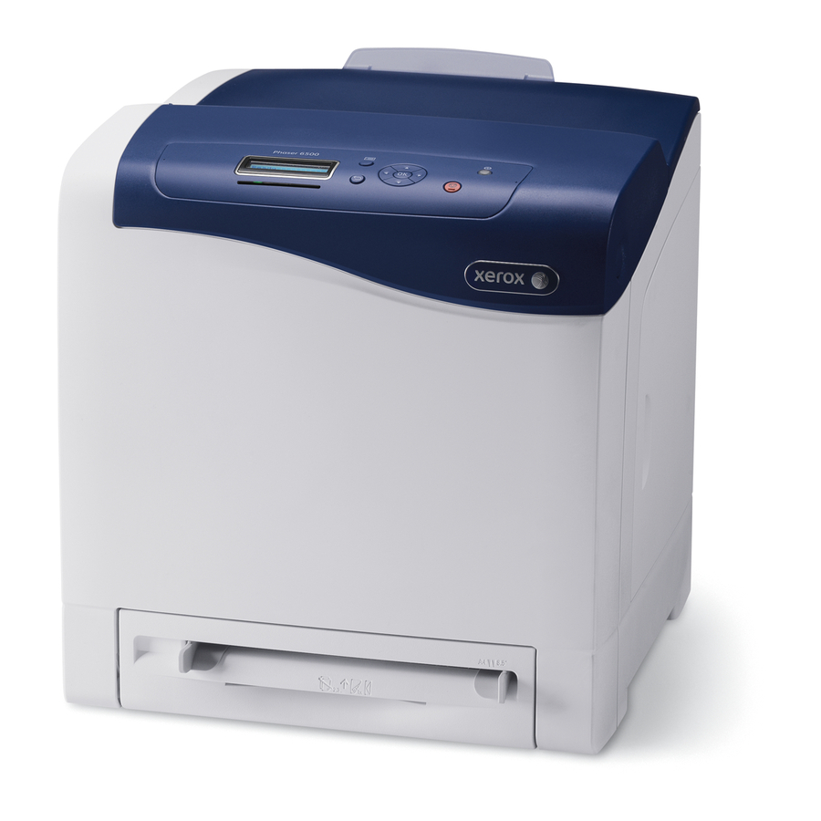
Page 26: Printer Introduction And Overview
PostScript 3 and PCL6 page description languages The printer supports USB 2.0, 10/100/1000 Base-TX, and IPv6 Ethernet connectivity. The Phaser 6500 is a single-function printer (SFP) that provides a 250-sheet Tray and a Manual Feed slot supporting single-sheet feed of specialty media, card stock, and envelopes. -
Page 27: Printer Configuration
General Information Printer Configuration The tables list Phaser 6500/WorkCentre 6505 printer configuration Single-Function Printer (SFP) Configuration Features Phaser 6500 Processor Speed 400 MHz 256 MB Memory Configuration Print Speed (Color/Mono A-size) 24/24 Resolutions (dpi) Standard 600 x 600 x 1 bit... -
Page 28: Parts Of The Printer
Media tray (Tray 1 if optional 250-sheet feeder is installed). Manual Feed slot Front Cover Control Panel Output tray Button for opening the Front Cover and releasing the Duplex Unit. Toner Cartridges Toner Door Xerox Internal Use Only Phaser 6500/WorkCentre 6505 Service Manual http://www.manuals4you.com... -
Page 29: Mfp Front And Side Views
Button for opening the Front Cover and releasing the Duplex Unit. Power switch Toner Door Manual Feed slot Media tray (Tray 1 if optional 250-sheet feeder is installed). Front Cover Control Panel USB Port (Type A) Phaser 6500/WorkCentre 6505 Service Manual Xerox Internal Use Only... -
Page 30: Sfp Rear View
General Information SFP Rear View s6500-002 Power switch Power cord connector USB port Network connector Optional memory slot Xerox Internal Use Only Phaser 6500/WorkCentre 6505 Service Manual http://www.manuals4you.com... -
Page 31: Mfp Rear View
General Information MFP Rear View s6505-004 ADF Cover IP Board Cover USB Port (Type B) Network connector Phone Line out Phone Line in AC Inlet Phaser 6500/WorkCentre 6505 Service Manual Xerox Internal Use Only... -
Page 32: Internal View, Sfp
General Information Internal View, SFP s6500-005 Fuser Imaging Unit Front Cover and Duplex Unit release. Duplex Unit Transfer Belt (Tray 1 removed so the Transfer Belt folds down completely). Xerox Internal Use Only Phaser 6500/WorkCentre 6505 Service Manual http://www.manuals4you.com... -
Page 33: Internal View, Mfp
General Information Internal View, MFP s6500-007 Front Cover and Duplex Unit release Transfer Belt Imaging Unit Fuser Document Glass Toner Cartridges Duplex Unit Phaser 6500/WorkCentre 6505 Service Manual Xerox Internal Use Only... -
Page 34: Control Panel
Blinks when an error occurs that cannot be ■ resolved by the user. Off when the printer is in Energy Saver mode. ■ 1-10 Xerox Internal Use Only Phaser 6500/WorkCentre 6505 Service Manual http://www.manuals4you.com... - Page 35 Press to switch between Color and Black and White modes for your copy, Fax, and scan jobs. Black and White/Color Upper light indicates Black and White mode. Lower indicator lights light indicates Color mode. Phaser 6500/WorkCentre 6505 Service Manual Xerox Internal Use Only 1-11...
-
Page 36: Printer Options
The printer features one slot for optional memory that supports 256 MB, 512 MB, 1024 MB DDR2 DIMMs, to a maximum of 1280 MB (256 MB standard + 1024 MB optional). Xerox offers only 512 MB memory modules. Memory modules must meet the following characteristics: •... -
Page 37: Optional Feeder
The only difference is the size, caused by the larger footprint of the MFP. Note Remove the protective cap from the Optional Feeder connector before installation. Connector s6500-510 Connector s6505-510 Phaser 6500/WorkCentre 6505 Service Manual Xerox Internal Use Only 1-13... -
Page 38: Duplex Unit
Electrical connection to the printer is made by a single interface connector Note When installing the Duplex Unit for the first time, be sure to remove the protective cap from the connector inside the Front Cover. s6500-012 1-14 Xerox Internal Use Only Phaser 6500/WorkCentre 6505 Service Manual http://www.manuals4you.com... -
Page 39: Maintenance Items
Routine maintenance items are parts or assemblies that require periodic replacement. These items are typically customer replaceable (CRU). ADF Feed Roller Assembly ADF Separator Pad Fuser Assembly Assembly Imaging Unit Separator Roller Feed Roller Toner Cartridges s6500-013 Phaser 6500/WorkCentre 6505 Service Manual Xerox Internal Use Only 1-15... -
Page 40: Consumables
— High Capacity 2,500 pages 3,000 pages Note Starter capacity cartridges are packaged with the printer when shipped from the factory. These starter cartridges are not available for order. 1-16 Xerox Internal Use Only Phaser 6500/WorkCentre 6505 Service Manual http://www.manuals4you.com... -
Page 41: Specifications
Less than 30 seconds from Power On Operating System Windows 2003/2008 Server/ XP/ Vista/ Windows7 Macintosh OS 10.5 and greater Linux Redhat and SuSe * Assumes a 30 day month of printing. Phaser 6500/WorkCentre 6505 Service Manual Xerox Internal Use Only 1-17... -
Page 42: Scanning Specifications
Off, Normal, Higher (1, 2) Scan to Desktop via Up to 6 SMB servers Scan to FTP Up to 6 FTP servers Scan to E-mail Yes (no individual user log in) 1-18 Xerox Internal Use Only Phaser 6500/WorkCentre 6505 Service Manual http://www.manuals4you.com... -
Page 43: Copy Specifications
Multiple Up (N to 1) Off, Auto, ID Copy, Manual Duplex Copy On, Off Poster 2x2, 3x3, 4x4 Auto Fit On, Off Cloning On, Off Collate (max pages) Color: 50 ■ B/W: 50 ■ Phaser 6500/WorkCentre 6505 Service Manual Xerox Internal Use Only 1-19... -
Page 44: Fax Specifications
PCL driver - supported PS driver - not support Color Not supported Delayed Start Up to 24 hours Broadcast Sending Up to 30 destinations Zoom 25%-400% (same as printer driver) 1-20 Xerox Internal Use Only Phaser 6500/WorkCentre 6505 Service Manual http://www.manuals4you.com... -
Page 45: Memory Specifications
Power Consumption (with all options, 110 or 220 V) Power Saver Mode 5 W or less Standby Mode (Fuser On) 50W or less Color Continuous Printing 280W or less B/W Continuous Printing 280W or less Phaser 6500/WorkCentre 6505 Service Manual Xerox Internal Use Only 1-21... -
Page 46: Print Speed
15 to 85% RH Standby 5 to 85% RH Altitude Operating 0 to 3,100 meters (10,171 feet) Acoustic Noise LWA(B) Sound Power Level (B) Sound Pressure (dBA) Printing 6.46 51.6 Standby 25.7 1-22 Xerox Internal Use Only Phaser 6500/WorkCentre 6505 Service Manual http://www.manuals4you.com... -
Page 47: Operating Mode
LED: If printer is online, Ready LED is On. Power Saver The printer enters Power Saver mode Mode (Deep when it has not received print data for the Sleep) specified time. Exposure The system is at Pause. Phaser 6500/WorkCentre 6505 Service Manual Xerox Internal Use Only 1-23... -
Page 48: First Print Output Time
FPOT is 12 seconds. If the last job had any single color page, and the first page in the next job is color, FPOT is 13 seconds. If the printer has to switch modes, FPOT is 18 seconds. 1-24 Xerox Internal Use Only Phaser 6500/WorkCentre 6505 Service Manual http://www.manuals4you.com... -
Page 49: First Copy Output Time
584 mm (23”) Height with 250-Sheet Feeder 690 mm (27.1 in.) Width 430 mm (16.9 in.) Depth 544 mm (21.4 in.) Weight (base printer with consumables) 28.8 kg (63.5 lb.) Phaser 6500/WorkCentre 6505 Service Manual Xerox Internal Use Only 1-25... - Page 50 60.7cm 77.5 mm (23.9 in.) (30.51 in.) 32 cm 12.6 in. 905 cm 35.62 in. 10 cm (3.94 in.) 25 cm 60 cm (9.84 in.) (23.6 in.) s6500-015 1-26 Xerox Internal Use Only Phaser 6500/WorkCentre 6505 Service Manual http://www.manuals4you.com...
-
Page 51: Mounting Surface Specifications
• Color-to-Color mis-registration, primarily in the horizontal (laser scan) direction. • A smear or line of toner approximately 40 mm from the trailing edge of the print. Phaser 6500/WorkCentre 6505 Service Manual Xerox Internal Use Only 1-27... -
Page 52: Media And Tray Specifications
A4 (210 x 297 mm) ■ A5 (148 x 210 mm) ■ JIS B5 (182 x 257 mm) ■ Custom size range: ■ Width: 5.8–8.5 in. (147.3–215.9 mm) Height: 8.3–14 in. (210.8–355.6 mm) 1-28 Xerox Internal Use Only Phaser 6500/WorkCentre 6505 Service Manual http://www.manuals4you.com... - Page 53 Height: 5–14 in. (127–355.6 mm) Paper Type and Plain (60–105 g/m2, 16–28 lb. Bond) ■ Weight Letterhead (plain) ■ Hole Punched (plain) ■ Colored paper (plain) ■ Loading Capacity One sheet at a time Phaser 6500/WorkCentre 6505 Service Manual Xerox Internal Use Only 1-29...
- Page 54 Original Size Width: 4.1–8.5 in. (148–216 mm) ■ Length: 8.3–14 in. (210–355.6 mm) ■ Weight Range 50–125 g/m (17–32 lb. Bond) ■ Loading Capacity To MAX fill line wc6505_007 1-30 Xerox Internal Use Only Phaser 6500/WorkCentre 6505 Service Manual http://www.manuals4you.com...
-
Page 55: Theory Of Operation
Theory of Operation In this chapter... • Phaser 6500/WorkCentre 6505 Operational Overview • Print Process • Media Path • Sensors • Major Assemblies and Functions • Operation Modes • Printer Control • Drive • Scanner • Automatic Document Feeder •... -
Page 56: Phaser 6500/Workcentre 6505 Operational Overview
Theory of Operation Phaser 6500/WorkCentre 6505 Operational Overview The Phaser 6500 is a full-color printer and the WorkCentre 6505 is a full-color multifunction printer, both using raster output scanner (ROS) lasers with an electrophotographic four-color CMYK process. The tandem system consists of four color drums (C, M, Y, and K) which creates the toner image. - Page 57 Theory of Operation Imaging Unit : Laser Beam [(1) Charge] : Media Path [(3) Development] Laser Unit [(4) Transfer] Fuser [(2) Exposure] [(5) Cleaning] [(6) Fusing] Transfer Belt [(4) Transfer] [(7) Cleaning] s6500-019 Phaser 6500/WorkCentre 6505 Service Manual Xerox Internal Use Only...
-
Page 58: Charging
The cleaning roller is a sponge that contacts the BCR to catch the toner. Photoreceptor Conductor Cleaning Roller Drum HVPS s6500-020 Xerox Internal Use Only Phaser 6500/WorkCentre 6505 Service Manual http://www.manuals4you.com... -
Page 59: Exposure
The area on the drum where the laser beam strikes becomes conductive. The negative charge on the surface flows to the more positive drum, lowering the voltage potential. Phaser 6500/WorkCentre 6505 Service Manual Xerox Internal Use Only... - Page 60 Positive Electric Charge Photoreceptor Conductor Laser Beams Drum Surface Drum Laser Beam Electrostatic Latent Image Concept of Drum Electrostatic Potential on Laser Beam Latent Image Drum Surface Laser Beam Photoreceptor Conductor s6500-022 Xerox Internal Use Only Phaser 6500/WorkCentre 6505 Service Manual http://www.manuals4you.com...
-
Page 61: Development
Once the toner is deposited on the drum, the potential and the toner-attracting force of the corresponding portion decreases because the increase of negative charge lowers the potential at that portion. Phaser 6500/WorkCentre 6505 Service Manual Xerox Internal Use Only... -
Page 62: Toner Dispense Path
Cartridge shutter moves forward opening the toner supply port. The toner is fed to the Imaging Unit from a second port in the auger housing. Toner Cartridge Shutter Auger Toner Motor s6500-025 Xerox Internal Use Only Phaser 6500/WorkCentre 6505 Service Manual http://www.manuals4you.com... -
Page 63: Image Transfer
Y, M, C, and K order. Paper : Negative electric charge : Positive electric charge : Toner Drum (K) Drum (C) Drum Surface Drum (M) Drum (Y) HVPS Transfer Belt s6500-026 Phaser 6500/WorkCentre 6505 Service Manual Xerox Internal Use Only... - Page 64 After the negative charged toner image on the drum surface is drawn by the positive charge on the belt, it is transferred from the drum to the paper. The Transfer Belt feeds the paper toward the Fuser. 2-10 Xerox Internal Use Only Phaser 6500/WorkCentre 6505 Service Manual http://www.manuals4you.com...
-
Page 65: Imaging Unit
Erase Lamp to prepare the drum for the next exposure cycle. Erase Lamp : Positive Electric Charge : Negative Electric Charge : Toner Blade Conductor Photoreceptor Drum Cleaning Roll s6500-028 Phaser 6500/WorkCentre 6505 Service Manual Xerox Internal Use Only 2-11... -
Page 66: Excess Toner Collection
Toner Cartridge. The waste toner is not reused, but is discarded along with the cartridge when the cartridge is empty. Auger Cleaning Side Collection Box Toner Cartridge Auger Cleaner Blade s6500-029 2-12 Xerox Internal Use Only Phaser 6500/WorkCentre 6505 Service Manual http://www.manuals4you.com... -
Page 67: Fusing
The Transfer Belt is cleaned by a cleaning blade that removes excess toner from the Transfer Belt surface and directs waste toner to a reservoir. Blade Assy Cleaner Box Belt s6500-031 Phaser 6500/WorkCentre 6505 Service Manual Xerox Internal Use Only 2-13... -
Page 68: Media Path
Drive Motor / Heat Roller / Pressure Belt Exit Roller in the Fuser Drive Motor / Clutch / Exit Roller Duplex Unit Output Tray Drive Motor / Duplex Roller s6500-032 2-14 Xerox Internal Use Only Phaser 6500/WorkCentre 6505 Service Manual http://www.manuals4you.com... -
Page 69: Media Path Components
No Paper Sensor Manual Feed No Paper Sensor Registration Sensor Separator Roller Turn Roller(Metal) Tray 2 No Paper Sensor Turn Roller (Rubber) Separator Roller Feed Roller Paper Path Sensor s6500-033 Phaser 6500/WorkCentre 6505 Service Manual Xerox Internal Use Only 2-15... -
Page 70: Adf Media Path
Exit Roll that rotates by the torque from the ADF Motor. : Paper Transfer : Paper Sensors Feed Roller Nudger Roller Takeaway Roller Exit Roller Feed Sensor Document Sensor ADF Separator Pad Home Position (CVT Position) s6500-471 2-16 Xerox Internal Use Only Phaser 6500/WorkCentre 6505 Service Manual http://www.manuals4you.com... -
Page 71: Sensors
When the sensing area is vacant, nothing is between the arms of the sensor, light falls on the photo-receptor sending the signal High. If the light is interrupted, the photo-transistor goes Low. Actuator Optic_Sensor_Actuator Phaser 6500/WorkCentre 6505 Service Manual Xerox Internal Use Only 2-17... - Page 72 Actuator Button Blade Contact Interlock_Switch Thermistors Thermistors have a known value of resistance whose value varies with temperature. Used primarily in the Fuser for temperature sensing. 2-18 Xerox Internal Use Only Phaser 6500/WorkCentre 6505 Service Manual http://www.manuals4you.com...
-
Page 73: Sensors In The Media Path
Sensors in the Automatic Document Feeder This drawing shows the location of sensors in the Automatic Document Feeder on the WorkCentre 6505. Feed Sensor ADF Motor Cover Open Sensor ADF Board Document Sensor s6500-081 Phaser 6500/WorkCentre 6505 Service Manual Xerox Internal Use Only 2-19... -
Page 74: Major Assemblies And Functions
The side guides move at a right angle to the paper transfer direction to align the paper width. • Tray End Guide The end guide moves in toward the paper transfer direction to determine the paper size. • Bottom Plate 2-20 Xerox Internal Use Only Phaser 6500/WorkCentre 6505 Service Manual http://www.manuals4you.com... - Page 75 Separator Roller at rest. The Separator Roller is pushed toward the Feed Roller by spring pressure, and controlled by a friction clutch. Feed Roller Separator Roller Friction Clutch Separator Roller s6500-036 Phaser 6500/WorkCentre 6505 Service Manual Xerox Internal Use Only 2-21...
-
Page 76: Feeder
Detects the presence/absence of paper in the Tray based on the position of No Paper Actuator. Tray No Paper Sensor Tray No Paper Sensor Paper Bottom Plate No Paper Actuator No Paper Actuator (No Paper Position) s6500-038 2-22 Xerox Internal Use Only Phaser 6500/WorkCentre 6505 Service Manual http://www.manuals4you.com... - Page 77 The gear engages with the Feed Roller Drive to rotate the Feed Roller. • Feed Roller When the Feed Solenoid operates, it allows the Feed Roller to rotate and feed the paper. Main Drive Feed Roller Drive Feed Roller Feed Solenoid s6500-039 Phaser 6500/WorkCentre 6505 Service Manual Xerox Internal Use Only 2-23...
-
Page 78: Optional Feeder
Transmits drive from the Feed Motor to the rollers. • Feed Motor The Feed Motor drives the Turn Rollers. • Feeder Board The Feeder Board controls the motor, sensor and clutch of the optional feeder. 2-24 Xerox Internal Use Only Phaser 6500/WorkCentre 6505 Service Manual http://www.manuals4you.com... -
Page 79: Duplex Unit
The Duplex Motor supplies the driving power to the Upper and Lower Duplex Rollers. • Exit Motor The Exit Motor supplies the driving power to the Exit Roller in the Fuser. • Duplex Board The PWBA DUP controls motor and clutch. Phaser 6500/WorkCentre 6505 Service Manual Xerox Internal Use Only 2-25... - Page 80 Duplex Unit by pushing the Front Cover release button. Side Button Duplex Follower Latch Slot Duplex Latch Front Duplex Latch Duplex Latch Duplex Latch Follower Spring s6500-042 2-26 Xerox Internal Use Only Phaser 6500/WorkCentre 6505 Service Manual http://www.manuals4you.com...
-
Page 81: Manual Feed & Registration
When paper is fed from the Manual Feed slot, the Registration Sensor measures the paper length. The On time of the Registration Sensor determines the media length. Phaser 6500/WorkCentre 6505 Service Manual Xerox Internal Use Only 2-27... - Page 82 Front Registration Registration Roller Actuator Out Actuator Registration Output Spring Registration Sensor Registration In Actuator Registration Actuator Spring Metal Registration Roller Registration Clutch Registration Sensor Rubber Registration Roller s6500-044 2-28 Xerox Internal Use Only Phaser 6500/WorkCentre 6505 Service Manual http://www.manuals4you.com...
- Page 83 The printer has no sensors to measure the width of the paper. The length of paper is detected by the Registration Sensor. If printing data and paper size don’t match, an error is sent to the Image Processor Board. Phaser 6500/WorkCentre 6505 Service Manual Xerox Internal Use Only 2-29...
- Page 84 Registration Input Actuator Paper From Manual Slot Media Detection: Trailing Edge Paper Registration Registration Roller Roller Actuator Actuator Paper Registration Registration Registration Registration Sensor Input Actuator Input Actuator Sensor s6500-047 2-30 Xerox Internal Use Only Phaser 6500/WorkCentre 6505 Service Manual http://www.manuals4you.com...
-
Page 85: Transfer Belt And Fuser
The Fuser consists of these components: heat roller, heater lamp, thermostat, temperature sensors, pressure belt, exit roller, and exit sensor. • Exit Sensor — The exit sensor detects printed pages after fusing. Phaser 6500/WorkCentre 6505 Service Manual Xerox Internal Use Only 2-31... -
Page 86: Laser Unit
This process is called auto power control (APC). 2-32 Xerox Internal Use Only Phaser 6500/WorkCentre 6505 Service Manual http://www.manuals4you.com... - Page 87 The Lenses correct aberration. • Mirror The mirror directs the laser beam to the Imaging Unit. • Window The window is the area where the laser beams exit the Laser Unit. Phaser 6500/WorkCentre 6505 Service Manual Xerox Internal Use Only 2-33...
-
Page 88: Toner Cartridge & Dispenser
The CRUM connector allows data transfer to and from the CRUM. • Toner Motor (C/M/Y/K) The toner motors provide the drive for the agitator and auger in each Toner Cartridge, and supply toner to the developer. 2-34 Xerox Internal Use Only Phaser 6500/WorkCentre 6505 Service Manual http://www.manuals4you.com... -
Page 89: Imaging Unit
Erase Lamp (LED) — The light of the LED passes through the lens of the Developer, illuminates the drum, and eliminates the charge on the drum. Imaging Unit Erase Lens Erase Lamp Drum Erase LED Assembly s6500-052 Phaser 6500/WorkCentre 6505 Service Manual Xerox Internal Use Only 2-35... -
Page 90: Drive
Cam C to report whether the drive path is set for color (flag present) or black and white (flag absent). 2-36 Xerox Internal Use Only Phaser 6500/WorkCentre 6505 Service Manual http://www.manuals4you.com... - Page 91 Full Color Mode Black And White Mode Color Mode Color Mode Switching Sensor Cam C Cam C Switching Sensor Gear C Gear C Color Mode Color Mode Switching Solenoid Switching Solenoid s6500-054 Phaser 6500/WorkCentre 6505 Service Manual Xerox Internal Use Only 2-37...
-
Page 92: Electrical
This circuit stops all outputs if the power supply voltage 3.3 VDC, 5 VDC, or 24 VDC is shorted. After short is repaired, cycle main power to reset the circuit. 2-38 Xerox Internal Use Only Phaser 6500/WorkCentre 6505 Service Manual http://www.manuals4you.com... - Page 93 The HVPS provides high-voltage power to the Transfer Belt and Imaging Unit for charging, development, and primary transfer to the BCR, BTR, and Developer. EEPROM Board The EEPROM Board stores the printer unique information. Phaser 6500/WorkCentre 6505 Service Manual Xerox Internal Use Only 2-39...
- Page 94 P/J29 RAM DIMM s6500-057 Note When installing a new IP Board in the printer, transfer both NVRAM and RAM DIMM memory from the old board to the new board. 2-40 Xerox Internal Use Only Phaser 6500/WorkCentre 6505 Service Manual http://www.manuals4you.com...
- Page 95 Laser Unit (Laser Beams) Laser Unit Imaging Unit Electrostatic Latent On Drum (Invisible Image) Imaging Unit Toner Image On Drum Toner Image On Paper Transfer Belt Fuser Print Image On Paper s6500-058 Phaser 6500/WorkCentre 6505 Service Manual Xerox Internal Use Only 2-41...
- Page 96 The Interlock Switch interrupts the supply of +24 VDC power to the HVPS or Motor upon the opening of the Front Cover. Toner Door Switch This switch signals the controller when the Toner Door is open. 2-42 Xerox Internal Use Only Phaser 6500/WorkCentre 6505 Service Manual http://www.manuals4you.com...
-
Page 97: Operation Modes
Variations in light quantity of laser beams or variations in the optical system (such as lenses) or drum sensitivity may affect the electrostatic image. Therefore, the laser beams are monitored and controlled by the laser diodes. Phaser 6500/WorkCentre 6505 Service Manual Xerox Internal Use Only 2-43... -
Page 98: Process Control
The toner dispense quantity is calculated by the toner dispense time. This calculation is made for each color. 2-44 Xerox Internal Use Only Phaser 6500/WorkCentre 6505 Service Manual http://www.manuals4you.com... -
Page 99: Color Registration Control
10 mm lines of K, C, K, M, K, and Y in this order by the amount of four dispense counts, led by a BlackBlack trigger. Phaser 6500/WorkCentre 6505 Service Manual Xerox Internal Use Only 2-45... -
Page 100: Fuser Control
The non-contact sensor at the center of the heat roller loses accuracy when the sensor temperature is below -5° C. Therefore, the sensor is warmed up when the temperature is below -5° C. 2-46 Xerox Internal Use Only Phaser 6500/WorkCentre 6505 Service Manual http://www.manuals4you.com... -
Page 101: Drive
[ Metal Registration Roller ] Registration Feeder Chute Imaging Unit Gear 1 Imaging Unit Gear 2 Imaging Unit Gear 2 Drum (C) Drum (Y) Drum (K) Drum (M) Imaging Unit s6500-060 Phaser 6500/WorkCentre 6505 Service Manual Xerox Internal Use Only 2-47... - Page 102 Gear P5 Metal Registration Gear [ Metal Registration Roller ] Registration Feeder Chute Registration Clutch Feed Gear Front [ Registration Roller ] [ Feed Roller ] Feed Solenoid s6500-061 s6500-061 2-48 Xerox Internal Use Only Phaser 6500/WorkCentre 6505 Service Manual http://www.manuals4you.com...
-
Page 103: Sub Drive Assembly
(Color or Black and White). Sub Drive power is transmitted to the Fuser as shown: Fuser Drive Sub Drive Heat Roller Idler Gear Heat Roller Gear Exit Idler Gear Exit Gear [ Heat Roller ] [ Exit Roller ] Fuser s6500-070 Phaser 6500/WorkCentre 6505 Service Manual Xerox Internal Use Only 2-49... -
Page 104: Feed Drive Assembly
CMY developers from the Sub Drive Assy is disengaged. The Color Mode Switching Sensor detects whether the drive path is set for B/W or full color. 2-50 Xerox Internal Use Only Phaser 6500/WorkCentre 6505 Service Manual http://www.manuals4you.com... - Page 105 Gear D3 Out Gear P2 Cam C Flange D3 Main Drive Flange D3 Cam C Feed Drive Gear P3 Gear C Gear P4 Color Mode Gear P4-2 Switching Solenoid s6500-063 Phaser 6500/WorkCentre 6505 Service Manual Xerox Internal Use Only 2-51...
- Page 106 [ Magnet Roller (M) ] Developer (M) Magnet Gear (Y) Gear D5 [ Magnet Roller (Y) ] Feed Drive Developer (Y) Gear D2 Front Gear D3 In Gear D4 Gear D3 Out s6500-065 2-52 Xerox Internal Use Only Phaser 6500/WorkCentre 6505 Service Manual http://www.manuals4you.com...
-
Page 107: Development And Toner Collection
[ Developer Paddle ] Auger Gear [ Auger Front ] Auger Gear [ Auger Rear ] Xerographics Housing (Y, M, C, K) Developer Housing (Y, M, C, K) Imaging Unit s6500-066 Phaser 6500/WorkCentre 6505 Service Manual Xerox Internal Use Only 2-53... - Page 108 [ Magnet Roller ] Imaging Unit Gear 2 [ Drum ] Imaging Unit Gear 1 Imaging Unit Gear 2 [ Drum ] Sub Drive Front Imaging Unit Main Drive s6500-067 2-54 Xerox Internal Use Only Phaser 6500/WorkCentre 6505 Service Manual http://www.manuals4you.com...
-
Page 109: Dispense Assembly
Auger Idler Gear (K) Auger Gear (K) Toner Cartridge (C) [ Auger (K) ] Dispenser Motor (C) Toner Cartridge (M) Dispenser Motor (M) Toner Cartridge (Y) Dispenser Motor (Y) Right Left s6500-069 Phaser 6500/WorkCentre 6505 Service Manual Xerox Internal Use Only 2-55... -
Page 110: Duplex Unit
Duplex Roller Gear [ Lower Duplex Roller ] Duplex Idler Gear Delay Idler Gear Delay Idler Gear Out Clutch Gear Exit Gear Cont Clutch Gear [ Exit Roller ] Fuser s6500-072 2-56 Xerox Internal Use Only Phaser 6500/WorkCentre 6505 Service Manual http://www.manuals4you.com... - Page 111 Idler Gear 24 SN Idler Gear Exit Motor Idler Gear 18 SN Idler Gear Duplex Motor Front Gear D1 Duplex Unit [ Duplex Roller Assembly ] Duplex Roller Gear s6500-073 Phaser 6500/WorkCentre 6505 Service Manual Xerox Internal Use Only 2-57...
-
Page 112: Optional Feeder
[ Feed Roller ] Idle Gear 25z Idle Gear 22-33z Turn Clutch Rubber Registration Gear [ Rubber Turn Roller ] Metal Registration Gear [ Metal Turn Roller ] s6500-092 2-58 Xerox Internal Use Only Phaser 6500/WorkCentre 6505 Service Manual http://www.manuals4you.com... - Page 113 Feed Gear Feed Solenoid Idle Gear 28-20z Idle Gear 86-20z Front Turn Clutch Idle Gear 22-33z Idle Gear 25z Idle Gear 40z Idle Gear 36z Idle Gear 25z Feed Motor s6500-075 Phaser 6500/WorkCentre 6505 Service Manual Xerox Internal Use Only 2-59...
-
Page 114: Scanner
The optical image reflected from the document reaches the Charged Coupled Device (CCD) image sensor via the light path. CVT Position Platen Registration Point (Home Position) Scanhead CCD Image Sensor Scanner Home Position Sensor s6500-076 2-60 Xerox Internal Use Only Phaser 6500/WorkCentre 6505 Service Manual http://www.manuals4you.com... - Page 115 Cold Cathode Fluorescent Lamp (Exposure Lamp) The Cold Cathode Fluorescent Lamp exposes the document. • Charged Coupled Device Board The Charged Coupled Device (CCD) Board (Image Sensor) converts optical images into electrical signals. Phaser 6500/WorkCentre 6505 Service Manual Xerox Internal Use Only 2-61...
- Page 116 The AGC and AOC adjustment values are used to compensate for the image data read by the CCD Image Sensor. 2-62 Xerox Internal Use Only Phaser 6500/WorkCentre 6505 Service Manual http://www.manuals4you.com...
-
Page 117: Ccd Image Sensor
Sensor Signal CCD Board/Motor/ R G B Image Signal Sensor/Lamp Y M C K Message Signal/ Drive Signal Control Panel Switch/Display/LED Switch Signal Command Status Image Signal MCU Board s6500-079 Phaser 6500/WorkCentre 6505 Service Manual Xerox Internal Use Only 2-63... -
Page 118: Scanning On Document Glass
Exposure Lamp that illuminates light onto the document, • CCD Image Sensor that reads light reflected from the document, and • Lenses and mirrors comprising the light path for the optical image. 2-64 Xerox Internal Use Only Phaser 6500/WorkCentre 6505 Service Manual http://www.manuals4you.com... -
Page 119: Automatic Document Feeder
• Document Present: Shielded (blocked) • Document Absent: Unshielded (unblocked) • ADF Motor The ADF Motor rotates the Nudger Roller, Feed Roller, Takeaway Roller, Registration Roller, and Exit Roller. Phaser 6500/WorkCentre 6505 Service Manual Xerox Internal Use Only 2-65... - Page 120 In order to retrieve jammed documents, open the ADF Cover to release the spring pressure, and provide clearance between the Pinch and Takeaway Rollers. 2-66 Xerox Internal Use Only Phaser 6500/WorkCentre 6505 Service Manual http://www.manuals4you.com...
-
Page 121: Adf Media Path
The Nudger Roller moves down with normal rotation of the ADF Motor. Upon completion of media feed, the ADF Motor reverses rotation to return the Nudger Roller to its normal position. Phaser 6500/WorkCentre 6505 Service Manual Xerox Internal Use Only 2-67... - Page 122 3. As the image is scanned, media is fed and ejected by the Exit Roller that is driven by the ADF Motor. Takeaway Roller Exit Roller CVT Position s6500-084 2-68 Xerox Internal Use Only Phaser 6500/WorkCentre 6505 Service Manual http://www.manuals4you.com...
-
Page 123: Adf Drive
Gear F Gear I [ Exit Roll ] [ Takeaway Roll ] Gear G Spring Clutch [ Feed Roll ] Gear J [ Nudger Roll ] Feed Roller Assembly s6500-085 Phaser 6500/WorkCentre 6505 Service Manual Xerox Internal Use Only 2-69... - Page 124 Gear J Gear D [ Exit Roller ] Gear C Gear C Gear B Gear B Gear H Gear H Gear A Gear I [ Takeaway Roller ] s6500-086 2-70 Xerox Internal Use Only Phaser 6500/WorkCentre 6505 Service Manual http://www.manuals4you.com...
-
Page 125: Fax
Digital data Modem A/D Conversion Conversion Unit (Modulation) Sending FAX Analog Signal Telephone Line Control Circuit Receiving FAX Modem Conversion A/D Conversion (Demodulation) Unit Digital Signal Printer Print Printing s6500-088 Phaser 6500/WorkCentre 6505 Service Manual Xerox Internal Use Only 2-71... - Page 126 The black/white information obtained from the AD conversion is sent to the printer, where black cells are reproduced on the paper at the positions where they were on the original. 2-72 Xerox Internal Use Only Phaser 6500/WorkCentre 6505 Service Manual http://www.manuals4you.com...
-
Page 127: Fax Standards (Itu-T Recommendations)
Data compression. Most common standard in use. Group 4 Approx. 3 sec. 400 x 400 dpi 64kbps Digital (G4) (using ISDN) transmission. Supported by various digital transmission services. Halftone supported. Phaser 6500/WorkCentre 6505 Service Manual Xerox Internal Use Only 2-73... -
Page 128: Xerox Internal Use Only Phaser 6500/Workcentre 6505 Service Manual
Theory of Operation 2-74 Xerox Internal Use Only Phaser 6500/WorkCentre 6505 Service Manual http://www.manuals4you.com... -
Page 129: Error Messages And Codes
Error Messages and Codes In this chapter... • Introduction • Servicing Instructions • Messages, Codes, and Procedures • Error Code Troubleshooting Chapter... -
Page 130: Introduction
System Fail History System Fail History contains: Item Number, Total Print Count, and Chain-Link code. Paper Jam History Paper Jam History contains: Item No., Total Print Count, and Paper Jam Type information. Xerox Internal Use Only Phaser 6500/WorkCentre 6505 Service Manual http://www.manuals4you.com... - Page 131 Color Laser Printer Error History Report System Fail History Total Print Count Chain-Link 016-602 077-215 077-215 072-215 016-602 Paper Jam History Page: 1(Last Page) XEROX CORPORATION and Fuji Xerox Co., Ltd. 2011 s6500-092 Phaser 6500/WorkCentre 6505 Service Manual Xerox Internal Use Only...
-
Page 132: Servicing Instructions
2. Use the FRU Disassembly procedures to replace the part. Step 5: Final Checkout Test the printer to be sure you have corrected the initial problem and there are no additional problems present. Xerox Internal Use Only Phaser 6500/WorkCentre 6505 Service Manual http://www.manuals4you.com... -
Page 133: Messages, Codes, And Procedures
Media Access Control Address Machine Control Unit Non-Volatile Memory. Used instead of NVRAM. NVRAM Non-Volatile Random Access Memory Printer Control Language Page Description Language Random Access Memory Registration Read Only Memory TRAN Transfer Belt Phaser 6500/WorkCentre 6505 Service Manual Xerox Internal Use Only... -
Page 134: Error Message And Code Summary
Error Code:xxxxxxxx anomaly error etc.) is detected. Restart Printer 421 Ready to Print <IOT Fuser Near Life> page Replace Fuser Soon. The Fuser is approaching replacement Life Almost Over. time. Xerox Internal Use Only Phaser 6500/WorkCentre 6505 Service Manual http://www.manuals4you.com... - Page 135 Error 016-720 The print data cannot be processed by Press Ok Button PDL. 737 Format Error <Download Format Error> page Error 016-737 Download file format is invalid. Press Ok Button Phaser 6500/WorkCentre 6505 Service Manual Xerox Internal Use Only...
- Page 136 Check the server side. Press Ok Button 766 SMTP Server Error <SMTP Server File System Error> — Error 016-766 Error in SMTP server. Press Ok Button Check the server side. Xerox Internal Use Only Phaser 6500/WorkCentre 6505 Service Manual http://www.manuals4you.com...
- Page 137 In CWIS go to Properties > Protocols > Email Settings. Verify that the Return Email Address, if entered, follows the correct syntax, e.g. “user @ xerox.com.” The address need not be valid, but must use correct syntax. 770 Network Error <MPC Firmware Version Mismatch>...
- Page 138 Error 017-980 Report job fails to open/close report file. Press Ok Button 986 MFP Controller Error <File Error> page Error 017-986 Create empty file (0Byte). Press Ok Button 3-10 Xerox Internal Use Only Phaser 6500/WorkCentre 6505 Service Manual http://www.manuals4you.com...
- Page 139 Duplicate IPv4 addresses detected upon Change IP Address startup. 031 521 SMB Login Error <In SMB scan, login-able workstation is page Error 031-521 restricted> Press Ok Button In SMB scan, login-able workstation is restricted. Phaser 6500/WorkCentre 6505 Service Manual Xerox Internal Use Only 3-11...
- Page 140 Suffix of file name/folder name is Press Ok Button overlimit. 533 SMB Error <SMB Scan File Creation Fail> page Not Able to Make the File Fail to create file. Error 031-533 Press Ok Button 3-12 Xerox Internal Use Only Phaser 6500/WorkCentre 6505 Service Manual http://www.manuals4you.com...
- Page 141 Press Ok Button Password change is required. Change the password. 546 SMB Login Error <SMB protocol error(4-048)User is page Error 031-546 invalid> Press Ok Button User is invalid. Phaser 6500/WorkCentre 6505 Service Manual Xerox Internal Use Only 3-13...
- Page 142 579 FTP Error <Problem with Location FTP-scanned page 'Scan to' Folder Not Found Image is Saved in> Error 031-579 Fail to move data to Repository Path. Press Ok Button 3-14 Xerox Internal Use Only Phaser 6500/WorkCentre 6505 Service Manual http://www.manuals4you.com...
- Page 143 Error 031-594 TYPE command failed. Press Ok Button 595 FTP Error <FTP Scan PORT Command Fail (Network page PORT Command Error Error)> Error 031-595 PORT command failed. Press Ok Button Phaser 6500/WorkCentre 6505 Service Manual Xerox Internal Use Only 3-15...
- Page 144 Press Ok Button is not Enabled. When this error occurs at the same time as 033-518, 033-519 is displayed preferentially. Set Admin Menu > Secure Settings > Function Enable to Fax. 3-16 Xerox Internal Use Only Phaser 6500/WorkCentre 6505 Service Manual http://www.manuals4you.com...
- Page 145 Error 033-757 A Primary Channel Synchronization Error Press Ok Button occurred. 758 Fax Communication Error <Control Channel Synchronization Error> page Error 033-758 A Control Channel Synchronization Error Press Ok Button occurred. Phaser 6500/WorkCentre 6505 Service Manual Xerox Internal Use Only 3-17...
- Page 146 <Undefined Marker Error> page Error 033-772 Detect undefined marker. Press Ok Button 773 Fax Codec Error <BIH Error> page Error 033-773 BIH error in JBIG data decode. Press Ok Button 3-18 Xerox Internal Use Only Phaser 6500/WorkCentre 6505 Service Manual http://www.manuals4you.com...
- Page 147 799 Fax Codec Error <Communication Job Failure> page Error 033-799 In MH,HR,MMR receive, exceed the Press Ok Button maximum number of received lines for 1 page. Phaser 6500/WorkCentre 6505 Service Manual Xerox Internal Use Only 3-19...
- Page 148 Error 035-717 In G3 receive, send RTN. Press Ok Button 718 Target Fax <Receive T1 Time Out> page is Not Answering In receive, TCP timeout. Error 035-718 Press Ok Button 3-20 Xerox Internal Use Only Phaser 6500/WorkCentre 6505 Service Manual http://www.manuals4you.com...
- Page 149 Restart Printer 042 313 Fan Motor Error <IOT Fan Motor Failure> page Error 042-313 MCU detects an error upon receiving Restart Printer error signal from the Fan. Phaser 6500/WorkCentre 6505 Service Manual Xerox Internal Use Only 3-21...
- Page 150 <IIT Lamp Error> page Error 062-371 An IIT Lamp error occurred. Restart Printer 393 Scanner Error <CCD ASIC Error> page Error 062-393 A CCD ASIC communication error Restart Printer occurred. 3-22 Xerox Internal Use Only Phaser 6500/WorkCentre 6505 Service Manual http://www.manuals4you.com...
- Page 151 Sensor. 101 Jam at Front Cover <IOT Regi OFF Jam> page Open Front Cover The paper does not pass through the and Remove Paper Registration Sensor within the specified time. Phaser 6500/WorkCentre 6505 Service Manual Xerox Internal Use Only 3-23...
- Page 152 Paper remains at the Registration Sensor. and Remove Paper 907 Jam at Duplexer <IOT Remain Duplex JAM> page Open Front Cover Paper remains at the Duplex area. Lift Duplexer and Remove Paper 3-24 Xerox Internal Use Only Phaser 6500/WorkCentre 6505 Service Manual http://www.manuals4you.com...
- Page 153 The Temperature sensor detected a Error Code:xxxxxxxx temperature anomaly. Restart Printer 910 CTD Sensor Error <IOT CTD (ADC) Sensor Dustiness> page Restart Printer The ADC Sensor has reached Cleaning time. Phaser 6500/WorkCentre 6505 Service Manual Xerox Internal Use Only 3-25...
- Page 154 Detects low density of magenta. Shake Cartridge, and Reinstall. 921 Low Cyan Density. <IOT C Toner Low Density> page Remove Cyan Toner, Detects low density of cyan. Shake Cartridge, and Reinstall. 3-26 Xerox Internal Use Only Phaser 6500/WorkCentre 6505 Service Manual http://www.manuals4you.com...
- Page 155 Restart Printer communication failure is detected. 951 M - CRUM Error <IOT Magenta Toner CRUM Comm Fail> page Error 093-951 A Magenta Toner Cartridge CRUM Restart Printer communication failure is detected. Phaser 6500/WorkCentre 6505 Service Manual Xerox Internal Use Only 3-27...
- Page 156 Replace Transfer Unit Soon. The Belt Unit is approaching Life Almost Over. replacement time. 911 Replace <IOT Belt Unit Life Over> page Transfer Unit The Belt Unit has reached replacement time. 3-28 Xerox Internal Use Only Phaser 6500/WorkCentre 6505 Service Manual http://www.manuals4you.com...
- Page 157 An ASIC error occurred. Restart Printer 350 Network Error <ESS Network Communication Fail> page Error 116-350 A communication error occurred between Restart Printer the On Board Network and IP Board firmware. Phaser 6500/WorkCentre 6505 Service Manual Xerox Internal Use Only 3-29...
- Page 158 This code is given when the optional 512 MB memory module is installed. 721 Memory Full <Collate Full> page Job too Large Unable to collate due to insufficient Error 116-721 memory. Press Ok Button 3-30 Xerox Internal Use Only Phaser 6500/WorkCentre 6505 Service Manual http://www.manuals4you.com...
- Page 159 <JBIG Parameter Error> page Error 133-234 A JBIG parameter setting error occurred. Restart Printer 235 Fax Error <MHR Parameter Error> page Error 133-235 An MHR parameter setting error Restart Printer occurred. Phaser 6500/WorkCentre 6505 Service Manual Xerox Internal Use Only 3-31...
- Page 160 <File Open Error> page Error 133-251 A File Open error occurred. Restart Printer 252 Fax Error <File Close Error> page Error 133-252 A File Close error occurred. Restart Printer 3-32 Xerox Internal Use Only Phaser 6500/WorkCentre 6505 Service Manual http://www.manuals4you.com...
- Page 161 Error 133-280 A Fax Timer error occurred. Restart Printer 281 Fax Report Error <Power Off Report Create Fail> page Error 133-281 Failed to Create Power Off report. Restart Printer Phaser 6500/WorkCentre 6505 Service Manual Xerox Internal Use Only 3-33...
- Page 162 Error 134-211 Fax Card parts error (MODEM error). Restart Printer 193 700 Ready to Print <Custom Toner Mode> page Non-Xerox Toner The printer is in custom toner mode. 3-34 Xerox Internal Use Only Phaser 6500/WorkCentre 6505 Service Manual http://www.manuals4you.com...
-
Page 163: Error Code Troubleshooting
Replace the continuity. Optional Disconnect P/J419 from the Option Feeder Harness Feeder Board and P/J273 from the (page 8-179). Option Harness Assy. Is each cable of P/J419 <=> P/J273 continuous? Phaser 6500/WorkCentre 6505 Service Manual Xerox Internal Use Only 3-35... -
Page 164: Mfp Pickup Jam / Adf Jam / Virtual Jam
IP Board. Does the error still occur when copying? Check the ADF Go to step 4. Close the ADF Is the ADF closed against the platen completely. glass completely? 3-36 Xerox Internal Use Only Phaser 6500/WorkCentre 6505 Service Manual http://www.manuals4you.com... -
Page 165: Adf Cover Open
Does the error still occur when copying? Check after replacing the ADF ASSY Replace the Complete. Replace the ADF Assy. (page 8-192) IP Board. Does the error still occur when copying? (page 8-144) Phaser 6500/WorkCentre 6505 Service Manual Xerox Internal Use Only 3-37... -
Page 166: Iot Fuser Detached
Disconnect J17 from the MCU Board. Assy. Disconnect J47 from the LVPS. Is each cable of J17 and J47 <=> P171 continuous? NOTE P171 is attached to the frame. 3-38 Xerox Internal Use Only Phaser 6500/WorkCentre 6505 Service Manual http://www.manuals4you.com... - Page 167 ■ Are the resistances correct?. s6500- Does the error still occur when the power Replace the Complete. is turned Off and On? MCU Board (SFP, page 8-138; MFP, page 8-160) Phaser 6500/WorkCentre 6505 Service Manual Xerox Internal Use Only 3-39...
-
Page 168: Iot Fuser Life Over
Does the error still occur when the (SFP, power is turned Off and On? page 8-138; NOTE: After replacing the Fuser, be MFP, sure to reset the Fuser counter. page 8-160) 3-40 Xerox Internal Use Only Phaser 6500/WorkCentre 6505 Service Manual http://www.manuals4you.com... -
Page 169: Iot Fuser Failure
4. Board (P/J14 and P/J15). Are these connectors connected correctly? Does the error still occur when the Go to step 5. Complete. power is turned Off and On? Phaser 6500/WorkCentre 6505 Service Manual Xerox Internal Use Only 3-41... - Page 170 Replace the LVPS. (SFP, page 8-124; MCU Board MFP, page 8-145) (SFP, Does the error still occur when the page 8-138; power is turned Off and On? MFP, page 8-160) 3-42 Xerox Internal Use Only Phaser 6500/WorkCentre 6505 Service Manual http://www.manuals4you.com...
-
Page 171: Iot Fuser Near Life
Does the error still occur when the MCU Board. power is turned Off and On? (SFP, page 8-138; NOTE After replacing the Fuser, be MFP, sure to reset the Fuser counter. page 8-160) Phaser 6500/WorkCentre 6505 Service Manual Xerox Internal Use Only 3-43... -
Page 172: Image Processor Board Error
Troubleshooting Procedure Step Actions and Questions Does the error still occur when the Replace the Complete. power is turned Off and On? Image Processor Board. (SFP page 8-120; page 8-144.) 3-44 Xerox Internal Use Only Phaser 6500/WorkCentre 6505 Service Manual http://www.manuals4you.com... -
Page 173: Server Setting Error
Replace the IP Complete. Reseat the IP Board. (SFP, page 8-120; Board. (SFP, MFP, page 8-144) page 8-120; Does the error still occur when using MFP, the server? page 8-144) Phaser 6500/WorkCentre 6505 Service Manual Xerox Internal Use Only 3-45... -
Page 174: Ipsec Certificate Error
Replace the IP Board. (SFP, MCU Board. page 8-120; MFP, page 8-144) (SFP, Does the error still occur when the page 8-138; power is turned Off and On? MFP, page 8-160) 3-46 Xerox Internal Use Only Phaser 6500/WorkCentre 6505 Service Manual http://www.manuals4you.com... -
Page 175: Ldap Address Book - Access Error
Complete. Reseat the IP Board. (SFP, page 8-120; Board. (SFP, MFP, page 8-144) page 8-120; Does the error still occur when turning MFP, the power Off and On? page 8-144) Phaser 6500/WorkCentre 6505 Service Manual Xerox Internal Use Only 3-47... -
Page 176: Memory Over Flow
Menu > Maintenance (Mode) and printing job delete data by executing Clear process Storage. cannot be Does the error persist during printing? continued because the memory capacity is exceeded. 3-48 Xerox Internal Use Only Phaser 6500/WorkCentre 6505 Service Manual http://www.manuals4you.com... -
Page 177: Pdl Error
Replace the cable. (USB cable or Replace the IP Complete. I/F cable) Board. (SFP, Does the error still occur when the page 8-120; power is turned Off and On? MFP, page 8-144) Phaser 6500/WorkCentre 6505 Service Manual Xerox Internal Use Only 3-49... -
Page 178: Check Sum Error / Download Header Error
Off and On? Replace the Cable. Replace the IP Complete. Does the error still occur when the Board. (SFP, power is turned Off and On? page 8-120; MFP, page 8-144) 3-50 Xerox Internal Use Only Phaser 6500/WorkCentre 6505 Service Manual http://www.manuals4you.com... -
Page 179: Pdf Password Error / Pdf Print Disabled Error
Check the user‘s account setting in Complete. Update the CWIS (http://xxx.xxx.xxx.xxx/ firmware frameprinter.htm). (“Firmware Set the correct user‘s account (user Update” on name and password). page A-16). Does the error still occur when printing? Phaser 6500/WorkCentre 6505 Service Manual Xerox Internal Use Only 3-51... -
Page 180: Auditron - Disabled Function
Check the “XEROX Color Track” Complete. Update the setting. firmware Increase the page-number limit of (“Firmware User Registration. Update” on Does the error still occur when page A-16). printing? 3-52 Xerox Internal Use Only Phaser 6500/WorkCentre 6505 Service Manual http://www.manuals4you.com... -
Page 181: Usb Memory Error
IP Board (ESS) (SFP PL8.1.7; MFP “Map 3 - SFP IP Board, LVPS, and Drive” ■ ■ PL8.1.2) on page 10-8 “Map 8 - MFP LVPS, IP Board, and ■ Drive” on page 10-17 Phaser 6500/WorkCentre 6505 Service Manual Xerox Internal Use Only 3-53... -
Page 182: Usb Host Error
Remove the devices from the USB port. Replace the IP Complete. Does the error still occur when the Board. (SFP, power is turned Off and On? page 8-120; MFP, page 8-144) 3-54 Xerox Internal Use Only Phaser 6500/WorkCentre 6505 Service Manual http://www.manuals4you.com... -
Page 183: Disk Full
Does the error still occur when turning on the power? Replace the Optional Memory Card. Replace the IP Complete. Does the error still occur when turning Board. (SFP, on the power? page 8-120; MFP, page 8-144) Phaser 6500/WorkCentre 6505 Service Manual Xerox Internal Use Only 3-55... -
Page 184: Mail Size Error / File Size Error
“Map 3 - SFP IP Board, LVPS, and Drive” ■ ■ PL8.1.2) on page 10-8 Optional Memory Card (SFP “Map 8 - MFP LVPS, IP Board, and ■ ■ PL8.1.15; MFP PL8.1.4) Drive” on page 10-17 3-56 Xerox Internal Use Only Phaser 6500/WorkCentre 6505 Service Manual http://www.manuals4you.com... - Page 185 (page 8-143). Then go to step 6. Does the error still occur when turning Replace the IP Complete the power Off and On? Board. (SFP, page 8-120; MFP, page 8-144) Phaser 6500/WorkCentre 6505 Service Manual Xerox Internal Use Only 3-57...
-
Page 186: Pwba Fax (Fax Board) Error
Customer might need to contact phone provider. Replace the FAX Board. Replace the IP Complete. (page 8-143) Board. Does the error still occur when (page 8-144) faxing? 3-58 Xerox Internal Use Only Phaser 6500/WorkCentre 6505 Service Manual http://www.manuals4you.com... -
Page 187: Pc Scan Time Out
■ service is enabled (Start > Control Panel > Administrative Tools > Services.) Is the Xerox WC 6505 icon present in Control Panel > Scanners and Cameras? On the PC, go to Start > Control Panel > Go to step 4. Install the Add or Remove Programs. -
Page 188: Iot Firmware Error
Check the software. Retry Set the Events tab menu of Checked by the following procedures. scanning. If 1) Select the Xerox WC 6505 in the “Select the the Xerox WC Scanners and Cameras of the Printers program to 6505 Scanner... - Page 189 Does the error still occur when the page 4-79. power is turned Off and On? a. Electrical noise could be a possible cause. Go to “Electrical Noise” on page 4-79 to make sure. Phaser 6500/WorkCentre 6505 Service Manual Xerox Internal Use Only 3-61...
-
Page 190: Mcu Download Error
Update” on page A-16), then go to step Check the error. Replace the Complete. Does the error still occur when MCU Board. printing? (SFP, page 8-138; MFP, page 8-160) 3-62 Xerox Internal Use Only Phaser 6500/WorkCentre 6505 Service Manual http://www.manuals4you.com... -
Page 191: Iot Start Image Marking Time-Out
(“Firmware Update” on page A-16), then go to step Check the error. Replace the IP Complete. Does the error still occur when Board. (SFP, printing? page 8-120; MFP, page 8-144) Phaser 6500/WorkCentre 6505 Service Manual Xerox Internal Use Only 3-63... -
Page 192: Mcu-Ess Communication Fail
Is each wire in the harness continuous? Check the firmware version Go to step 6. Update the Is the firmware the latest version? firmware (“Firmware Update” on page A-16). 3-64 Xerox Internal Use Only Phaser 6500/WorkCentre 6505 Service Manual http://www.manuals4you.com... -
Page 193: Waiting For "Continue" Key To Be Pressed After Reloading Paper To The Ssf
Check the IP addresses and remove Update the Complete. any duplicate IP addresses. firmware Does the error still occur when the (“Firmware power is turned Off and On? Update” on page A-16). Phaser 6500/WorkCentre 6505 Service Manual Xerox Internal Use Only 3-65... -
Page 194: Smb Logging Error
Troubleshooting Reference Table Applicable Parts Wiring and Plug/Jack Map References IP Board (ESS) (MFP PL8.1.2) “Map 8 - MFP LVPS, IP Board, and ■ ■ Drive” on page 10-17 3-66 Xerox Internal Use Only Phaser 6500/WorkCentre 6505 Service Manual http://www.manuals4you.com... -
Page 195: Smb Scan User Overlimit
Maximum allowed? Check the printer Replace the IP Complete. Turn the printer power Off and On. Board. Does the error still occur when network (page 8-144) scanning? Phaser 6500/WorkCentre 6505 Service Manual Xerox Internal Use Only 3-67... -
Page 196: Smb Scan Client Has No Access Right (Win9X)
PC. Check the printer. Replace the IP Complete. Turn the printer power Off and On. Board. Does the error still occur when network (page 8-144) scanning? 3-68 Xerox Internal Use Only Phaser 6500/WorkCentre 6505 Service Manual http://www.manuals4you.com... -
Page 197: Smb Error
Troubleshooting Reference Table Applicable Parts Wiring and Plug/Jack Map References MFP IP Board (ESS) (MFP PL8.1.2) “Map 8 - MFP LVPS, IP Board, and ■ ■ Drive” on page 10-17 Phaser 6500/WorkCentre 6505 Service Manual Xerox Internal Use Only 3-69... -
Page 198: Ftp File Changed Error
Check the printer. Replace the IP Complete. Turn the printer power Off and On. Board. (MFP, Does the error still occur when network page 8-144) scanning? 3-70 Xerox Internal Use Only Phaser 6500/WorkCentre 6505 Service Manual http://www.manuals4you.com... -
Page 199: Codec Error
Check after replacing the IP Board Replace the IIT Complete. Replace the IP Board. (page 8-144) Sub Assembly. Does the error still occur when the (page 8-195) power is turned Off and On? Phaser 6500/WorkCentre 6505 Service Manual Xerox Internal Use Only 3-71... -
Page 200: Communication Error
(“Firmware Update” on page A-16), then go to step Replace the FAX Board. (page 8-143) Replace the IP Complete. Does the error still occur when faxing? Board. (page 8-144) 3-72 Xerox Internal Use Only Phaser 6500/WorkCentre 6505 Service Manual http://www.manuals4you.com... -
Page 201: Communication Job Failure
(“Firmware Update” on page A-16), then go to step Replace the FAX Board. (page 8-143) Replace the IP Complete. Does the error still occur when faxing? Board. (page 8-144) Phaser 6500/WorkCentre 6505 Service Manual Xerox Internal Use Only 3-73... -
Page 202: Dfax Password Error
Settings… > Panel Lock > Panel Lock (page 8-144) If the error Set to Disable. occurs again, Does the error still occur when replace the IP executing the D-FAX? Board. 3-74 Xerox Internal Use Only Phaser 6500/WorkCentre 6505 Service Manual http://www.manuals4you.com... -
Page 203: During Call Busy Tone
(“Firmware Update” on page A-16), then go to step Replace the FAX Board. (page 8-143) Replace the IP Complete. Does the error still occur when faxing? Board. (page 8-144) Phaser 6500/WorkCentre 6505 Service Manual Xerox Internal Use Only 3-75... -
Page 204: Dm Prevention Function Receive Refuse
Update” on page A-16), then go to step 4. Replace the FAX Board. (page 8-143) Replace the Complete. Does the error still occur when faxing? IP Board. (page 8-144) 3-76 Xerox Internal Use Only Phaser 6500/WorkCentre 6505 Service Manual http://www.manuals4you.com... -
Page 205: Buffer Over
(“Firmware Update” on page A-16), then go to step Replace the FAX Board. (page 8-143) Replace the IP Complete. Does the error still occur when faxing? Board. (page 8-144) Phaser 6500/WorkCentre 6505 Service Manual Xerox Internal Use Only 3-77... -
Page 206: Buffer Job Failure
(“Firmware Update” on page A-16), then go to step Replace the FAX Board. (page 8-143) Replace the IP Complete. Does the error still occur when faxing? Board. (page 8-144) 3-78 Xerox Internal Use Only Phaser 6500/WorkCentre 6505 Service Manual http://www.manuals4you.com... -
Page 207: Nss/Dcs Function Disagreement
(“Firmware Update” on page A-16), then go to step Replace the FAX Board. (page 8-143) Replace the IP Complete. Does the error still occur when faxing? Board. (page 8-144) Phaser 6500/WorkCentre 6505 Service Manual Xerox Internal Use Only 3-79... -
Page 208: Communication Job Failure
Drive” on page 10-17 Troubleshooting Procedure Step Actions and Questions Reconnect the telephone line Replace the Complete. connector. FAX Board. Does the error still occur when faxing? (page 8-143) 3-80 Xerox Internal Use Only Phaser 6500/WorkCentre 6505 Service Manual http://www.manuals4you.com... -
Page 209: Fax Fwd Document Change Error
Check the receiving side Fax. Go to step 2. END, check the Send the Fax data to known good Fax receiving side machine. Fax machine. Does the error still occur when faxing? Phaser 6500/WorkCentre 6505 Service Manual Xerox Internal Use Only 3-81... -
Page 210: Digital Line Detection
Menu > Fax line? Settings… > Line Type to PBX. Replace the FAX Board. (page 8-143) Replace the IP Complete. Does the error still occur when faxing? Board. (page 8-144) 3-82 Xerox Internal Use Only Phaser 6500/WorkCentre 6505 Service Manual http://www.manuals4you.com... -
Page 211: Iot Nvram Error
PHD XPRO Disconnect J42 from the MCU Board. Harness Assy Disconnect J144 from the EEPROM (SFP, Board. page 8-128; Is each cable of J42 <=> J144 MFP, continuous? page 8-148). Phaser 6500/WorkCentre 6505 Service Manual Xerox Internal Use Only 3-83... -
Page 212: Iot Fan Motor Failure
In the Printer Diagnostic tests, use MCU Board. Engine Diag > Motor Test > Fan (SFP, HIGH. page 8-138; During this check, close the Front MFP, Cover. page 8-160) Does the Fan function normally? 3-84 Xerox Internal Use Only Phaser 6500/WorkCentre 6505 Service Manual http://www.manuals4you.com... - Page 213 Replace the LVPS. (SFP, page 8-124; Replace the Complete. MFP, page 8-145) MCU Board. Does the error still occur when the (SFP, power is turned Off and On? page 8-138; MFP, page 8-160) Phaser 6500/WorkCentre 6505 Service Manual Xerox Internal Use Only 3-85...
-
Page 214: Iot Main Motor Failure
J21-4 <=> ground on the MCU Board. Are the voltages about +24 VDC when (page 8-114) page 8-138; the interlock switch (Interlock Harness MFP, Assy) is pushed? page 8-160) 3-86 Xerox Internal Use Only Phaser 6500/WorkCentre 6505 Service Manual http://www.manuals4you.com... -
Page 215: Iot Sub Motor Failure
Are P/J22 and P/J221 connected J22 and/or P/ correctly? J221 correctly, then go to step Does the error still occur when the Go to step 6. Complete. power is turned Off and On? Phaser 6500/WorkCentre 6505 Service Manual Xerox Internal Use Only 3-87... -
Page 216: Iot K Mode Solenoid Error 1/2
“MFP Main Drive” on page 10-41 ■ Troubleshooting Procedure Step Actions and Questions Does the error still occur when the power Go to step 2. Complete. is turned Off and On? 3-88 Xerox Internal Use Only Phaser 6500/WorkCentre 6505 Service Manual http://www.manuals4you.com... - Page 217 Assembly. Does the status (L or H) change when page 8-138; (page 8-117) you insert a piece of paper into the gap MFP, of the K Mode Sensor? page 8-160) Phaser 6500/WorkCentre 6505 Service Manual Xerox Internal Use Only 3-89...
-
Page 218: Iot Over Heat Stop
Is the voltage across ground <=> J20-4 Humidity MCU Board. on the MCU Board, about +5VDC? Sensor. (SFP, (SFP, page 8-130; page 8-138; MFP, MFP, page 8-153) page 8-160) 3-90 Xerox Internal Use Only Phaser 6500/WorkCentre 6505 Service Manual http://www.manuals4you.com... -
Page 219: Iot Ros Failure
J40, P/J41, P/ connected correctly? J411 and/or P/ J412 correctly, then go to step Does the error still occur when the Go to step 6. Complete. power is turned Off and On? Phaser 6500/WorkCentre 6505 Service Manual Xerox Internal Use Only 3-91... -
Page 220: Iit Error
Off and On? Replace the IIT Sub Assembly. Replace the IP Complete. (page 8-195) Board. Does the error still occur when turning (page 8-144) the power Off and On? 3-92 Xerox Internal Use Only Phaser 6500/WorkCentre 6505 Service Manual http://www.manuals4you.com... -
Page 221: Scanner Error
Is it set to Color (Photo)? Replace the IIT Sub Assembly. Replace the IP Complete. (page 8-195) Board. Does the error still occur when turning (page 8-144) the power Off and On? Phaser 6500/WorkCentre 6505 Service Manual Xerox Internal Use Only 3-93... -
Page 222: Copy Limit
Check the error. Replace the IP Complete. Turn the power Off and On. Board. (MFP, Does the error message still occur page 8-144) when copying, scanning, or faxing the original? 3-94 Xerox Internal Use Only Phaser 6500/WorkCentre 6505 Service Manual http://www.manuals4you.com... -
Page 223: Iot Tray1 Misfeed Jam
Does the error still occur when printing? Perform the procedure “Main Drive Go to step 6. Go to step 19. Assembly” on page 4-29. Does the Main Motor (Main Drive Assy) operate properly? Phaser 6500/WorkCentre 6505 Service Manual Xerox Internal Use Only 3-95... - Page 224 (page 8-84; PL3.2.27) to check the Registration shape and operation of the Input Actuator. Registration Input Actuator (PL3.2.11). If broken or Are the shape and operation normal? deformed, replace it. 3-96 Xerox Internal Use Only Phaser 6500/WorkCentre 6505 Service Manual http://www.manuals4you.com...
- Page 225 8-160) Check the connections between the Go to step 23. Reconnect the MCU Board and Feed Solenoid. connector(s) P/ Are P/J23 and P/J231 connected J23 and/or P/ correctly? J231 correctly. Phaser 6500/WorkCentre 6505 Service Manual Xerox Internal Use Only 3-97...
- Page 226 (page 8-84; PL3.2.27) to check the page 8-138; (page 8-80) operation of the Registration Sensor. MFP, Does the voltage change when you page 8-160) operate the Registration Input Actuator? 3-98 Xerox Internal Use Only Phaser 6500/WorkCentre 6505 Service Manual http://www.manuals4you.com...
- Page 227 MCU Board. Drive Clutch Assy. and measure the resistance (SFP, and Regi across J262-1 and J262-2. page 8-138; Bearing Kit. Is the resistance approximately 280- MFP, (page 8-48) ohm? page 8-160) Phaser 6500/WorkCentre 6505 Service Manual Xerox Internal Use Only 3-99...
-
Page 228: Iot Tray2 Misfeed Jam
Go to step 15. check Tray2 PathSensor in Engine Diag > Sensor Test. Does the number on the screen increase by one, when the actuator (Registration Input Actuator) is operated? 3-100 Xerox Internal Use Only Phaser 6500/WorkCentre 6505 Service Manual http://www.manuals4you.com... - Page 229 Engine Diag > Motor Test > Tray2 Turn Roll During this check, cheat the interlock switch (Interlock Harness Assy). Does the Tray 2 Turn Clutch (Drive Clutch Assy) operate properly? Phaser 6500/WorkCentre 6505 Service Manual Xerox Internal Use Only 3-101...
- Page 230 Registration Input Actuator? Check the connections between the Go to step 20. Reconnect Feeder Board and Motor Subassembly. P/J422 and/or Are P/J422 and P/J4221 connected P/J4221 correctly? correctly. 3-102 Xerox Internal Use Only Phaser 6500/WorkCentre 6505 Service Manual http://www.manuals4you.com...
- Page 231 Reconnect the Clutch (Drive Clutch Assy) for connector(s) P/ connection. J420 and/or P/ Check the connections between the J4201 Feeder Board and Feed Clutch. correctly. Are P/J420 and P/J4201 connected correctly? Phaser 6500/WorkCentre 6505 Service Manual Xerox Internal Use Only 3-103...
- Page 232 Check the Feed Clutch resistance. Replace the Replace the Disconnect P/J4201 of the Feed Feeder Board. Drive Clutch Clutch. (page 8-173) Assy. Is the resistance across J4201-1 and (page 8-174) J4201-2 approximately 280-ohm? 3-104 Xerox Internal Use Only Phaser 6500/WorkCentre 6505 Service Manual http://www.manuals4you.com...
-
Page 233: Iot Feeder 2 Jam
Does the error still occur when printing? Perform the procedure “Main Drive Go to step 6. Go to step 19. Assembly” on page 4-29. Does the Main Motor (Main Drive Assy) operate properly? Phaser 6500/WorkCentre 6505 Service Manual Xerox Internal Use Only 3-105... - Page 234 (page 8-84; PL3.2.27) to check the Registration shape and operation of the Input Actuator. Registration Input Actuator. If broken or Are the shape and operation normal? deformed, replace it. 3-106 Xerox Internal Use Only Phaser 6500/WorkCentre 6505 Service Manual http://www.manuals4you.com...
- Page 235 Are the voltages across J21-2/J21-4 (page 8-114) page 8-138; <=> ground on the MCU Board, about MFP, +24 VDC when the interlock switch page 8-160) (Interlock Harness Assy) is pushed? Phaser 6500/WorkCentre 6505 Service Manual Xerox Internal Use Only 3-107...
- Page 236 Sensor. MCU Board. Disconnect J23 from the MCU Board. (SFP, Is the voltage across P23-3 <=> ground page 8-138; on the MCU Board, about +3.3 VDC? MFP, page 8-160) 3-108 Xerox Internal Use Only Phaser 6500/WorkCentre 6505 Service Manual http://www.manuals4you.com...
- Page 237 Drive Clutch Disconnect P/J262 of the Drive Clutch (SFP, and Regi Assy. page 8-138; Bearing Kit. Is the resistance across J262-1 and MFP, (page 8-48) J262-2 approximately 280-ohm? page 8-160) Phaser 6500/WorkCentre 6505 Service Manual Xerox Internal Use Only 3-109...
-
Page 238: Iot Feeder Configuration Failure
Go to step 6. Replace the continuity. Tray Harness Disconnect P/J419 from the Feeder Assy. Board. Disconnect P/J273 from the Option Harness Assy. Is each cable of P/J419 <=> P/J273 continuous? 3-110 Xerox Internal Use Only Phaser 6500/WorkCentre 6505 Service Manual http://www.manuals4you.com... -
Page 239: Option Feeder Motor Failure
Are P/J422 and P/J4221 connected correctly, then correctly? go to step 3. Does the error still occur when the Go to step 4. Complete. power is turned Off and On? Phaser 6500/WorkCentre 6505 Service Manual Xerox Internal Use Only 3-111... -
Page 240: Iot Remain Option Feeder Jam
Sensor: Engine Diag > Sensor Test > (SFP, Tray 2 Path Sensor. page 8-138; Does the number on the screen MFP, increase by one, when the actuator page 8-160) (Registration Input Actuator) is operated? 3-112 Xerox Internal Use Only Phaser 6500/WorkCentre 6505 Service Manual http://www.manuals4you.com... -
Page 241: Iot Ssf Insert Jam / Iot Ssf Paper Pullout Jam / Waiting For Reseat Paper Of Ssf
Drive” on page 10-17 “Map 9 - MFP MCU Board and HVPS” ■ on page 10-18 “SFP Media Feed” on page 10-27 ■ “MFP Media Feed” on page 10-40 ■ Phaser 6500/WorkCentre 6505 Service Manual Xerox Internal Use Only 3-113... - Page 242 (page 8-84; PL3.2.27) to check the page 8-138; Sensor. operation of the Manual Feed No MFP, Paper Sensor. page 8-160) Does the voltage change when you operate the Manual Feed Actuator? 3-114 Xerox Internal Use Only Phaser 6500/WorkCentre 6505 Service Manual http://www.manuals4you.com...
-
Page 243: Iot Regi On Early Jam
MFP, actuator? page 8-160) Check the connections between the Go to step 6. Reconnect MCU Board and Registration Sensor. P/J23 and/or Are P/J23 and P/J232 connected P/J232. correctly? Phaser 6500/WorkCentre 6505 Service Manual Xerox Internal Use Only 3-115... - Page 244 Check the voltage across J23-5 <=> page 8-138; (page 8-80) ground on the MCU Board. MFP, Does the voltage change, when you page 8-160) operate the Registration Input Actuator? 3-116 Xerox Internal Use Only Phaser 6500/WorkCentre 6505 Service Manual http://www.manuals4you.com...
-
Page 245: Iot Regi Off Jam
Does the error still occur when printing? Check the Front Cover for latching. Go to step 5. Complete. Open and close the Front Cover, and then latch correctly. Does the error still occur when printing? Phaser 6500/WorkCentre 6505 Service Manual Xerox Internal Use Only 3-117... - Page 246 Go to step 14. between the Feed Roller Assy and Regi obstacles or Roller Assy. stains from the Are there any obstacles on the paper paper transfer transfer path? path. 3-118 Xerox Internal Use Only Phaser 6500/WorkCentre 6505 Service Manual http://www.manuals4you.com...
- Page 247 Are the voltages across J21-2/J21-4 (page 8-114) page 8-138; <=> ground on the MCU Board, about MFP, +24 VDC when the interlock switch page 8-160) (Interlock Harness Assy) is pushed? Phaser 6500/WorkCentre 6505 Service Manual Xerox Internal Use Only 3-119...
- Page 248 Sensor. MCU Board. Disconnect J23 from the MCU Board. (SFP, Is the voltage across P23-3 <=> ground page 8-138; on the MCU Board, about +3.3 VDC? MFP, page 8-160) 3-120 Xerox Internal Use Only Phaser 6500/WorkCentre 6505 Service Manual http://www.manuals4you.com...
-
Page 249: Iot Exit On Jam / Iot Exit On Early Jam / Iot Stop Reservation Jam
Is the paper in Tray 1 wrinkled or paper with a damaged? new and dry one, then go to step 2. Does the error still occur when Go to step 3. Complete. printing? Phaser 6500/WorkCentre 6505 Service Manual Xerox Internal Use Only 3-121... - Page 250 Solenoid” on page 4-34 to check the Cassette Assy Tray 1 Feed Solenoid for operation. 250. (Parts List Does the Tray 1 Feed Solenoid operate 2.1 Tray 1.) properly? 3-122 Xerox Internal Use Only Phaser 6500/WorkCentre 6505 Service Manual http://www.manuals4you.com...
- Page 251 Check the connections between the Go to step 19. Reconnect the MCU Board and Main Drive Assy connector(s) P/ (Main Motor). J21 and/or P/ Are P/J21 and P/J211 connected J211 correctly. correctly? Phaser 6500/WorkCentre 6505 Service Manual Xerox Internal Use Only 3-123...
- Page 252 Disconnect J23 from the MCU Board. Go to step 27. Replace the Is the voltage across P23-3 <=> ground MCU Board. on the MCU Board, about +3.3 VDC? (SFP, page 8-138; MFP, page 8-160) 3-124 Xerox Internal Use Only Phaser 6500/WorkCentre 6505 Service Manual http://www.manuals4you.com...
-
Page 253: Iot Exit Off Jam / Iot Exit Off Early Jam
Go to step 3. page 4-23 to check the Exit Sensor operation. Does the number on the screen increase by one, when you operate the Exit Sensor actuator in the Fuser Assy? Phaser 6500/WorkCentre 6505 Service Manual Xerox Internal Use Only 3-125... - Page 254 “Registration Clutch” on page 4-33 to MCU Board. Drive Clutch check the Registration Clutch. (SFP, Assy. Do you hear a click when the clutch is page 8-138; (page 8-48). energized? MFP, page 8-160) 3-126 Xerox Internal Use Only Phaser 6500/WorkCentre 6505 Service Manual http://www.manuals4you.com...
-
Page 255: Iot Duplex Misfeed Jam / Iot Duplex Jam
Go to step 3. Complete. Reseat the Fuser Assy. Does the error still occur when printing? Reseat the Duplex Unit. Go to step 4. Complete. Does the error still occur when printing? Phaser 6500/WorkCentre 6505 Service Manual Xerox Internal Use Only 3-127... - Page 256 Replace the continuity. Left Side Disconnect J23 from the MCU Board. Harness Assy. Disconnect J232 from the Registration (PL 3.1.18) Sensor. Is each cable of J23 <=> J232 continuous? 3-128 Xerox Internal Use Only Phaser 6500/WorkCentre 6505 Service Manual http://www.manuals4you.com...
-
Page 257: Iot Duplexer Failure
Duplex Harness Assy (PL11.1.14) ■ “Map 11 - Duplex Unit” on page 10-20 Duplex Unit (PL11.1.1) ■ ■ “SFP Duplex Unit” on page 10-36 ■ “MFP Duplex Unit” on page 10-51 ■ Phaser 6500/WorkCentre 6505 Service Manual Xerox Internal Use Only 3-129... - Page 258 Replace the Complete. Replace the Duplex Unit. (page 8-162) MCU Board. Does the error still occur when the (SFP, power is turned Off and On? page 8-138; MFP, page 8-160) 3-130 Xerox Internal Use Only Phaser 6500/WorkCentre 6505 Service Manual http://www.manuals4you.com...
-
Page 259: Iot Cover Front Open
Are P/J14 and P/J501 connected J501 correctly, correctly? then go to step Does the error still occur when the Go to step 6. Complete. power is turned Off and On? Phaser 6500/WorkCentre 6505 Service Manual Xerox Internal Use Only 3-131... -
Page 260: Iot Side Cover Open
MCU Board (SFP PL8.2.13; MFP ■ PL8.3.6) “Map 8 - MFP LVPS, IP Board, and ■ Drive” on page 10-17 “SFP LVPS” on page 10-26 ■ “MFP LVPS” on page 10-39 ■ 3-132 Xerox Internal Use Only Phaser 6500/WorkCentre 6505 Service Manual http://www.manuals4you.com... - Page 261 Replace the Toner Door Switch. (SFP, Replace the Complete. page 8-135; MFP, page 8-150) MCU Board. Does the error still occur when the (SFP, power is turned Off and On? page 8-138; MFP, page 8-160) Phaser 6500/WorkCentre 6505 Service Manual Xerox Internal Use Only 3-133...
-
Page 262: Iot Exit Jam
Does the error still occur when Go to step 7. Complete. printing? Reload with new paper. Go to step 7. Complete. Does the error still occur when printing? 3-134 Xerox Internal Use Only Phaser 6500/WorkCentre 6505 Service Manual http://www.manuals4you.com... - Page 263 (page 8-10) Does the voltage change, when the page 8-138; After replacing actuator of the Exit Sensor is MFP, the Fuser, be operated? page 8-160) sure to reset the Fuser counter. Phaser 6500/WorkCentre 6505 Service Manual Xerox Internal Use Only 3-135...
-
Page 264: Iot Remain Registration Jam
(page 8-84; PL3.2.27) to check the Registration shape and operation of the Input Actuator. Registration Input Actuator. (page 8-77) Are the shape and operation normal? If broken or deformed, replace it. 3-136 Xerox Internal Use Only Phaser 6500/WorkCentre 6505 Service Manual http://www.manuals4you.com... - Page 265 Sensor (page 8-84; PL3.2.27) to check the page 8-138; (page 8-80) operation of the Registration Sensor. MFP, Does the voltage change when you page 8-160) operate the Registration Input Actuator? Phaser 6500/WorkCentre 6505 Service Manual Xerox Internal Use Only 3-137...
-
Page 266: Iot Remain Duplex Jam
Disconnect J23 from the MCU Board. No Paper (SFP, Is the voltage across P23-6 <=> ground Sensor. page 8-138; on the MCU Board, about +3.3 VDC? MFP, page 8-160) 3-138 Xerox Internal Use Only Phaser 6500/WorkCentre 6505 Service Manual http://www.manuals4you.com... -
Page 267: Iot Phd Life Pre Warning
Be sure to pull all eight MFP, sealing tapes out from a new page 8-160) Imaging Unit before installation. Does the error still occur when the power is turned Off and On? Phaser 6500/WorkCentre 6505 Service Manual Xerox Internal Use Only 3-139... -
Page 268: Phd Tape Staying
(SFP, sealing tapes out from a new page 8-138; Imaging Unit before installation. MFP, page 8-160) Does the error still occur when the power is turned Off and On? 3-140 Xerox Internal Use Only Phaser 6500/WorkCentre 6505 Service Manual http://www.manuals4you.com... -
Page 269: Iot Phd Crum Id Error
PHD XPRO Disconnect P422 from the Imaging Harness Assy. Unit. (SFP, Disconnect J42 from the MCU Board. page 8-128; Is each cable of P422 <=> J42 MFP, continuous? page 8-148) Phaser 6500/WorkCentre 6505 Service Manual Xerox Internal Use Only 3-141... -
Page 270: Iot Phd Life Over
(SFP, sealing tapes out from a new page 8-138; Imaging Unit before installation. MFP, page 8-160) Does the error still occur when the power is turned Off and On? 3-142 Xerox Internal Use Only Phaser 6500/WorkCentre 6505 Service Manual http://www.manuals4you.com... -
Page 271: Iot Cru Waste (Ymck) Full
Replace the Toner Cartridge (Y, M, C or Replace the Complete. K). (page 8-12) MCU Board. Does the error still occur when the (SFP, power is turned Off and On? page 8-138; MFP, page 8-160) Phaser 6500/WorkCentre 6505 Service Manual Xerox Internal Use Only 3-143... -
Page 272: Iot Phd Detached
Be sure to pull eight sealing MFP, tapes out from a new page 8-160) Imaging Unit before installation. Does the error still occur when the power is turned Off and On? 3-144 Xerox Internal Use Only Phaser 6500/WorkCentre 6505 Service Manual http://www.manuals4you.com... -
Page 273: Iot Ctd (Adc) Sensor Error
Open the Front Cover and check the Go to step 3. Go to step 4. ADC Sensor Window. Is the ADC Sensor window dirty? ADC Sensor window s6500-500 Phaser 6500/WorkCentre 6505 Service Manual Xerox Internal Use Only 3-145... - Page 274 Disconnect J18 and J19 from the MCU Harness Assy. Board. Disconnect J181(Y)/J182(M)/J191(C)/ J192(K) from the Toner Motors. Is each wire of J18 <=> J181/182 continuous? Is each wire of J19 <=> J191/192 continuous? 3-146 Xerox Internal Use Only Phaser 6500/WorkCentre 6505 Service Manual http://www.manuals4you.com...
- Page 275 Off and On? Reseat the Transfer Belt. connectors? Replace the Complete. Does the error still occur when the Transfer Belt. power is turned Off and On? (page 8-112) Phaser 6500/WorkCentre 6505 Service Manual Xerox Internal Use Only 3-147...
-
Page 276: Ctd (Adc) Sensor Dustiness Warning / Iot Ctd (Adc) Sensor Dustiness
Are P/J28 and P/J281connected P/J281 correctly? correctly, then go to step 3. Does the error still occur when the Go to step 4. Complete. power is turned Off and On? 3-148 Xerox Internal Use Only Phaser 6500/WorkCentre 6505 Service Manual http://www.manuals4you.com... -
Page 277: Iot Environment Sensor Error
“MFP Xerographics” on page 10-43 ■ Troubleshooting Procedure Step Actions and Questions Does the error still occur when the Go to step 2. Complete. power is turned Off and On? Phaser 6500/WorkCentre 6505 Service Manual Xerox Internal Use Only 3-149... -
Page 278: Iot Toner Cartridge Near Life
Replace the Toner Cartridge (Y, M, C or Replace the Complete. K). (page 8-12) MCU Board. Does the error still occur when the (SFP, power is turned Off and On? page 8-138; MFP, page 8-160) 3-150 Xerox Internal Use Only Phaser 6500/WorkCentre 6505 Service Manual http://www.manuals4you.com... -
Page 279: Iot Ymck Toner Low Density
Off and On? Check the toner remaining in Non- Replace the Go to step 7. XEROX Toner Cartridges (Y, M, C or K). Non-XEROX Is there just a little toner remaining in Toner the Non-XEROX Toner Cartridge? Cartridge, then go to step 6. - Page 280 ■ P/J181(Y) ■ P/J182(M) ■ P/J19 ■ P/J191(C) ■ P/J192(K) ■ Does the error still occur when the Go to step 14. Complete. power is turned Off and On? 3-152 Xerox Internal Use Only Phaser 6500/WorkCentre 6505 Service Manual http://www.manuals4you.com...
- Page 281 Check after resetting the Transfer Belt. Replace the Complete. Reseat the Transfer Belt. Transfer Belt. Does the error still occur when the (page 8-112) power is turned Off and On? Phaser 6500/WorkCentre 6505 Service Manual Xerox Internal Use Only 3-153...
-
Page 282: Iot Toner (Ymck) Crum Comm Error
Disconnect P/J311(Y) / P/J312 (M) / P/ J313(C) / P/J314 (K) from the CRUM Connector (YMCK). Is each cable of P/J31 <=> P/J311(Y) / P/J312 (M) / P/ J313(C) / P/J314 (K) continuous? 3-154 Xerox Internal Use Only Phaser 6500/WorkCentre 6505 Service Manual http://www.manuals4you.com... -
Page 283: Iot (Ymck) Crum Id Error
■ Troubleshooting Procedure Step Actions and Questions Close the Toner Door correctly. Go to step 2. Complete. Does the error still occur when the power is turned Off and On? Phaser 6500/WorkCentre 6505 Service Manual Xerox Internal Use Only 3-155... - Page 284 Disconnect P/J31 on the MCU Board. Connector (Y, (SFP, Is the voltage across ground <=> M, C or K). page 8-138; P31-3(Y), -7(M), -11(C), -15(K) on the MFP, MCU Board, about +3.3VDC? page 8-160) 3-156 Xerox Internal Use Only Phaser 6500/WorkCentre 6505 Service Manual http://www.manuals4you.com...
-
Page 285: Iot Toner Cartridge Life Over
“Map 9 - MFP MCU Board and HVPS” ■ MCU Board (SFP PL8.2.13; MFP ■ on page 10-18 PL8.3.6) “SFP Toner Dispenser” on page 10-32 ■ “MFP Toner Dispenser” on page 10-45 ■ Phaser 6500/WorkCentre 6505 Service Manual Xerox Internal Use Only 3-157... - Page 286 Reseat the MCU Board connectors. Replace the Complete. Does the error still occur when the MCU Board. power is turned Off and On? (SFP, page 8-138; MFP, page 8-160) 3-158 Xerox Internal Use Only Phaser 6500/WorkCentre 6505 Service Manual http://www.manuals4you.com...
-
Page 287: Iot Belt Unit Near Life
MFP, end-of-life (100 K)? life counter page 8-160) Does the life counter value indicate value: Printer near end of life? Diag > Parameter > Life DTB Waste > Read Phaser 6500/WorkCentre 6505 Service Manual Xerox Internal Use Only 3-159... -
Page 288: Iot Belt Unit Life Over
116-316 / 116-320 Troubleshooting Reference Table Applicable Parts Wiring and Plug/Jack Map References IP Board (ESS) (SFP PL8.1.7; MFP — ■ PL8.1.2) Optional Memory Card (SFP ■ PL8.1.15; MFP PL8.1.4) 3-160 Xerox Internal Use Only Phaser 6500/WorkCentre 6505 Service Manual http://www.manuals4you.com... -
Page 289: On Board Network Fatal Error
Board. (SFP, Network power is turned Off and On? page 8-120; settings and MFP, configure the page 8-144) settings again. For details of the Network settings, refer to the User Guide. Phaser 6500/WorkCentre 6505 Service Manual Xerox Internal Use Only 3-161... -
Page 290: Pci Bus# (0/1) Error Detected / Pci Bus# (0/1) Host Bridge Controller Error / Pci Error Messages Received From Bus#0-Device# (0/1)
Split the Complete. Does the error occur when printing document into after reducing the size setting of the blocks to RAM Disk? decrease the number of pages to be collated. 3-162 Xerox Internal Use Only Phaser 6500/WorkCentre 6505 Service Manual http://www.manuals4you.com... -
Page 291: Fax Card Modem Error
Go to step 3. Complete. Does the error still occur when faxing? Replace the FAX Board. (page 8-143) Replace the IP Complete. Does the error still occur when faxing? Board. (MFP, page 8-144) Phaser 6500/WorkCentre 6505 Service Manual Xerox Internal Use Only 3-163... -
Page 292: Custom Toner Mode
MFP, page 8-144) a.Advise the customer that Xerox cannot guarantee compatibility of non- Xerox toner cartridges, and that use of non-Xerox toner can adversely af- fect output quality. 3-164 Xerox Internal Use Only Phaser 6500/WorkCentre 6505 Service Manual... -
Page 293: General Troubleshooting
General Troubleshooting In this chapter... • Introduction • System Startup • Power On Self Test (POST) • Service Diagnostics • Print Engine Test Procedures • Duplex Unit Test Procedures • Optional Feeder Test Procedures • Engine Test Print (SFP) • Engine Test Print (MFP) •... -
Page 294: Introduction
1. Check for “Ready” on the display before sending a print job. 2. Check the loaded media. 3. Check the print driver. 4. Check the printer connections to Ethernet or USB. Xerox Internal Use Only Phaser 6500/WorkCentre 6505 Service Manual http://www.manuals4you.com... -
Page 295: Media-Based Problems
The printer may have trouble picking glossy or overly smooth paper. 2. Use only Xerox Premium Transparency Film in this printer. 3. Inspect the paper for bent, torn, or folded corners. 4. Check the media path for obstructions or debris. - Page 296 Commercial envelopes are particularly susceptible to wrinkling. 1. Check the media path for obstructions or debris. 2. Check that the media guides are set correctly. 3. Test envelopes from other manufacturers to find the best result. Xerox Internal Use Only Phaser 6500/WorkCentre 6505 Service Manual http://www.manuals4you.com...
-
Page 297: System Startup
3. If POST test pass, Ready, Error, and Power Save LEDs are turned Off. If a POST test fails, an error is displayed. 4. The Ready LED is turned On and the message changes to Xerox (TM) Toner Cartridge. 5. If the Configuration page is disabled at power On, The Ready LED turns Green and the Ready message is displayed. -
Page 298: Power On Self Test (Post)
This test performs PHY internal loopback. ASIC 116-343 Runs register test. PANEL This test checks Control Panel function. 024-371 This test Runs communication tests between the print engine and controller. Xerox Internal Use Only Phaser 6500/WorkCentre 6505 Service Manual http://www.manuals4you.com... -
Page 299: Service Diagnostics
General Troubleshooting Service Diagnostics The Phaser 6500 and WorkCentre 6505 printers have built-in diagnostics to test electromechanical components, display status, and provide some NVRAM access. Additionally, the WorkCentre 6505 MFP has diagnostic tests for the Fax and Scanner subsystems. Use these tests to diagnose problems and isolate which component or sub assembly part needs replacement. -
Page 300: Entering Service Diagnostics
3. Release the buttons when Service Mode and ESS Diag appear on the SFP display, or Service Mode, Printer, and Fax/Scanner appear on the MFP display. Exiting Service Diagnostics Scroll to Exit Mode, select Complete, then press OK. Xerox Internal Use Only Phaser 6500/WorkCentre 6505 Service Manual http://www.manuals4you.com... -
Page 301: Service Diagnostics Menu Maps
Drum Erase Lamp K Clear AuditronPV Email Backup Drum Erase Lamp YMC SMB/FTP Error Email Error MFP Only: Appears when a device is plugged in to the Front USB Port s6500-093 Phaser 6500/WorkCentre 6505 Service Manual Xerox Internal Use Only... - Page 302 Life M Toner: 0 Life C Toner Life C Toner: 0 Life K Toner Life K Toner: 0 Resets counter when Transfer Unit is replaced Prints current parameters s6500-094 4-10 Xerox Internal Use Only Phaser 6500/WorkCentre 6505 Service Manual http://www.manuals4you.com...
- Page 303 Mag FB GRAY Tray Sensor V.17 9600bps Mag ADF COLOR Feed Sensor V.17 7200bps Mag ADF GRAY ADF Cover Sensor Lamp FB Motor ADF Motor Counter Clear (FB) Counter Clear (ADF) s6500-096 Phaser 6500/WorkCentre 6505 Service Manual Xerox Internal Use Only 4-11...
-
Page 304: Printer Diagnostic Test Descriptions
MENU. Cancel CANCEL JOB Power Save POWER SAVE Engine Test Start Print engine communication test. Run ■ Check OK or Engine this test when 024-371 errors occur. ■ Error 4-12 Xerox Internal Use Only Phaser 6500/WorkCentre 6505 Service Manual http://www.manuals4you.com... - Page 305 K Mode Sensor K Mode Sensor Side Switch Toner Door Switch Cover Open Sensor Interlock Switch Option No Paper Tray 2 No Paper Sensor Option Path Sensor Tray 2 Registration Sensor Phaser 6500/WorkCentre 6505 Service Manual Xerox Internal Use Only 4-13...
- Page 306 Tray 2 Feed Solenoid (Auto) Option Turn Roll Optional Feeder Drive Clutch Duplex Clutch Duplex Clutch Drum Erase Lamp K Black Erase lamp Drum Erase Lamp YMC Color Erase Lamps 4-14 Xerox Internal Use Only Phaser 6500/WorkCentre 6505 Service Manual http://www.manuals4you.com...
- Page 307 Sets HexDump On/Off. Used to OFF * ■ analyze received data in case of an ■ error. Setting Hex Dump to On enables printing of received data via Print Info > Info Page. Phaser 6500/WorkCentre 6505 Service Manual Xerox Internal Use Only 4-15...
- Page 308 Total of all copies ■ Full Color Error Errors in color copies. ■ Color 2 Error Errors in Color 2 copies. ■ B/W Error Errors in Black and White copies. ■ 4-16 Xerox Internal Use Only Phaser 6500/WorkCentre 6505 Service Manual http://www.manuals4you.com...
- Page 309 20% density pattern of Magenta. ■ Processing ■ Yellow 20% Ready 20% density pattern of Yellow. ■ Processing ■ Black 20% Ready 20% density pattern of Black. ■ Processing ■ Phaser 6500/WorkCentre 6505 Service Manual Xerox Internal Use Only 4-17...
- Page 310 Yellow toner cartridge life count. ■ Life M Toner Magenta toner cartridge life count. ■ Life C Toner Cyan toner cartridge life count. ■ Life K Toner Black toner cartridge life count. ■ 4-18 Xerox Internal Use Only Phaser 6500/WorkCentre 6505 Service Manual http://www.manuals4you.com...
- Page 311 Custom sheet count. ■ Print Ready Prints current parameter values. ■ Exit Mode Exits Service Mode. Complete Exit Complete Exit Pressing OK twice, exits the Service Diagnostic menu. Exit? ■ Phaser 6500/WorkCentre 6505 Service Manual Xerox Internal Use Only 4-19...
-
Page 312: Print Engine Test Procedures
2. Run the Manual Feed Sensor test: Engine Diag > Sensor Test > Manual Feed Sensor. 3. Slide a sheet of paper in and out of the Manual Feed slot. 4-20 Xerox Internal Use Only Phaser 6500/WorkCentre 6505 Service Manual http://www.manuals4you.com... - Page 313 4. Move the Actuator up and down while checking the Control Panel display. Control Panel Tray No Paper L - 00 Tray No Paper H - 00 Normal Tray No Paper L - 01 s6500-107 Note Press Cancel to stop the test. Phaser 6500/WorkCentre 6505 Service Manual Xerox Internal Use Only 4-21...
- Page 314 7. Operate the actuator while checking the Control Panel display. Control Panel Actuator Regi Sensor L - 00 Regi Sensor H - 00 Normal Regi Sensor L - 01 s6500-108 Note Press Cancel to stop the test. 4-22 Xerox Internal Use Only Phaser 6500/WorkCentre 6505 Service Manual http://www.manuals4you.com...
- Page 315 4. Move the chute up and down and check the Control Panel display. Control Panel Exit Sensor L - 00 Exit Sensor H - 00 Normal Exit Sensor L - 01 s6500-109 Note Press Cancel to stop the test. Phaser 6500/WorkCentre 6505 Service Manual Xerox Internal Use Only 4-23...
- Page 316 K Mode Sensor L - 00 K Mode Sensor H - 00 Paper Normal K Mode Sensor K Mode Sensor L - 01 s6500-110 Note Press Cancel to stop the test. 4-24 Xerox Internal Use Only Phaser 6500/WorkCentre 6505 Service Manual http://www.manuals4you.com...
- Page 317 L - 01 s6500-113 Control Panel Side Switch L - 00 Side Switch H - 00 Normal Side Switch L - 01 s6500-114 Note Press Cancel to stop the test. Phaser 6500/WorkCentre 6505 Service Manual Xerox Internal Use Only 4-25...
- Page 318 Control Panel Cover Open Sensor L - 00 Cover Open Sensor H - 00 Normal Cover Open Sensor L - 01 s6500-115 Note Press Cancel to stop the test. 4-26 Xerox Internal Use Only Phaser 6500/WorkCentre 6505 Service Manual http://www.manuals4you.com...
-
Page 319: Motor Tests
Sub Motor Yellow, Magenta And Cyan Drum Erase Lamp Main Motor K Mode Solenoid Registration Clutch Tray 2 Feed Solenoid (Half / Full Rotation) Tray 2 Feed Solenoid (Auto Off) s6500-117 Phaser 6500/WorkCentre 6505 Service Manual Xerox Internal Use Only 4-27... - Page 320 2. Enter Service Diagnostics (page 4-8). 3. Run the K Mode Solenoid test: Engine Diag > Motor Test > K Mode Solenoid. s6500-118 Note Press Cancel to stop the test. 4-28 Xerox Internal Use Only Phaser 6500/WorkCentre 6505 Service Manual http://www.manuals4you.com...
- Page 321 5. Run the Main Motor test: Engine Diag > Motor Test > Main Motor Full2, Full1, Half. 6. Verify that the Imaging Unit drums are rotating, and Transfer Belt is moving. s6500-119 Note Press Cancel to stop the test. Phaser 6500/WorkCentre 6505 Service Manual Xerox Internal Use Only 4-29...
- Page 322 2. Run the Sub Motor test: Engine Diag > Motor Test > Sub Motor Full2, Full1, Half. 3. Verify that the Exit Roller is rotating. s6500-120 Note Press Cancel to stop the test. 4-30 Xerox Internal Use Only Phaser 6500/WorkCentre 6505 Service Manual http://www.manuals4you.com...
- Page 323 4. Run the Toner Motor test: Engine Diag > Motor Test > (C)(M)(Y)(K) Toner Motor. 5. Check that the gear is rotating for the selected color. s6500-121 Note Press Cancel to stop the test. Phaser 6500/WorkCentre 6505 Service Manual Xerox Internal Use Only 4-31...
- Page 324 2. Run the Fan test: Engine Diag > Motor Test > Fan High or Low. 3. Check for airflow from the vent. s6500-122 Note Press Cancel to stop the test. 4-32 Xerox Internal Use Only Phaser 6500/WorkCentre 6505 Service Manual http://www.manuals4you.com...
- Page 325 7. Check that the Registration Rollers are rotating. s6500-123 8. Press Cancel to stop the test. 9. Press the Down arrow to find Main Motor Full2 10. Press Cancel to stop the test. Phaser 6500/WorkCentre 6505 Service Manual Xerox Internal Use Only 4-33...
- Page 326 3. Run the Tray Feed Solenoid (Half), (Init), or (Auto) test: Engine Diag > Motor Test> Feed Roller Half, or Init, or Auto. s6500-124 Note Press Cancel to stop the test. 4-34 Xerox Internal Use Only Phaser 6500/WorkCentre 6505 Service Manual http://www.manuals4you.com...
- Page 327 6. Run the Drum Erase Lamp K test: Engine Diag > Motor Test > Drum Erase Lamp K. 7. Verify that the lamp is operating. s6500-111 Note Press Cancel to stop the test. Phaser 6500/WorkCentre 6505 Service Manual Xerox Internal Use Only 4-35...
- Page 328 6. Run the Drum Erase Lamp YMC test: Engine Diag > Motor Test > Drum Erase Lamp YMC. 7. Verify that the lamps are operating. s6500-112 Note Press Cancel to stop the test. 4-36 Xerox Internal Use Only Phaser 6500/WorkCentre 6505 Service Manual http://www.manuals4you.com...
-
Page 329: Nvm Settings
4. When the NVM Save is complete, press the Cancel button several times to display Engine Diag, then exit Service Diagnostics. Initialize Slave Field use of this test is not recommended. Phaser 6500/WorkCentre 6505 Service Manual Xerox Internal Use Only 4-37... -
Page 330: Duplex Unit Test Procedures
General Troubleshooting Duplex Unit Test Procedures Duplex Clutch Duplex Exit Motor Duplex Motor s6500-125 4-38 Xerox Internal Use Only Phaser 6500/WorkCentre 6505 Service Manual http://www.manuals4you.com... -
Page 331: Duplex Exit Motor
2. Run the Main Motor test: Engine Diag > Motor Test > Exit Motor Half, Full1, Full2, Full3. 3. Check that the Exit Roller is rotating. s6500-126 Note Press Cancel to stop the test. Phaser 6500/WorkCentre 6505 Service Manual Xerox Internal Use Only 4-39... -
Page 332: Duplex Clutch
5. Check that the gear is rotating s6500-127 6. Press Cancel to stop the test. 7. Press the Down arrow to find Exit Motor Full2 and Cancel the test. 4-40 Xerox Internal Use Only Phaser 6500/WorkCentre 6505 Service Manual http://www.manuals4you.com... -
Page 333: Duplex Motor
3. Run the Main Motor test: Engine Diag > Motor Test > Duplex Motor Half, Full1, Full2, Full3. 4. Check that the duplex rollers are rotating. s6500-128 Note Press Cancel to stop the test. Phaser 6500/WorkCentre 6505 Service Manual Xerox Internal Use Only 4-41... -
Page 334: Optional Feeder Test Procedures
Control Panel Option No Paper L - 00 Option No Paper H - 00 Normal Option No Paper L - 01 s6500-129 Note Press Cancel to stop the test. 4-42 Xerox Internal Use Only Phaser 6500/WorkCentre 6505 Service Manual http://www.manuals4you.com... -
Page 335: Tray 2 Paper Path Sensor
Option Path Sensor L - 00 Actuator Option Path Sensor H - 00 Normal Option Path Sensor L - 01 Underside Actuator Access s6500-130 Note Press Cancel to stop the test. Phaser 6500/WorkCentre 6505 Service Manual Xerox Internal Use Only 4-43... -
Page 336: Tray 2 Feeder Motor Test
5. Run the Main Motor test: Engine Diag > Motor Test > Tray2 Feeder Motor Half, Full1, Full2, Full3. 6. Check that the motor rotates CCW. s6500-131 Note Press Cancel to stop the test. 4-44 Xerox Internal Use Only Phaser 6500/WorkCentre 6505 Service Manual http://www.manuals4you.com... -
Page 337: Tray 2 Feed Solenoid Test
5. Run the Main Motor test: Engine Diag > Motor Test > Tray 2 Feed Solenoid Auto. 6. Check Feed Solenoid movement. s6500-132 Note Press Cancel to stop the test. Phaser 6500/WorkCentre 6505 Service Manual Xerox Internal Use Only 4-45... -
Page 338: Tray 2 Drive Clutch
5. Check that the turn rollers are rotating. s6500-133 6. Press Cancel to stop the test. 7. Press the Down arrow to find Option Feeder Motor Full2. 8. Press Cancel to stop the test. 4-46 Xerox Internal Use Only Phaser 6500/WorkCentre 6505 Service Manual http://www.manuals4you.com... -
Page 339: Engine Test Print (Sfp)
7. Remove the Rear Cover (page 8-20). 8. Disconnect P/J401 and P/J29 from the IP Board. 9. Disconnect P/J10 and P/J11 from the MCU Board. P/J10 P/J401 P/J29 P/J11 s6500-134 Phaser 6500/WorkCentre 6505 Service Manual Xerox Internal Use Only 4-47... - Page 340 Note The contacts are sensitive in response to being shorted out. It may require multiple attempts to get a test print. 4-48 Xerox Internal Use Only Phaser 6500/WorkCentre 6505 Service Manual http://www.manuals4you.com...
- Page 341 General Troubleshooting When done successfully, the engine will immediately start and print out a test page. If the test fails, the MCU Board is most likely at fault. s6500-137 Phaser 6500/WorkCentre 6505 Service Manual Xerox Internal Use Only 4-49...
-
Page 342: Engine Test Print (Mfp)
IP Board is most likely at fault. If the pattern fails to print or prints incorrectly, the problem is most likely in the MCU Board or other component associated with the print process. s6500-137 4-50 Xerox Internal Use Only Phaser 6500/WorkCentre 6505 Service Manual http://www.manuals4you.com... -
Page 343: Fax/Scanner Diagnostic Tests
This test connects the relay circuit to the Fax or telephone line. Set ON [OPEN] ■ Set OFF [CLOSE] Set ON: Connect the Fax line. ■ ■ Complete Set OFF: Connect the telephone ■ ■ line. Phaser 6500/WorkCentre 6505 Service Manual Xerox Internal Use Only 4-51... - Page 344 Now Sending Signal ■ Use to transmit the specified signal Complete ■ separately 3 seconds after off hook. After 10-digit signal is transmitted, the signal stops, but off hook status continues. 4-52 Xerox Internal Use Only Phaser 6500/WorkCentre 6505 Service Manual http://www.manuals4you.com...
- Page 345 Auto Adjust Auto Adjust (FB) Use to configure the White Balance (FB) by correcting C2 value for document Ready ■ glass with auto-adjustment. Now Adjusting ■ Adjust OK or NG ■ Phaser 6500/WorkCentre 6505 Service Manual Xerox Internal Use Only 4-53...
- Page 346 Resets the platen and ADF scan Clear counters to zero. Ready ■ Processing ■ Complete ■ Counter Clear Counter Clear (FB) Use to clear the platen counter. (FB) Ready ■ Processing ■ Complete ■ 4-54 Xerox Internal Use Only Phaser 6500/WorkCentre 6505 Service Manual http://www.manuals4you.com...
- Page 347 Values range from 0 to 127. When the value is 10, the margin is 10 mm. Valid when the Discard Size setting in Fax Setting is “Off” Phaser 6500/WorkCentre 6505 Service Manual Xerox Internal Use Only 4-55...
- Page 348 Dial tone Min Sets the minimum limit of dial tone (10ms) pattern detection duration. Dial tone Max Sets the maximum limit of dial tone (10ms) pattern detection duration. 4-56 Xerox Internal Use Only Phaser 6500/WorkCentre 6505 Service Manual http://www.manuals4you.com...
- Page 349 ■ Clears history. ■ Clears counters. ■ Information includes: User’s area ■ System area ■ Counters (in SRAM) ■ Number of Scan Number of Fax sending Number of FlashROM erase Phaser 6500/WorkCentre 6505 Service Manual Xerox Internal Use Only 4-57...
-
Page 350: Scanner I/O Diagnostic Testing Procedures
Scanner I/O Diagnostic Testing Procedures Procedures for testing each IIT component using Service Diagnostics. ADF Motor Tray Sensor ADF Cover Sensor Feed Sensor Scanner Motor Home Position Sensor Lamp s6500-097 4-58 Xerox Internal Use Only Phaser 6500/WorkCentre 6505 Service Manual http://www.manuals4you.com... - Page 351 9. Check the ControL Panel display for Status ON. Control Panel Home Position Sensor Status OFF Normal Home Position Sensor Status ON s6500-098 10. Press the Stop button to stop the Home Position Sensor test. Phaser 6500/WorkCentre 6505 Service Manual Xerox Internal Use Only 4-59...
- Page 352 8. Check the sensor “Status OFF” Control Panel Tray Sensor Status OFF Normal Tray Sensor Status OFF s6500-099 9. Press the Stop button to stop the ADF Tray Sensor test. 4-60 Xerox Internal Use Only Phaser 6500/WorkCentre 6505 Service Manual http://www.manuals4you.com...
- Page 353 9. Check the Control panel display for Status OFF. Control Panel Feed Sensor Status ON Normal Feed Sensor Status OFF s6500-100 10. Press the Stop button to stop the ADF Feed Sensor test. Phaser 6500/WorkCentre 6505 Service Manual Xerox Internal Use Only 4-61...
- Page 354 8. Check the Control panel display for Status OFF. Control Panel ADF Cover Sensor Status ON Normal ADF Cover Sensor Status OFF s6500-101 9. Press the Stop button to stop the ADF Cover Sensor test. 4-62 Xerox Internal Use Only Phaser 6500/WorkCentre 6505 Service Manual http://www.manuals4you.com...
- Page 355 8. Repeat the Lamp test Fax/Scanner Diag > Scanner Maintenance > IIT I/O Check >Lamp test. 9. Press the Arrow buttons to select Set ON. 10. Check that the Lamp is ON. s6500-102 11. Press Stop to stop the test. Phaser 6500/WorkCentre 6505 Service Manual Xerox Internal Use Only 4-63...
- Page 356 Check >FB Motor test. 9. Press the Arrow buttons to select Reverse. 10. Check that the carriage move to the Left. s6500-103 11. Press Stop to stop the test. 4-64 Xerox Internal Use Only Phaser 6500/WorkCentre 6505 Service Manual http://www.manuals4you.com...
- Page 357 3. Press the Arrow buttons to select Forward. 4. Press OK to run the test. 5. Listen for motor operation. Feed Roller s6500-104 6. Press Stop to stop the test. Phaser 6500/WorkCentre 6505 Service Manual Xerox Internal Use Only 4-65...
-
Page 358: Control Panel Troubleshooting
Troubleshooting Procedure Table Step Actions and Questions Check connections between the Image Go to step 2. Secure the Processor Board and the Control Panel. connections. Are P/J29, P/J2900, and P/J220 secure? 4-66 Xerox Internal Use Only Phaser 6500/WorkCentre 6505 Service Manual http://www.manuals4you.com... -
Page 359: Inoperable Printer Troubleshooting
Applicable Parts Wiring and Plug/Jack References LVPS, PL8.2.1 “SFP LVPS” on page 10-26 ■ ■ Power Switch Harness, PL8.2.9 ■ ■ Power Cord “SFP System Control” on page 10-34 ■ ■ Phaser 6500/WorkCentre 6505 Service Manual Xerox Internal Use Only 4-67... -
Page 360: Dc Power Supply Troubleshooting
This circuit stops all outputs if the supply voltage exceeds the target voltage. The set point is 32 V or less for 24 V, 7 V or less for 5 V, or 4.4 V for 3.3 V. 4-68 Xerox Internal Use Only Phaser 6500/WorkCentre 6505 Service Manual http://www.manuals4you.com... - Page 361 Check LVPS2 Harness continuity harness. MCU Board between: (page 8-138) P/J501 <=> P/J14 on the MCU Board ■ P/J502 <=> P/J15 on the MCU Board ■ Is the harness damaged? Phaser 6500/WorkCentre 6505 Service Manual Xerox Internal Use Only 4-69...
-
Page 362: +24 Vdc Interlock Switch
Replace the continuity. LVPS Interlock (page 8-124. Harness 1. Disconnect P/J44. (page 8-125) 2. Check continuity between P/J44-1 <=> P/J44-3. Is the circuit continuous when the switch is closed? 4-70 Xerox Internal Use Only Phaser 6500/WorkCentre 6505 Service Manual http://www.manuals4you.com... -
Page 363: Image Processor Board
Check continuity of the IP Power Harness. Repair the Replace the Disconnect P/J401 from the IP Board and harness. LVPS. P/J40 from the LVPS. (page 8-124) Is the harness damaged? Phaser 6500/WorkCentre 6505 Service Manual Xerox Internal Use Only 4-71... -
Page 364: Printer Continually Displays Warming Up
Replace the Fuser (page 8-10). Replace the Complete Does the error persist? MCU Board (page 8-138). NOTE Reset the Fuser life counter after installation of a new Fuser (page 8-11). 4-72 Xerox Internal Use Only Phaser 6500/WorkCentre 6505 Service Manual http://www.manuals4you.com... -
Page 365: Abnormal Noises
Check for proper Transfer Belt Go to step 4. Complete installation. Test the Main Drive (page 4-29): Service Mode > Engine Diag > Motor Test > Main Motor FULL2. Is the noise still present? Phaser 6500/WorkCentre 6505 Service Manual Xerox Internal Use Only 4-73... -
Page 366: Abnormal Noise During Standby
Is the noise still present? Fuser (page 8-10) Sub Drive Assembly (page 8-113) Abnormal Noise During Standby Troubleshooting Reference Table Applicable Parts Wiring and Plug/Jack Map References Fan, PL8.1.1 LVPS, PL8.2.1 4-74 Xerox Internal Use Only Phaser 6500/WorkCentre 6505 Service Manual http://www.manuals4you.com... -
Page 367: Abnormal Noise During Printing
Check the Separator Holder. Go to step 5. Replace the Separator 1. Remove the Tray. Holder 2. Rotate the Separator Roller with (page 8-6). your finger. Does the roller rotate smoothly? Phaser 6500/WorkCentre 6505 Service Manual Xerox Internal Use Only 4-75... - Page 368 Reseat the Imaging Unit. Go to step 14. Complete Test the Main Drive (page 4-29): Service Mode > Engine Diag > Motor Test > Main Motor FULL2. Is the noise still present? 4-76 Xerox Internal Use Only Phaser 6500/WorkCentre 6505 Service Manual http://www.manuals4you.com...
- Page 369 Reseat the Fuser. Go to step 22. Complete Test the Sub Drive (page 4-30): Service Mode > Engine Diag > Motor Test > Sub Motor FULL2. Is the noise still present? Phaser 6500/WorkCentre 6505 Service Manual Xerox Internal Use Only 4-77...
- Page 370 Service Mode > Engine Diag > Motor Imaging Unit Test > Sub Motor FULL2. (page 8-7) Is the noise still present? Fuser (page 8-10) Sub Drive Assembly (page 8-113) 4-78 Xerox Internal Use Only Phaser 6500/WorkCentre 6505 Service Manual http://www.manuals4you.com...
-
Page 371: Electrical Noise
Unit (page 8-7) contacts. Reseat the Imaging Unit. Go to step 6. Complete Does the noise persist? Reseat the Transfer Belt. Reseat the Complete Does the noise persist? HVPS. Phaser 6500/WorkCentre 6505 Service Manual Xerox Internal Use Only 4-79... -
Page 372: Operating System And Application Problems
Ports list is identical to the one on the Configuration page. You may need to click the Configure Port button to see the IP address. If necessary, re-select the TCP/IP number used for the printer. 4-80 Xerox Internal Use Only Phaser 6500/WorkCentre 6505 Service Manual http://www.manuals4you.com... -
Page 373: Macintosh Troubleshooting
2. Open the Network Utility and click the Ping tab. 3. Enter the printer’s IP address. 4. Click Ping. If you do not get a response, verify that your TCP/IP settings are correct for your printer and computer. Phaser 6500/WorkCentre 6505 Service Manual Xerox Internal Use Only 4-81... - Page 374 General Troubleshooting 4-82 Xerox Internal Use Only Phaser 6500/WorkCentre 6505 Service Manual http://www.manuals4you.com...
-
Page 375: Print-Quality Troubleshooting
Print-Quality Troubleshooting In this chapter... • Print-Quality Problems Overview • Checklist Before Troubleshooting Print-Quality • Print-Quality Troubleshooting • Test Prints • Image Specifications Chapter... -
Page 376: Print-Quality Problems Overview
Refer to “Media and Tray Specifications” on page 1-28 for supported and specialty media that have been tested and approved for use in the Phaser 6500/WorkCentre 6505. Use paper from a fresh ream that is acclimated to room temperature and humidity. - Page 377 • Horizontal Band, Voids, or Streaks • Vertical Stripes • Horizontal Stripes • Partial Band • Random Spots • Repeating Bands, Lines, Marks, or Spots • Background Contamination • Unfused Image Phaser 6500/WorkCentre 6505 Service Manual Xerox Internal Use Only...
-
Page 378: Checklist Before Troubleshooting Print-Quality
Tray Settings menu. Check that the correct media is being used. The Imaging Unit needs to be replaced. Light or Undertone Print Xerox Internal Use Only Phaser 6500/WorkCentre 6505 Service Manual http://www.manuals4you.com... - Page 379 The toner may be low. Change the Toner Cartridge(s). If you are using preprinted forms, make sure the toner can withstand the temperature of 0° C to 35° C. Horizontal Band, Void, or Streaks Phaser 6500/WorkCentre 6505 Service Manual Xerox Internal Use Only...
- Page 380 The job prints, but the top and side margins are incorrect. Make sure the Paper Size setting in the Tray Settings is correct. Make sure the margins are set correctly in the software application. Image Not Centered Xerox Internal Use Only Phaser 6500/WorkCentre 6505 Service Manual http://www.manuals4you.com...
-
Page 381: Print-Quality Troubleshooting
5-34 Unfused Image The toner is not completely fused. page 5-36 Color Registration A printed Yellow or Black image is not page 5-37 overlapped on a Cyan or Magenta image correctly. Phaser 6500/WorkCentre 6505 Service Manual Xerox Internal Use Only... -
Page 382: Light Or Undertone Print
Check the print mode. Select Go to step 6. Is the Standard Mode selected? Enhanced Mode, then go to step 5. Is the image printed correctly? Complete Go to step6. Xerox Internal Use Only Phaser 6500/WorkCentre 6505 Service Manual http://www.manuals4you.com... - Page 383 Complete Go to step 18. Is the image printed correctly? Open and close the Front Cover to Complete Go to step 19. reseat the Transfer Belt. Is the image printed correctly? Phaser 6500/WorkCentre 6505 Service Manual Xerox Internal Use Only...
-
Page 384: Blank Print
Toner Cartridge M, PL5.1.23 Toner Cartridge Y, PL5.1.24 Transfer Belt, PL6.1.7 Sub Drive Assembly, PL7.1.1 Main Drive Assembly, PL7.1.2 Feed Drive Assembly, PL7.1.4 IP Board, PL8.1.7 MCU Board, PL8.2.13 Blank Print 5-10 Xerox Internal Use Only Phaser 6500/WorkCentre 6505 Service Manual http://www.manuals4you.com... - Page 385 Go to step 13. more than a few seconds. Test the Toner Motor for each color (page 4-31): Engine Diag > Motor Test > CMYK Toner Motor. Do the toner motors rotate? Phaser 6500/WorkCentre 6505 Service Manual Xerox Internal Use Only 5-11...
- Page 386 Replace the Imaging Unit Complete Go to step 23. (page 8-7). Is the image printed correctly? Replace the Transfer Belt Complete Go to step 24. (page 8-112) Is the image printed correctly? 5-12 Xerox Internal Use Only Phaser 6500/WorkCentre 6505 Service Manual http://www.manuals4you.com...
-
Page 387: Black Print
(page 8-120). Reseat the Imaging Unit. Complete Go to step 4. Is the image printed correctly? Reseat all MCU Board connectors. Complete Go to step 5. Is the image printed correctly? Phaser 6500/WorkCentre 6505 Service Manual Xerox Internal Use Only 5-13... - Page 388 Is the image printed correctly? Replace the Laser Unit (page 8-86). Complete Replace the Is the image printed correctly? MCU Board (page 8-138). Does the error persist? Replace the Complete HVPS (page 8-136). 5-14 Xerox Internal Use Only Phaser 6500/WorkCentre 6505 Service Manual http://www.manuals4you.com...
-
Page 389: Vertical Blank Lines
Check the Transfer Belt high-voltage Clean or Go to step 7. connections. replace the Are the contacts on the Transfer Belt Transfer Belt and springs damaged or dirty? contacts or spring(s). Phaser 6500/WorkCentre 6505 Service Manual Xerox Internal Use Only 5-15... - Page 390 412 connected correctly? Is the image printed correctly? Complete Go to step 19. Replace the Laser Unit (page 8-86). Complete Replace the Is the image printed correctly? MCU Board (page 8-138). 5-16 Xerox Internal Use Only Phaser 6500/WorkCentre 6505 Service Manual http://www.manuals4you.com...
-
Page 391: Horizontal Band, Voids, Or Streaks
Is the image printed correctly? Complete Go to step 4. Inspect the transfer belt surface. Replace the Go to step 5. Is there any damage to the belt? Transfer Belt (page 8-112). Phaser 6500/WorkCentre 6505 Service Manual Xerox Internal Use Only 5-17... - Page 392 Replace the HVPS (page 8-136). Complete Go to step 20. Is the image printed correctly? Replace the Laser Unit (page 8-86). Complete Replace the Is the image printed correctly? MCU Board (page 8-138). 5-18 Xerox Internal Use Only Phaser 6500/WorkCentre 6505 Service Manual http://www.manuals4you.com...
-
Page 393: Vertical Stripes
Are the contacts on the Imaging Imaging Unit Unit, and springs damaged or dirty? or spring(s). Reseat the Imaging Unit. Complete Go to step 5. Does the error persist? Phaser 6500/WorkCentre 6505 Service Manual Xerox Internal Use Only 5-19... - Page 394 Replace the Laser Unit (page 8-86). Complete Go to step 15. Does the error persist? Replace the MCU Board Replace the Complete (page 8-138). HVPS Does the error persist? (page 8-136). 5-20 Xerox Internal Use Only Phaser 6500/WorkCentre 6505 Service Manual http://www.manuals4you.com...
-
Page 395: Horizontal Stripes
Print an Engine Test print Replace the IP Go to step 4. (page 4-47). Board Is the test print printed correctly? (page 8-120). Phaser 6500/WorkCentre 6505 Service Manual Xerox Internal Use Only 5-21... - Page 396 Replace the IP Board (page 8-120). Complete Go to step 17. Is the image printed correctly? Replace the Laser Unit (page 8-86). Complete Replace the Is the image printed correctly? MCU Board (page 8-138). 5-22 Xerox Internal Use Only Phaser 6500/WorkCentre 6505 Service Manual http://www.manuals4you.com...
-
Page 397: Partial Band
(page 4-47). Board Is the test print printed correctly? (page 8-120). Inspect the Transfer Belt surface. Replace the Go to step 6. Is the transfer belt damaged? Transfer Belt (page 8-112). Phaser 6500/WorkCentre 6505 Service Manual Xerox Internal Use Only 5-23... - Page 398 Replace the IP Board (page 8-120). Complete Go to step 18. Is the image printed correctly? Replace the Laser Unit (page 8-86). Complete Replace the Is the image printed correctly? MCU Board (page 8-138). 5-24 Xerox Internal Use Only Phaser 6500/WorkCentre 6505 Service Manual http://www.manuals4you.com...
-
Page 399: Random Spots
(page 5-49): Test Print > corresponding Contamination Chk parts. Compare any blank areas with the Pitch Chart (page 5-50). Do any of the blank areas appear at regular intervals, and match the chart? Phaser 6500/WorkCentre 6505 Service Manual Xerox Internal Use Only 5-25... - Page 400 Replace the Imaging Unit Complete Go to step 19. (page 8-7). Is the image printed correctly? Replace the IP Board (page 8-120). Complete Go to step 20. Is the image printed correctly? 5-26 Xerox Internal Use Only Phaser 6500/WorkCentre 6505 Service Manual http://www.manuals4you.com...
-
Page 401: Repeating Bands, Lines, Marks, Or Spots
Check for spot’s regular intervals. Do Refer to “Pitch Complete. spots, lines, or marks that might Chart Test appear on the page occur at regular Print” on intervals? page 5-50. Phaser 6500/WorkCentre 6505 Service Manual Xerox Internal Use Only 5-27... -
Page 402: Residual Image Or Ghosting
Is the test print printed correctly? (page 8-120). Remove the Imaging Unit and Go to step 6. Go to step 5. defeat the safety interlock switch. Do the four erase LEDs light correctly? 5-28 Xerox Internal Use Only Phaser 6500/WorkCentre 6505 Service Manual http://www.manuals4you.com... - Page 403 Replace the Fuser (page 8-10). Complete Go to step 15. Is the image printed correctly? Replace the MCU Board Complete Replace the IP (page 8-138). Board Is the image printed correctly? (page 8-120). Phaser 6500/WorkCentre 6505 Service Manual Xerox Internal Use Only 5-29...
-
Page 404: Background Contamination
Check). Is the image printed correctly? Print an Engine Test print Replace the IP Go to step 5. (page 4-47). Board Is the test print printed correctly? (page 8-120). 5-30 Xerox Internal Use Only Phaser 6500/WorkCentre 6505 Service Manual http://www.manuals4you.com... - Page 405 Complete Go to step 18. (page 8-7). Is the image printed correctly? Replace the IP Board (page 8-120). Complete Replace the Is the image printed correctly? MCU Board (page 8-138). Phaser 6500/WorkCentre 6505 Service Manual Xerox Internal Use Only 5-31...
-
Page 406: Skew
Open and close the Front Cover. Complete Replace the Does the Front Cover latch close defective parts, properly? then go to step Is the image printed correctly? Complete Go to step 7. 5-32 Xerox Internal Use Only Phaser 6500/WorkCentre 6505 Service Manual http://www.manuals4you.com... - Page 407 Engine Diag > Motor Test > Main Motor, then select the Registration Clutch test (page 4-33): Engine Diag > Motor Test > Regi Clutch. Does the Registration Clutch and registration rollers operate? Phaser 6500/WorkCentre 6505 Service Manual Xerox Internal Use Only 5-33...
-
Page 408: Damaged Media
Is the image printed correctly? Complete Go to step 5. Reseat the Imaging Unit. Complete Go to step 6. Is the image printed correctly? 5-34 Xerox Internal Use Only Phaser 6500/WorkCentre 6505 Service Manual http://www.manuals4you.com... - Page 409 Engine Diag > Motor Test > Main Motor, then select the Registration Clutch test (page 4-33): Engine Diag > Motor Test > Regi Clutch. Does the Registration Clutch and registration rollers operate? Phaser 6500/WorkCentre 6505 Service Manual Xerox Internal Use Only 5-35...
-
Page 410: Unfused Image
Reseat the Fuser. Complete Go to step 6. Is the image printed correctly? Replace the Fuser (page 8-10). Replace the Complete Does the error persist? MCU Board (page 8-138). 5-36 Xerox Internal Use Only Phaser 6500/WorkCentre 6505 Service Manual http://www.manuals4you.com... -
Page 411: Color Registration
Does the Front Cover latch close defective parts, properly? then go to step Open and close the Front Cover. Go to step 7. Complete Does the mis-registration (color shift) appear on the print? Phaser 6500/WorkCentre 6505 Service Manual Xerox Internal Use Only 5-37... - Page 412 (page 8-7). Is the image printed correctly? Replace the Transfer Belt Replace the Complete (page 8-112). MCU Board Does the mis-registration (color (page 8-138). shift) appear on the print? 5-38 Xerox Internal Use Only Phaser 6500/WorkCentre 6505 Service Manual http://www.manuals4you.com...
-
Page 413: Wavy Lines
Is the ADF closed against the Replace the IIT Close the ADF. document glass completely? Sub-Assembly (page 8-195). Phaser 6500/WorkCentre 6505 Service Manual Xerox Internal Use Only 5-39... -
Page 414: Incorrect Magnification
Close the ADF. document glass completely? 1. Perform Scanner Calibration Replace the IIT Complete. procedure (“Scanner Parameter Sub-Assembly Setting” on page 6-11). (page 8-195). 2. Does the error still occur? 5-40 Xerox Internal Use Only Phaser 6500/WorkCentre 6505 Service Manual http://www.manuals4you.com... -
Page 415: Lines Or Streaks (From Adf)
Does the image quality improve? Complete. Go to step 4. Are there scratches on the Replace the IIT Complete. document glass? Sub-Assembly (page 8-195). Phaser 6500/WorkCentre 6505 Service Manual Xerox Internal Use Only 5-41... -
Page 416: Spots From Adf
CVT debris and window. clean the document glass 2. Are there any debris? using a lint-free cloth. Does the image quality improve? Complete. Replace the IIT Sub-Assembly (page 8-195). 5-42 Xerox Internal Use Only Phaser 6500/WorkCentre 6505 Service Manual http://www.manuals4you.com... -
Page 417: Test Prints
This test is used to identify problems with the printer function, or clean media path components. • Fail: Check the printer function. Pass: Check the network connection, • cable, PC...etc. s6500-140 Phaser 6500/WorkCentre 6505 Service Manual Xerox Internal Use Only 5-43... -
Page 418: Pattern Iot Test Print
• Fail: Check the printer function and the Image Processor Board. • Pass: Check the network connection, cable, PC...etc. s6500-142 5-44 Xerox Internal Use Only Phaser 6500/WorkCentre 6505 Service Manual http://www.manuals4you.com... -
Page 419: Cyan 20% Ess Test Print
Magenta toner or another color toner. Compare the print with this example to determine the problem. Fail: Check the Magenta Toner • Cartridge. Pass: Check another Toner Cartridge. • s6500-144 Phaser 6500/WorkCentre 6505 Service Manual Xerox Internal Use Only 5-45... -
Page 420: Yellow 20% Ess Test Print
Black toner or another color toner. Compare the print with this example to determine the problem. Fail: Check the Black Toner Cartridge. • • Pass: Check another Toner Cartridge. s6500-146 5-46 Xerox Internal Use Only Phaser 6500/WorkCentre 6505 Service Manual http://www.manuals4you.com... -
Page 421: Cmy 20% Ess Test Print
Image Processor Board. Compare the print with this example to determine the problem. Fail: Check the printer function. • • Pass: Check the Image Processor Board. s6500-148 Phaser 6500/WorkCentre 6505 Service Manual Xerox Internal Use Only 5-47... -
Page 422: Toner Pallet Check Test Print
Compare the print with this example to determine the problem. Fail: Check the toner cartridge and • delivery for the problem color. Pass: Check the print data. • s6500-149 5-48 Xerox Internal Use Only Phaser 6500/WorkCentre 6505 Service Manual http://www.manuals4you.com... -
Page 423: Contamination Check Test Prints
Pages 1 through 4: Vertical and horizontal scale patterns on a 20% density background of one color; for evaluating regularity and intervals. Page 5: A pitch chart that lists repeating defect intervals and their associated components. s6500-151 s6500-152 s6500-150 s6500-153 s6500-154 Phaser 6500/WorkCentre 6505 Service Manual Xerox Internal Use Only 5-49... -
Page 424: Pitch Chart Test Print
Print > Contamination Check. Exit Pinch Roller s6500-155 Exit Roller Imaging Unit Heat Roller Pressure Roller Fuser Bias Transfer Rollers Drive Roller Drum BCR Cleaner Roller Magnet Roller s6500-156 5-50 Xerox Internal Use Only Phaser 6500/WorkCentre 6505 Service Manual http://www.manuals4you.com... -
Page 425: Image Specifications
234 mm ± 0.8 mm Vertical Simplex 190 mm ± 0.5 mm Vertical Duplex 190 mm ± 0.8 mm Registration Leading Edge 10.0 mm ± 2.0 mm Side Edge 8.5 mm ± 2.5 mm Phaser 6500/WorkCentre 6505 Service Manual Xerox Internal Use Only 5-51... -
Page 426: Skew
180 mm s6500-157 To measure skew: Measure the margin of the paper at the leading edge of each corner, and then take the difference between them. Image Area s6500-158 5-52 Xerox Internal Use Only Phaser 6500/WorkCentre 6505 Service Manual http://www.manuals4you.com... -
Page 427: Parallelism
Assumed Perfect Line Printed Real Line Linearity of Horizontal Line (within ±0.5 mm) 280 mm Linearity of Slant Linearity of (within ±1.1 mm) Vertical Line (mm) (within ±0.5 mm) 254.5 mm s6500-160 Phaser 6500/WorkCentre 6505 Service Manual Xerox Internal Use Only 5-53... -
Page 428: Perpendicularity
Vertical Simplex: 234 mm ± 0.5% • Vertical Duplex: 234 mm ± 0.8% Magnification = Measured Length / Nominal (within ±0.5%) Nominal = 180 mm Nominal = 280 mm s6500-162 5-54 Xerox Internal Use Only Phaser 6500/WorkCentre 6505 Service Manual http://www.manuals4you.com... -
Page 429: Registration
Side Edge: 8.5 mm ± 2.5 mm Registration = Measured Length - Nominal Lead Edge Nominal = 10.0 mm (within ±2 mm) Left Edge Nominal = 8.5 mm (within ±2.5 mm) s6500-163 Phaser 6500/WorkCentre 6505 Service Manual Xerox Internal Use Only 5-55... -
Page 430: Guaranteed Print Areas
(Value of Fast Scan K to Y + Value of Fast Scan 2 K to M,Y or C -1 to 2 Fast Scan 2 K to Y)/4 (Shifts 0.01mm/1count) Life Counter Reads the life and print counts. 5-56 Xerox Internal Use Only Phaser 6500/WorkCentre 6505 Service Manual http://www.manuals4you.com... -
Page 431: Adjustments And Calibrations
Adjustments and Calibrations In this chapter... • Adjustments • Calibrations • Parameter Setting • Scanner Parameter Setting Chapter... -
Page 432: Adjustments
3. Press the Up or Down arrow to find Maintenance Mode. Press OK. 4. Press the Up or Down arrow find Adjust Regi. Press OK. 5. Press the Up or Down arrow to turn automatic color registration On or Off. Xerox Internal Use Only Phaser 6500/WorkCentre 6505 Service Manual http://www.manuals4you.com... -
Page 433: Printing The Color Registration Correction Chart
4. Press the Up or Down Arrow to find Color Regi Chart. Press OK. The Color Registration Chart prints. When finished, Ready appears. After printing the Color Registration Correction Chart, do not power Off the printer until the Main Drive motor has stopped running. Phaser 6500/WorkCentre 6505 Service Manual Xerox Internal Use Only... -
Page 434: Adjusting Color Registration
The densest colors of the grid can also be used to find the straightest lines. The colors printed at the highest density are those next to the straight lines. Xerox Internal Use Only Phaser 6500/WorkCentre 6505 Service Manual http://www.manuals4you.com... -
Page 435: Resetting The Fuser
5. “Are you sure?” message is displayed. Press OK to start the process. 6. Initializing... --> Initialized messages are displayed. The Maintenance Mode - Reset Fuser menu is displayed when the process is completed. Phaser 6500/WorkCentre 6505 Service Manual Xerox Internal Use Only... -
Page 436: Calibrations
6. Initializing... --> Initialized messages are displayed. 7. The Maintenance Mode - Initialize NVM menu appears when the process is completed. 8. Turn the printer power Off and back On. Xerox Internal Use Only Phaser 6500/WorkCentre 6505 Service Manual http://www.manuals4you.com... -
Page 437: Parameter Setting
This function in Service Diagnostics does three things: • Reads/writes the parameter values that control registration adjustment • Reads life counter values stored in the printer • Prints a report of all parameter settings and life counter values Phaser 6500/WorkCentre 6505 Service Manual Xerox Internal Use Only... -
Page 438: Registration Adjustment
Y + Value of Fast Scan Reg2 K to Y)/4 Fast Scan M-Feed, Tray1, Black registration — -30 to 30 Tray 2, Duplex adjustment at side 1 print (shifts 0.17 mm/1 count) Xerox Internal Use Only Phaser 6500/WorkCentre 6505 Service Manual http://www.manuals4you.com... -
Page 439: Life Counter Values
The life counter values reported when checking these parameters are not expressed in units that can be compared to end-of-life values listed in the product specifications. Use CWIS to find the life remaining for engine components. Phaser 6500/WorkCentre 6505 Service Manual Xerox Internal Use Only... - Page 440 The life counter values reported when checking these parameters are not expressed in units that can be compared to end-of-life values listed in the product specifications. Use CWIS to find the life remaining for engine components. 6-10 Xerox Internal Use Only Phaser 6500/WorkCentre 6505 Service Manual http://www.manuals4you.com...
-
Page 441: Scanner Parameter Setting
10. After all the Coeff FB and Coeff ADF values are entered, use the Back button to return to Scanner Maintenance. 11. Scroll down to Complete and press OK at each prompt until you exit Service Mode. Phaser 6500/WorkCentre 6505 Service Manual Xerox Internal Use Only 6-11... - Page 442 Adjustments and Calibrations 6-12 Xerox Internal Use Only Phaser 6500/WorkCentre 6505 Service Manual http://www.manuals4you.com...
-
Page 443: Cleaning And Maintenance
Cleaning and Maintenance In this chapter... • Service Maintenance Procedure • Cleaning • Maintenance • Moving the Printer Chapter... -
Page 444: Service Maintenance Procedure
7. Remove any debris or foreign objects from the Fuser, Transfer Belt, Imaging Unit, and inside of the printer. 8. Remove and clean the paper trays. 9. Clean all rubber rollers with a lint-free cloth slightly dampened with cold water. Xerox Internal Use Only Phaser 6500/WorkCentre 6505 Service Manual http://www.manuals4you.com... -
Page 445: Cleaning The Laser Lens
2. Open the Front Cover. 3. Lower the Transfer Belt. 4. Remove the Imaging Unit (page 8-7). 5. Using a clean, dry, lint-free cloth or swab, clean all debris from the laser lens. s6500-170 Phaser 6500/WorkCentre 6505 Service Manual Xerox Internal Use Only... -
Page 446: Maintenance
Review proper printer operation using a customer file, if possible. Check with the customer regarding any special applications they may be running. • Review with the customer all work that was performed and discuss proper printer care. Xerox Internal Use Only Phaser 6500/WorkCentre 6505 Service Manual http://www.manuals4you.com... -
Page 447: Moving The Printer
Cleaning and Maintenance Moving the Printer The Phaser 6500, with Tray 1 and consumables installed weighs 18.6 kg (41 lb.). Configured with the Duplex Unit and Optional Feeder, the printer weighs 24.2 kg (53.24 lb.). The WorkCentre 6505, with Tray 1 and consumables installed weighs 28.8 kg (63.5 lb.). - Page 448 2. Reconnect the printer to the cables and power cord. 3. Plug in and turn On the printer. 4. Adjust the color registration before using the printer. Xerox Internal Use Only Phaser 6500/WorkCentre 6505 Service Manual http://www.manuals4you.com...
-
Page 449: Service Parts Disassembly
Service Parts Disassembly In this chapter... • Overview • Maintenance Items and Consumables • SFP Covers • MFP Covers • Feeder • MFP Chassis • Paper Feeder • Xerographics • Drive • SFP Electrical • MFP Electrical • Duplex Unit •... -
Page 450: Overview
When needed, the orientation of the printer is called out in the procedure as an aid for locating the printer parts. The following figure identifies the Front, Rear, Left, and Right sides of the printer. Rear Left Right Front s6500-173 Xerox Internal Use Only Phaser 6500/WorkCentre 6505 Service Manual http://www.manuals4you.com... -
Page 451: Preparation
4. Disconnect all cables from the printer. 5. Remove these items: Paper Tray Imaging Unit (page 8-7). Fuser (page 8-10). Toner Cartridges (page 8-12). The disassembly procedures include steps for the removal of these parts. Phaser 6500/WorkCentre 6505 Service Manual Xerox Internal Use Only... -
Page 452: Notations In The Disassembly Text
The notation “(tap, plastic, 10 mm)” or “(metal, 6 mm)” refer to the type of screw being removed. Replacement Note Provides information specific to the replacement of parts or assemblies. Xerox Internal Use Only Phaser 6500/WorkCentre 6505 Service Manual http://www.manuals4you.com... -
Page 453: Fastener Types
Always use the correct type and size screw. Using the wrong screw can damage tapped holes. Do not use excessive force to remove or install either a screw or a printer part. Phaser 6500/WorkCentre 6505 Service Manual Xerox Internal Use Only... -
Page 454: Maintenance Items And Consumables
1. Hold the tray and pinch the left and right hooks of the Separator Holder. Swing the Separator Holder to release the two hooks. s6500-174 2. Pull the Separator Holder up to remove it from the Tray. s6500-175 Xerox Internal Use Only Phaser 6500/WorkCentre 6505 Service Manual http://www.manuals4you.com... -
Page 455: Imaging Unit
2. Open the Front Cover. 3. Lower the Transfer Belt. 4. Place a sheet of paper over the Transfer Belt to protect the belt. 5. Rotate the four securing locks 90° counter-clockwise. s6500-176 Phaser 6500/WorkCentre 6505 Service Manual Xerox Internal Use Only... - Page 456 6. Grasp the left and right handles and pull the Imaging Unit straight forward until it is clear, then lift as shown. Take care to not touch the drums or scratch the Transfer Belt. s6500-177 Xerox Internal Use Only Phaser 6500/WorkCentre 6505 Service Manual http://www.manuals4you.com...
-
Page 457: Feed Roller
Because there are grooves in only one side of the Feed Roller, it fits over the pins on the feed shaft in only one direction. Note the location of the grooves when installing the Feed Roller on the shaft. Phaser 6500/WorkCentre 6505 Service Manual Xerox Internal Use Only... -
Page 458: Fuser
4. Swing the right side of the Fuser toward you with the lever released to unplug the Fuser connector s6500-179 5. Lift the Fuser up, then to the right to remove it. 8-10 Xerox Internal Use Only Phaser 6500/WorkCentre 6505 Service Manual http://www.manuals4you.com... - Page 459 Click OK, then OK again at the Are you sure? prompt. 7. If the Fuser being replaced is at end of life, it is highly recommended that the Feed Roller and Separator Holder also be replaced. Phaser 6500/WorkCentre 6505 Service Manual Xerox Internal Use Only 8-11...
-
Page 460: Toner Cartridges
3. Swing open the Toner Cartridge Holder and remove the cartridge as shown. s6500-181 Replacement Note When replacing the toner cartridge, be sure to push the handle all the way forward to lock the toner cartridge in place. 8-12 Xerox Internal Use Only Phaser 6500/WorkCentre 6505 Service Manual http://www.manuals4you.com... -
Page 461: Adf Feed Roll Assembly
1. Open the ADF Top Cover. 2. Raise the release lever 90 degrees. 3. Lift the Roll Assembly by the lever and remove the back end of the shaft from the ADF. s6500-182 Phaser 6500/WorkCentre 6505 Service Manual Xerox Internal Use Only 8-13... -
Page 462: Adf Separator Pad
1. Open the ADF Jam Cover. 2. Remove the ADF Feed Roll Assembly (page 8-13). 3. Squeeze the tabs inward to release the ADF Separator Pad from the chassis. s6500-183 8-14 Xerox Internal Use Only Phaser 6500/WorkCentre 6505 Service Manual http://www.manuals4you.com... -
Page 463: Sfp Covers
3. Remove the two screws (silver, tap, 8mm) that secure the Top Cover to the chassis. 4. Lift the front of the Top Cover to release the cover from the 2 bosses and remove. s6500-184 Phaser 6500/WorkCentre 6505 Service Manual Xerox Internal Use Only 8-15... -
Page 464: Sfp Output Tray Extension
4. Release the two latches and lift the Guide Tray away from the Top Cover. 5. Slide the Tray Extension out of the slot in the Top Cover. s6500-185 8-16 Xerox Internal Use Only Phaser 6500/WorkCentre 6505 Service Manual http://www.manuals4you.com... -
Page 465: Sfp Right Side Cover
6. Release the hook at the front of the cover. 7. Swing the cover front out to release the three hooks on the Rear Cover, and remove the Left Side Cover. Hook s6500-188 Phaser 6500/WorkCentre 6505 Service Manual Xerox Internal Use Only 8-17... -
Page 466: Sfp Left Side Cover
5. Release the hook at the front of the Left Side Cover. 6. Swing the front edge out to release three hooks on the Rear Cover, and remove the Left Side Cover from the chassis. s6500-190 8-18 Xerox Internal Use Only Phaser 6500/WorkCentre 6505 Service Manual http://www.manuals4you.com... -
Page 467: Sfp Rear Tray Cover
SFP Rear Tray Cover SFP PL1.1.5 (Cover CST) 1. Remove Tray 1. 2. Press the sides of the Rear Tray Cover to release the 2 hooks from the chassis. s6500-187 Phaser 6500/WorkCentre 6505 Service Manual Xerox Internal Use Only 8-19... -
Page 468: Sfp Rear Cover
4. Remove the Left Side Cover (page 8-18). 5. Remove the Rear Tray Cover (page 8-19). 6. Remove two screws (silver, tap, 8mm) that secure the Rear Cover. 7. Remove the Rear Cover. s6500-186 8-20 Xerox Internal Use Only Phaser 6500/WorkCentre 6505 Service Manual http://www.manuals4you.com... -
Page 469: Sfp Toner Door
2. Remove the Right Side Cover (page 8-17). 3. Open the Toner Door. 4. Release the bosses on the upper and lower hinge arms from the pivot holes in the Rear Cover. s6500-189 Phaser 6500/WorkCentre 6505 Service Manual Xerox Internal Use Only 8-21... -
Page 470: Sfp Front Cover
7. Disconnect P/J271 (Duplex model only) leaving the relay connector on the printer side. 8. Release the harnesses from the guides. P/J271 P/J5301 s6500-192 9. Remove the screw that secures the ground harness to the chassis. s6500-193 8-22 Xerox Internal Use Only Phaser 6500/WorkCentre 6505 Service Manual http://www.manuals4you.com... - Page 471 Slide the link cover forward and remove. 11. Lift the Front Cover to expose the end of the spring in the link. 12. Remove the springs from the links. s6500-194 Phaser 6500/WorkCentre 6505 Service Manual Xerox Internal Use Only 8-23...
- Page 472 13. Release the 4 pivot shaft hooks and Remove two pivot shafts from the Front Cover links and 2 pivot shafts from the Front Cover. s6500-195 14. Pull the Front Cover forward to remove. s6500-196 8-24 Xerox Internal Use Only Phaser 6500/WorkCentre 6505 Service Manual http://www.manuals4you.com...
-
Page 473: Sfp Right Front Holder
3. Remove the Duplex Unit if installed (page 8-162). Note For the next two steps, refer to the Front Cover removal procedure (page 8-22). 4. Remove the right link cover and spring. s6500-506 Phaser 6500/WorkCentre 6505 Service Manual Xerox Internal Use Only 8-25... - Page 474 5. Release the hook that secures the Link Pivot Shaft and remove it. s6500-195 6. Remove four screws that secure the right front holder to the Front Cover; s6500-201 8-26 Xerox Internal Use Only Phaser 6500/WorkCentre 6505 Service Manual http://www.manuals4you.com...
- Page 475 7. Turn the holder over and release 2 hooks that secure the drawer cover to the holder. s6500-202 8. Disconnect the Duplex Harness (P/J272) from the connector and remove the harness from the holder guides. P/J272 s6500-203 Phaser 6500/WorkCentre 6505 Service Manual Xerox Internal Use Only 8-27...
-
Page 476: Sfp Left Front Holder
3. Remove the Duplex Unit (page 8-162). Note For the next two steps, refer to the Front Cover removal procedure (page 8-22). 4. Remove the left link cover and spring. s6500-508 8-28 Xerox Internal Use Only Phaser 6500/WorkCentre 6505 Service Manual http://www.manuals4you.com... - Page 477 Service Parts Disassembly 5. Remove the Link Pivot Shaft. s6500-509 6. Remove the screw that secures the ground harness to the holder. s6500-204 Phaser 6500/WorkCentre 6505 Service Manual Xerox Internal Use Only 8-29...
- Page 478 Service Parts Disassembly 7. Remove four screws that secure the Left front holder to the Front Cover; s6500-205 8. Release the ground harness from the holder guides to remove the holder. 8-30 Xerox Internal Use Only Phaser 6500/WorkCentre 6505 Service Manual http://www.manuals4you.com...
-
Page 479: Upper Link Pivot Shaft Kit
Left upper link pivot replacement is possible without disconnecting the Duplex Harness (P/J272) from the Left front holder. 6. Release the hook that secures each pivot shaft in the link and remove the pivot shaft. s6500-206 Phaser 6500/WorkCentre 6505 Service Manual Xerox Internal Use Only 8-31... -
Page 480: Sfp Cassette Stopper
SFP Cassette Stopper PL3.1.10 (Stopper CST) 1. Remove Tray 1. 2. Remove the Tray Rear Cover (page 8-19). 3. Remove the screw that secures the Cassette Stopper to the chassis. s6500-208 8-32 Xerox Internal Use Only Phaser 6500/WorkCentre 6505 Service Manual http://www.manuals4you.com... -
Page 481: Mfp Covers
Steps 6, 7, and 8 apply only to duplexing models. 7. Remove the screw (silver, 6mm) that attaches the grounding terminal of the Duplex Grounding Harness Assy; release the Harness Assy from the hooks of the printer. Phaser 6500/WorkCentre 6505 Service Manual Xerox Internal Use Only 8-33... - Page 482 8. Release the relay connector from the rib of the printer; disengage the connector (P/J271) of the MFP Duplex Harness Assy. 9. Release the MFP Duplex Harness Assy. from the hooks of the printer. P/J271 s6500-472 8-34 Xerox Internal Use Only Phaser 6500/WorkCentre 6505 Service Manual http://www.manuals4you.com...
- Page 483 10. Release the Pivot Shaft hook on the Left and Right Pivot Shafts, and pull the pivot shafts out of the Front Cover. s6500-213 11. Release the Pivot Shaft hook and pull out the Pivot Shaft that attaches the MFP Front Link Assy. s6500-212 Phaser 6500/WorkCentre 6505 Service Manual Xerox Internal Use Only 8-35...
- Page 484 Service Parts Disassembly 12. Lift the Front Cover Assy up slightly to remove the it from the printer. s6500-214 8-36 Xerox Internal Use Only Phaser 6500/WorkCentre 6505 Service Manual http://www.manuals4you.com...
-
Page 485: Mfp Left Side Cover
Hooks s6500-216 5. Release the 3 hooks (one on the front, two at the bottom), then shift the Left Side Cover toward the front to remove it from the printer. Phaser 6500/WorkCentre 6505 Service Manual Xerox Internal Use Only 8-37... -
Page 486: Mfp Ip Board Cover
3. Remove the Left Side Cover (page 8-37). 4. Release the boss of the IP Board Cover from the hole of the Left Side Cover; remove the IP Board Cover from the Left Side Cover. s6500-470 8-38 Xerox Internal Use Only Phaser 6500/WorkCentre 6505 Service Manual http://www.manuals4you.com... -
Page 487: Outer Pole Cover
6. Release the 2 hooks that secure the Outer Pole Cover at the back to remove the cover. Replacement Note Engage the 2 hooks on the back side of the Outer Pole Cover first. Phaser 6500/WorkCentre 6505 Service Manual Xerox Internal Use Only 8-39... -
Page 488: Mfp Right Side Cover
4. Remove the 8 screws (silver, tap, 8mm) that secure the cover to the chassis. Hooks Hook s6500-220 5. Release one hook at the front, then two hooks near the bottom to remove the cover. 8-40 Xerox Internal Use Only Phaser 6500/WorkCentre 6505 Service Manual http://www.manuals4you.com... -
Page 489: Mfp Front Door Retainer Strap Assembly
2. Remove the MFP Right Side Cover (page 8-40). 3. Shift the Retainer Strap Assembly to the left as shown, and swivel up to release the hook of the Retainer Strap Assembly from the cover. s6500-473 Phaser 6500/WorkCentre 6505 Service Manual Xerox Internal Use Only 8-41... -
Page 490: Mfp Toner Door
3. Carefully flex the hinge pieces in the directions shown to release the bosses that secure the upper and lower hinges to the Right Side Cover. 4. Remove the Toner Door from the Right Side Cover. s6500-221 8-42 Xerox Internal Use Only Phaser 6500/WorkCentre 6505 Service Manual http://www.manuals4you.com... -
Page 491: Mfp Rear Cover
3. Remove the Left Side Cover (page 8-37). 4. Remove the Right Side Cover (page 8-40) 5. Remove the two screws (silver, tap, 8mm) that secure the Rear Cover, and remove the cover from the MFP. s6500-219 Phaser 6500/WorkCentre 6505 Service Manual Xerox Internal Use Only 8-43... -
Page 492: Inner Pole Cover
4. Remove the Outer Pole Cover (page 8-39). 5. Remove the MFP IP Board Shield (page 8-142). 6. Release the four hooks that secure the Inner Pole Cover to the chassis. s6500-218 8-44 Xerox Internal Use Only Phaser 6500/WorkCentre 6505 Service Manual http://www.manuals4you.com... -
Page 493: Mfp Top Cover
8. Remove the two screws (silver, tap, 8mm) that secure the Top Cover to the chassis. 9. Lift the front of the Top Cover to release the cover from the 2 bosses and remove. s6500-222 Phaser 6500/WorkCentre 6505 Service Manual Xerox Internal Use Only 8-45... -
Page 494: Lower Scanner Cover
5. Remove the MFP IP Board Shield (page 8-142). 6. Remove the Inner Pole Cover (page 8-44). 7. Shift the cover to the right to release the four hooks and remove the cover. Hooks Hooks s6500-223 8-46 Xerox Internal Use Only Phaser 6500/WorkCentre 6505 Service Manual http://www.manuals4you.com... -
Page 495: Mfp Cassette Stopper
MFP Cassette Stopper PL3.1.10 (Stopper CST) 1. Remove Tray 1. 2. Reach in from the front through the tray opening. Remove the screw that secures the Cassette Stopper to the chassis. s6500-224 Phaser 6500/WorkCentre 6505 Service Manual Xerox Internal Use Only 8-47... -
Page 496: Feeder
P/J262 s6500-225 6. Remove the E-ring that secures the Drive Clutch on the shaft, using a miniature screwdriver, and remove the Drive Clutch. s6500-226 8-48 Xerox Internal Use Only Phaser 6500/WorkCentre 6505 Service Manual http://www.manuals4you.com... -
Page 497: Feed Solenoid
Feed Gear. 7. Push down on the Feed Lever and release the Feed Gear retainer hook to slide the Feed Gear off the shaft. Lever Spring Feed Gear Return Spring s6500-228 Phaser 6500/WorkCentre 6505 Service Manual Xerox Internal Use Only 8-49... - Page 498 9. Disconnect P/J231. Allow the relay connector to remain with the printer side of the harness. 10. Remove the screw (silver, tap, 8mm) that secures the Feed Solenoid to the chassis to remove the solenoid. P/J231 s6500-229 8-50 Xerox Internal Use Only Phaser 6500/WorkCentre 6505 Service Manual http://www.manuals4you.com...
-
Page 499: Sfp Upper Frame Assembly
12. Remove the Transfer Belt (page 8-112). 13. Remove the screw (silver, 6mm) that secures the Front Cover ground harness to the printer. Do not remove the wire from the guides. s6500-230 Phaser 6500/WorkCentre 6505 Service Manual Xerox Internal Use Only 8-51... - Page 500 Service Parts Disassembly 14. Remove the screw (silver, with washer, 6mm) that secures the earth ground harness to the chassis. s6500-231 8-52 Xerox Internal Use Only Phaser 6500/WorkCentre 6505 Service Manual http://www.manuals4you.com...
- Page 501 19. Disconnect P/J24 and P/J26 from the MCU Board, and release the wires from the hooks and the harness guide channels. 20. Disconnect P/J16 from the bottom of the MCU Board. Phaser 6500/WorkCentre 6505 Service Manual Xerox Internal Use Only 8-53...
- Page 502 21. Disconnect the Power Switch Harness from the LVPS (P/J48), then release the hook that secures the AC harness guide to the chassis; allow the guide to lay to the side. P/J48 s6500-232 8-54 Xerox Internal Use Only Phaser 6500/WorkCentre 6505 Service Manual http://www.manuals4you.com...
- Page 503 22. Remove the lower screw (silver, 6mm) that secures the Right MCU Board bracket to the chassis. s6500-495 23. Open the Toner Cartridge Holders and Remove the screw (silver, tap, 8mm). s6500-234 Phaser 6500/WorkCentre 6505 Service Manual Xerox Internal Use Only 8-55...
- Page 504 24. Remove two screws (silver, tap, 8mm) that secure the bottom and one screw (silver, M4, 6mm) that secures the rear of the Dispense Assembly. s6500-235 25. Remove two screws (silver, tap, 8mm) that secure the front of the frame. s6500-236 8-56 Xerox Internal Use Only Phaser 6500/WorkCentre 6505 Service Manual http://www.manuals4you.com...
- Page 505 26. Remove three screws (silver, tap, 8mm) that secure the left side of the upper frame. s6500-237 Note Do not damage the springs located on the bottom of the upper frame. Phaser 6500/WorkCentre 6505 Service Manual Xerox Internal Use Only 8-57...
- Page 506 Removal of the Laser Unit from the upper frame simplifies the task of lacing the harnesses around the Dispense Assembly. Route the Transfer Belt harness through the groove in the upper frame. 8-58 Xerox Internal Use Only Phaser 6500/WorkCentre 6505 Service Manual http://www.manuals4you.com...
-
Page 507: Mfp Chassis
4. Remove the MFP Top Cover (page 8-45). 5. Remove the MFP LVPS Card Cage (page 8-64). 6. Release 3 harness clamps that secure the Interlock harness to the Top Plate Assembly. s6500-337 Phaser 6500/WorkCentre 6505 Service Manual Xerox Internal Use Only 8-59... - Page 508 Guide (PL8.2.1). 8. Release the boss of the MFP Fuser Harness Guide, then slide the MFP Fuser Harness Guide forward and lift to remove it from the printer. s6500-251 8-60 Xerox Internal Use Only Phaser 6500/WorkCentre 6505 Service Manual http://www.manuals4you.com...
- Page 509 9. Disconnect P/J10 and P/J11 on the MCU Board, then pull the connectors through the hole in the Top Plate Assembly. P/J10 P/J11 s6500-252 10. Remove six screws (silver, tap, 8mm) on the upper side of the Top Plate Assembly. s6500-488 Phaser 6500/WorkCentre 6505 Service Manual Xerox Internal Use Only 8-61...
- Page 510 Plate Assembly at the front. 13. Remove the screw (silver, M4, 6mm) that secures the Top Plate Assembly near the MCU Board and remove the Top Plate Assembly. s6500-489 8-62 Xerox Internal Use Only Phaser 6500/WorkCentre 6505 Service Manual http://www.manuals4you.com...
-
Page 511: Mfp Inlet Chassis
Inlet Switch Assy (PL8.3.7) to the printer. 5. Release the 2 hooks that secure the Inlet Chassis to the frame, and remove the Inlet Chassis together with the Inlet Switch Assembly. Hooks s6500-255 Phaser 6500/WorkCentre 6505 Service Manual Xerox Internal Use Only 8-63... -
Page 512: Mfp Lvps Card Cage
9. Remove the MFP Top Cover (page 8-45). 10. Disconnect all connectors on the LVPS and release the harnesses from the two clamps on the card cage. P/J40 P/J503 P/J48 P/J44 P/J47 P/J502 P/J504 P/J501 s6500-256 8-64 Xerox Internal Use Only Phaser 6500/WorkCentre 6505 Service Manual http://www.manuals4you.com... - Page 513 Service Parts Disassembly 11. Release the Fuser and AC Switch harnesses from the LVPS Harness Guide. s6500-258 Phaser 6500/WorkCentre 6505 Service Manual Xerox Internal Use Only 8-65...
- Page 514 13. Lift the card cage slightly and pull it from the chassis while feeding the cables through the holes provided. Replacement Note Lift the card cage over the screw located at the lower right corner of the chassis. 8-66 Xerox Internal Use Only Phaser 6500/WorkCentre 6505 Service Manual http://www.manuals4you.com...
-
Page 515: Mfp Upper Frame Assembly
MCU chassis. P/J40 P/J41 P/J10 P/J11 P/J42 P/J22 P/J15 P/J14 P/J21 P/J17 P/J24 P/J31 P/J26 P/J23 P/J19 P/J28 P/J18 P/J29 P/J16 P/J27 P/J20 s6500-344 Phaser 6500/WorkCentre 6505 Service Manual Xerox Internal Use Only 8-67... - Page 516 18. Remove the 3 screws that attach the MCU chassis to the frame. Hooks Hook s6500-259 19. Lift the MCU chassis to release the 3 hooks, and remove the MCU chassis containing the MCU and EEPROM Boards. 8-68 Xerox Internal Use Only Phaser 6500/WorkCentre 6505 Service Manual http://www.manuals4you.com...
- Page 517 Service Parts Disassembly 20. Disconnect P/J221 from the Sub-Drive Assembly. P/J221 s6500-490 Phaser 6500/WorkCentre 6505 Service Manual Xerox Internal Use Only 8-69...
- Page 518 21. Remove two screws (silver, tap, 8mm) that secure the front of the frame. s6500-236 22. Remove two screws (silver, tap, 8mm) that secure the bottom and 1 screw (silver, M4, 6mm) that secures the rear of the Dispense Assembly. s6500-235 8-70 Xerox Internal Use Only Phaser 6500/WorkCentre 6505 Service Manual http://www.manuals4you.com...
- Page 519 25. Lift the upper frame from the chassis. Replacement Note To simplify the task of lacing the harnesses around the Dispense Assembly during reassembly, remove the Laser Unit from the Upper Frame Assembly (page 8-92). Phaser 6500/WorkCentre 6505 Service Manual Xerox Internal Use Only 8-71...
-
Page 520: Paper Feeder
4. Remove the HVPS Frame (page 8-137). s6500-239 Replacement Note Align 4 holes in the HVPS Frame with 4 bosses on the Feeder Assembly before replacing the HVPS and 8 screws. 8-72 Xerox Internal Use Only Phaser 6500/WorkCentre 6505 Service Manual http://www.manuals4you.com... -
Page 521: Mfp Feeder Assembly
1. Remove the MFP Upper Frame Assembly (page 8-67). 2. Remove the MFP HVPS (page 8-154). 3. Remove the 14 screws that secure the HVPS chassis to the Feeder Assembly. s6500-240 Phaser 6500/WorkCentre 6505 Service Manual Xerox Internal Use Only 8-73... - Page 522 4. Remove three screws that secure the scanner pole to the Feeder Assembly, then lift the pole from the Feeder Assembly. s6500-241 Note When replacing the Feeder Assembly, transfer all components mounted on the old assembly to the new assembly. 8-74 Xerox Internal Use Only Phaser 6500/WorkCentre 6505 Service Manual http://www.manuals4you.com...
-
Page 523: Registration Roller
Registration Roller Actuator; shift the Registration Roller Actuator to the right. 3. Release the Registration Out Actuator from the hook on the Upper Feeder Chute, then rotate the Registration Out Actuator in the direction shown. Registration Out Spring s6500-366 Phaser 6500/WorkCentre 6505 Service Manual Xerox Internal Use Only 8-75... - Page 524 6. Shift the Registration Roller left to release the shaft from the Feeder Assembly, then to the right to remove Registration Roller (with actuators) from the Feeder Assembly. Registration Out Actuator Metal Registration Roller s6500-244 8-76 Xerox Internal Use Only Phaser 6500/WorkCentre 6505 Service Manual http://www.manuals4you.com...
-
Page 525: Registration Input Actuator
Upper Feeder Chute. 5. Remove the spring from the Registration Input Actuator. Replacement Note Install the spring on the actuator before replacing the actuator in the feeder. Phaser 6500/WorkCentre 6505 Service Manual Xerox Internal Use Only 8-77... -
Page 526: Manual Feed No Paper Sensor
3. Route the harness wires into the restraint in the bracket. 4. Set the bracket in place and secure it with the two screws. 8-78 Xerox Internal Use Only Phaser 6500/WorkCentre 6505 Service Manual http://www.manuals4you.com... -
Page 527: Tray 1 No Paper Sensor
2. Release the three hooks that secure the Tray No Paper Sensor to the Feeder. 3. Rotate the actuator flag out of the way and remove the sensor. Front s6500-247 4. Disconnect P/J234 from the sensor. Phaser 6500/WorkCentre 6505 Service Manual Xerox Internal Use Only 8-79... -
Page 528: Registration Sensor
Registration Roller Actuator; shift the Registration Roller Actuator to the right. 3. Release the Registration Out Actuator from the hook on the Upper Feeder Chute, then rotate the Registration Out Actuator up. Registration Out Spring s6500-493 8-80 Xerox Internal Use Only Phaser 6500/WorkCentre 6505 Service Manual http://www.manuals4you.com... - Page 529 Service Parts Disassembly 4. Release 3 hooks that secure the Registration Sensor to the Feeder Assembly and remove the sensor. s6500-248 5. Disconnect P/J232 from the Registration Sensor. Phaser 6500/WorkCentre 6505 Service Manual Xerox Internal Use Only 8-81...
-
Page 530: Manual Feed Sensor Actuator
4. Remove two screws (silver, tap, 8mm) that secure the bracket. 5. Lift the bracket to release 2 bosses that align the bracket in the chute. s6500-246 6. Raise and latch the Transfer Belt, then remove the bracket. 8-82 Xerox Internal Use Only Phaser 6500/WorkCentre 6505 Service Manual http://www.manuals4you.com... - Page 531 7. Remove the actuator and spring by removing the right end of the shaft from the hole in the chute. s6500-249 Replacement Note Note the orientation of the spring on the actuator. Phaser 6500/WorkCentre 6505 Service Manual Xerox Internal Use Only 8-83...
-
Page 532: Tray 1 No Paper Sensor Actuator
5. Swing the end of the assembly down, then shift the assembly to the left or right (depending on the end you released) to free the other end, and remove the assembly from the printer. 8-84 Xerox Internal Use Only Phaser 6500/WorkCentre 6505 Service Manual http://www.manuals4you.com... - Page 533 Service Parts Disassembly s6500-501 The actuators for Registration In (the light gray one) and Manual Feed (the larger black one) are now easily accessible. Manual Feed Actuator Registration In Actuator s6500-502 Phaser 6500/WorkCentre 6505 Service Manual Xerox Internal Use Only 8-85...
-
Page 534: Xerographics
10. Remove the LVPS (page 8-124). 11. Remove the MCU Board (page 8-138). 12. Remove the screw (silver, with washer, 6mm) that secures the ground harness to the chassis. s6500-266 8-86 Xerox Internal Use Only Phaser 6500/WorkCentre 6505 Service Manual http://www.manuals4you.com... - Page 535 Service Parts Disassembly 13. Disconnect the Power Switch Harness from the LVPS (P/J48), then release the hook that secures the AC harness guide to the chassis. P/J48 Hook s6500-267 Phaser 6500/WorkCentre 6505 Service Manual Xerox Internal Use Only 8-87...
- Page 536 14. Release the Option Assembly Harness from the clamp and the edge saddle on the Right MCU Board bracket. 15. Remove two screws (silver, 6mm) that secure the Right MCU Board bracket to the chassis and remove the bracket P/J27 s6500-268 8-88 Xerox Internal Use Only Phaser 6500/WorkCentre 6505 Service Manual http://www.manuals4you.com...
- Page 537 16. Remove the Fuser and Interlock Switch harnesses from the guide. 17. Release the latch to remove the guide from the LVPS Frame. Interlock Harness Fuser2 Harness Hook Front Hook Front s6500-269 Phaser 6500/WorkCentre 6505 Service Manual Xerox Internal Use Only 8-89...
- Page 538 LVPS Frame to the chassis. Silver, M4, 6mm Silver, M4, 6mm s6500-270 19. Disconnect the 2 Laser Unit harnesses from the Laser Unit (P/J411 and P/ J412). P/J412 P/J411 s6500-271 8-90 Xerox Internal Use Only Phaser 6500/WorkCentre 6505 Service Manual http://www.manuals4you.com...
- Page 539 Service Parts Disassembly 20. Remove four screws (silver, tap, 8mm) that secure the Left and Right springs, then lift the Laser Unit from the chassis. s6500-272 Phaser 6500/WorkCentre 6505 Service Manual Xerox Internal Use Only 8-91...
-
Page 540: Mfp Laser Unit
11. Remove the LVPS Card Cage (page 8-64). 12. Remove the Top Plate Assembly (page 8-59). 13. Disconnect P/J40 and P/J41 from the MCU Board and release the harnesses from the edge saddle. P/J41 P/J40 s6500-273 8-92 Xerox Internal Use Only Phaser 6500/WorkCentre 6505 Service Manual http://www.manuals4you.com... - Page 541 Perform the following step only if you are replacing the existing Laser Unit with a new one. Harnesses are not included with the replacement part. 16. Disconnect the 2 Laser Unit harnesses from the Laser Unit (P/J411 and P/J412). Phaser 6500/WorkCentre 6505 Service Manual Xerox Internal Use Only 8-93...
-
Page 542: Right Imaging Unit Restraint Block
6. Use a miniature screwdriver to release the hook on the Imaging Unit Restraint Block. 7. Remove the Imaging Unit Restraint Block. s6500-275 8. Remove the Imaging Unit Spring. 9. Rotate the Imaging Unit Lever slightly and remove it. 8-94 Xerox Internal Use Only Phaser 6500/WorkCentre 6505 Service Manual http://www.manuals4you.com... -
Page 543: Left Imaging Unit Restraint Block
3. Remove the Main Drive Assembly (page 8-114). 4. Use a miniature screwdriver to release the hook on the Imaging Unit Restraint Block. These are stiff and require a stronger force to release Phaser 6500/WorkCentre 6505 Service Manual Xerox Internal Use Only 8-95... - Page 544 Service Parts Disassembly s6500-277 5. Remove the Imaging Unit Restraint Block. 6. Remove the Imaging Unit Spring. 7. Rotate the Imaging Unit Lever slightly and remove it. s6500-278 8-96 Xerox Internal Use Only Phaser 6500/WorkCentre 6505 Service Manual http://www.manuals4you.com...
-
Page 545: Erase Led Assembly
2. Remove the Right Side Cover (SFP, page 8-17; MFP, page 8-40). 3. Remove the two screws (silver, tap, 8mm) that secure the Erase LED Assembly to the chassis. 4. Disconnect P/J141 to remove the Erase LED Assembly. P/J141 s6500-279 Phaser 6500/WorkCentre 6505 Service Manual Xerox Internal Use Only 8-97... -
Page 546: Sfp Dispenser Assembly
8. Remove the IP Board Card Cage (page 8-140). 9. Remove the MCU Board (page 8-138). 10. Remove the screw (silver, with washer, 6mm) that secures the ground harness to the chassis. s6500-266 8-98 Xerox Internal Use Only Phaser 6500/WorkCentre 6505 Service Manual http://www.manuals4you.com... - Page 547 Service Parts Disassembly 11. Disconnect the Power Switch Harness from the LVPS (P/J48), the release the hook that secures the AC harness guide to the chassis. P/J48 Hook s6500-267 Phaser 6500/WorkCentre 6505 Service Manual Xerox Internal Use Only 8-99...
- Page 548 Right MCU Board bracket. 13. Remove two screws (silver, 6mm) that secure the Right MCU Board bracket to the chassis and remove the bracket P/J27 s6500-268 14. Remove the LVPS (page 8-124). 8-100 Xerox Internal Use Only Phaser 6500/WorkCentre 6505 Service Manual http://www.manuals4you.com...
- Page 549 15. Remove the Fuser and Interlock Switch harnesses from the guide. 16. Release the 4 hooks to remove the guide from the LVPS Frame. Interlock Harness Fuser2 Harness Hook Front Hook Front s6500-269 Phaser 6500/WorkCentre 6505 Service Manual Xerox Internal Use Only 8-101...
- Page 550 18. Release the hook of the connector of the MCU HAN Harness using a pliers, and then remove it from the Dispenser Assembly. P/J5041 s6500-280 19. Remove all harnesses from the Dispenser Assembly guides. 8-102 Xerox Internal Use Only Phaser 6500/WorkCentre 6505 Service Manual http://www.manuals4you.com...
- Page 551 Dispenser Assembly out and rearward to remove it. Boss s6500-282 Replacement Note Align the boss on the chassis with the hole in the Dispenser Assembly before tightening the screws. Phaser 6500/WorkCentre 6505 Service Manual Xerox Internal Use Only 8-103...
-
Page 552: Mfp Dispenser Assembly
14. Remove the Toner Cartridge Holders (page 8-107). 15. Release the hook of the connector of the MCU HAN Harness using a pliers, and remove it from the Dispenser Assembly. P/J5041 s6500-280 8-104 Xerox Internal Use Only Phaser 6500/WorkCentre 6505 Service Manual http://www.manuals4you.com... - Page 553 18. Remove four screws (silver, tap, 8mm) that secure the Dispense Assembly to the chassis. 19. Remove the screw (silver, M4, 6mm) at the rear side of the Dispense Assembly. s6500-281 Phaser 6500/WorkCentre 6505 Service Manual Xerox Internal Use Only 8-105...
- Page 554 Service Parts Disassembly 20. Release the Dispense Assembly from the boss on the frame, then move the Dispense Assembly toward the rear to remove it. Boss s6500-282 8-106 Xerox Internal Use Only Phaser 6500/WorkCentre 6505 Service Manual http://www.manuals4you.com...
-
Page 555: Toner Cartridge Holders
6. Squeeze the center of the Toner Cartridge Holder to release the Toner Cartridge Holder from the boss on the Dispenser Frame. Open the Toner Cartridge Holder by 90 degrees. s6500-289 Phaser 6500/WorkCentre 6505 Service Manual Xerox Internal Use Only 8-107... - Page 556 Service Parts Disassembly 7. Press the boss part of the Toner Cartridge Holder, remove the Toner Cartridge Holder. s6500-290 8-108 Xerox Internal Use Only Phaser 6500/WorkCentre 6505 Service Manual http://www.manuals4you.com...
-
Page 557: Transfer Belt Pivot Kit
When performing the next step, be ready to catch Gear T4 when you remove the pivot shaft. 7. Pull out the Left Transfer Pivot shaft, and remove the Gear T4. Phaser 6500/WorkCentre 6505 Service Manual Xerox Internal Use Only 8-109... - Page 558 Gear T4 s6500-292 Replacement Note When re-installing Gear Gear T4 T4, make sure the longer hub protrusion faces the Hub Protrusion printer interior. Hub Protrusion Printer Interior Printer Interior s6500-GearT4 8-110 Xerox Internal Use Only Phaser 6500/WorkCentre 6505 Service Manual http://www.manuals4you.com...
- Page 559 9. Pull the Pivot Shaft out of the printer. s6500-293 Replacement Note Use care when reinserting the pivot shaft to avoid damaging the grounding contact in the Transfer Belt pivot. Phaser 6500/WorkCentre 6505 Service Manual Xerox Internal Use Only 8-111...
-
Page 560: Transfer Belt
8. Remove the Transfer Belt Pivot Kit (page 8-109). 9. Remove the Transfer Belt assembly from the printer. Replacement Note Reset the Transfer Belt life counter after installing a new Transfer Belt. 8-112 Xerox Internal Use Only Phaser 6500/WorkCentre 6505 Service Manual http://www.manuals4you.com... -
Page 561: Drive
9. Disconnect P/J221 from the Sub-Drive Assembly. 10. Remove the screws (one silver, M4, 6mm; four silver, tap, 8mm) that secure the Sub-Drive Assembly to remove the drive. P/J221 s6500-295 Phaser 6500/WorkCentre 6505 Service Manual Xerox Internal Use Only 8-113... -
Page 562: Main Drive Assembly
Main Drive Assembly and remove the stopper. s6500-296 8. Remove the screws (one silver, M4, 6mm; five silver, tap, 8mm) that secure the Main Drive Assembly to remove the drive. 8-114 Xerox Internal Use Only Phaser 6500/WorkCentre 6505 Service Manual http://www.manuals4you.com... - Page 563 Service Parts Disassembly s6500-297 Replacement Note Secure the wiring harness connecting the sub motor through the back of the hook on the Main Drive Assembly Phaser 6500/WorkCentre 6505 Service Manual Xerox Internal Use Only 8-115...
-
Page 564: Gear P2
4. Remove the Drive Clutch and Bearing Kit (page 8-48). 5. Remove, but do not disconnect the Feed Drive Assembly (page 8-117). 6. Remove Gear P2 from the shaft of the Sub-Drive Assembly. s6500-298 8-116 Xerox Internal Use Only Phaser 6500/WorkCentre 6505 Service Manual http://www.manuals4you.com... - Page 565 6. Disconnect P/J211 of the Main Drive Assembly and release all the harnesses from the hooks on the Feed Drive Assembly. P/J211 s6500-299 Note Make sure the coupling gear remains on the shaft of the Feed Drive Assembly. Phaser 6500/WorkCentre 6505 Service Manual Xerox Internal Use Only 8-117...
- Page 566 Assembly, and release the harness from the hook on the Feed Drive Assembly. P/J261 s6500-302 Replacement Note The screw holes in the assembly are marked with “M” and “T” to indicate where machine (M) or tapping (T) screws are used. 8-118 Xerox Internal Use Only Phaser 6500/WorkCentre 6505 Service Manual http://www.manuals4you.com...
-
Page 567: Sfp Electrical
9. Release 4 hooks that secure the Fan in the fan duct. P/J503 s6500-303 Replacement Note Install the Fan to direct airflow into the printer. The Fan has arrows that indicate the direction of airflow through the Fan. Phaser 6500/WorkCentre 6505 Service Manual Xerox Internal Use Only 8-119... -
Page 568: Sfp Image Processor Board
11. Remove 11 screws (silver, metal, 6mm) that secure the IP Board Shield to the chassis and remove the IP Board Shield. 8-120 Xerox Internal Use Only Phaser 6500/WorkCentre 6505 Service Manual http://www.manuals4you.com... - Page 569 Service Parts Disassembly s6500-305 Phaser 6500/WorkCentre 6505 Service Manual Xerox Internal Use Only 8-121...
- Page 570 12. Disconnect all connections to the IP Board and release the harnesses from the IP Board cage. 13. Remove six screws (silver, metal, 6mm) that secure the IP Board and rear panel to the chassis. s6500-306 8-122 Xerox Internal Use Only Phaser 6500/WorkCentre 6505 Service Manual http://www.manuals4you.com...
- Page 571 When installing a new IP Board, move the NVRAM and, if installed, the Memory Card from the old IP Board to the new IP Board. Note NVRAM chip orientation in the socket when removing and replacing the device Phaser 6500/WorkCentre 6505 Service Manual Xerox Internal Use Only 8-123...
-
Page 572: Sfp Lvps
5. Remove the 6 screws (silver, metal, 6mm) that secure the LVPS to the frame and remove the LVPS from the printer. (P502) (P44) (P504) (P501) (P503) (P47) (P40) (P48) s6500-308 8-124 Xerox Internal Use Only Phaser 6500/WorkCentre 6505 Service Manual http://www.manuals4you.com... -
Page 573: Sfp Interlock Harness
5. Release the harness from the Fuser Harness Guide and two clamps on the chassis. 6. Remove the screw (sliver, tap, 6mm) that attaches the Interlock Harness microswitch to the chassis. P/J44 s6500-310 Phaser 6500/WorkCentre 6505 Service Manual Xerox Internal Use Only 8-125... -
Page 574: Sfp Control Panel
Make sure the wire harness is seated in the slot through the stiffener rib in the Front Cover. If the harness is not properly seated in the slot, it could be pinched by the Control Panel. 8-126 Xerox Internal Use Only Phaser 6500/WorkCentre 6505 Service Manual http://www.manuals4you.com... -
Page 575: Sfp Control Panel Harness A
5. Disconnect P/J202 and release the harness from the Control Panel. 6. Remove the Right front holder (page 8-25). Cable Tie P/J202 P/J5301 s6500-312 7. Remove the Right Side Cover (page 8-17). 8. Disconnect P/J2900 to remove the harness. Phaser 6500/WorkCentre 6505 Service Manual Xerox Internal Use Only 8-127... -
Page 576: Sfp Phd Xpro Harness
PL 9.1.11 Harness Assy PHD XPRO 1. Perform the service preparation steps on page 8-3. 2. Remove the Laser Unit (page 8-86). 3. Unplug J144 from the EEPROM Board). J144 s6500-503 8-128 Xerox Internal Use Only Phaser 6500/WorkCentre 6505 Service Manual http://www.manuals4you.com... - Page 577 7. Insert the socket retainer. Make sure all the latches engage and the rear of the retainer is flush with the chassis. Phaser 6500/WorkCentre 6505 Service Manual Xerox Internal Use Only 8-129...
-
Page 578: Sfp Humidity Sensor
4. Remove the Left Side Cover (page 8-18). 5. Remove the screw (silver, tap, 8mm) that secures the Humidity Sensor to the chassis. 6. Unplug the connector (P/J201) and remove the sensor. P/J201 s6500-313 8-130 Xerox Internal Use Only Phaser 6500/WorkCentre 6505 Service Manual http://www.manuals4you.com... -
Page 579: Sfp Ac Power Inlet And Power Switch Harness
9. Remove two screws (silver, tap, 8 mm) that secure the power switch bracket, and release the bracket with switch from the hook on the chassis. P/J24 P/J26 P/J23 P/J20 P/J28 s6500-314 Phaser 6500/WorkCentre 6505 Service Manual Xerox Internal Use Only 8-131... - Page 580 12. Release the Power Switch Harness from the AC harness guide. P/J48 s6500-315 13. Remove the two screws (silver, tap, 12mm) that secure the Inlet Cover to the printer frame. s6500-317 8-132 Xerox Internal Use Only Phaser 6500/WorkCentre 6505 Service Manual http://www.manuals4you.com...
- Page 581 15. Remove the Inlet Cover from the printer, pull the harness and power switch out through the hole in the frame, and remove the Inlet Switch Assembly from the printer. s6500-319 Phaser 6500/WorkCentre 6505 Service Manual Xerox Internal Use Only 8-133...
- Page 582 Pull the ground wire out of the hole first to ease fitting the switch through the hole. s6500-321 Replacement Note Make sure that the “I” and “O” symbols on the bracket and switch are aligned before installing the switch in the bracket. 8-134 Xerox Internal Use Only Phaser 6500/WorkCentre 6505 Service Manual http://www.manuals4you.com...
-
Page 583: Sfp Toner Door Switch
6. Using a miniature screwdriver, release the hooks that latch the switch in the frame and remove the switch. 7. Unplug the switch from the harness connector (P/J291). P/J291 s6500-322 Phaser 6500/WorkCentre 6505 Service Manual Xerox Internal Use Only 8-135... -
Page 584: Sfp Hvps
SFP HVPS PL4.1.19 (PWBA HVPS) 1. Remove the SFP Upper Frame Assembly (page 8-51). 2. Remove the 7 screws (silver, 6mm) that secure HVPS to the HVPS Frame. s6500-323 8-136 Xerox Internal Use Only Phaser 6500/WorkCentre 6505 Service Manual http://www.manuals4you.com... -
Page 585: Sfp Hvps Frame
SFP PL4.1.20 (Frame HVPS [SFP Only]) 1. Remove the SFP Upper Frame Assembly (page 8-51). 2. Remove eight screws (silver, 6mm) that secure the HVPS Frame to the Feeder. s6500-324 Phaser 6500/WorkCentre 6505 Service Manual Xerox Internal Use Only 8-137... -
Page 586: Sfp Mcu Board
11. Remove six screws (silver, 6mm) that secure the MCU Board to the chassis to remove the board. P/J40 P/J41 P/J10 P/J15 P/J11 P/J14 P/J42 P/J17 P/J22 P/J21 P/J31 P/J24 P/J19 P/J26 P/J18 P/J23 P/J29 P/J28 P/J30 P/J16 P/J20 P/J27 s6500-325 8-138 Xerox Internal Use Only Phaser 6500/WorkCentre 6505 Service Manual http://www.manuals4you.com... -
Page 587: Sfp Eeprom Board
Laser Unit (page 8-86) to provide access. 8. Using a short Phillips-head screwdriver, remove the screw (silver, 6mm) that secures the EEPROM Board to the chassis. 9. Disconnect P/J144 to remove the EEPROM Board. P/J144 s6500-326 Phaser 6500/WorkCentre 6505 Service Manual Xerox Internal Use Only 8-139... -
Page 588: Sfp Ip Board Cage
Complete removal of the Fan Duct is unnecessary. 12. Swing the cage out from the bottom and lift up enough to free the hook at the top. P/J10 P/J11 s6500-328 8-140 Xerox Internal Use Only Phaser 6500/WorkCentre 6505 Service Manual http://www.manuals4you.com... -
Page 589: Mfp Electrical
6. Disconnect P/J503 from the LVPS and release the Fan harness from the clamp Hooks Hooks P/J503 s6500-329 7. Release the 4 hooks of the fan duct to remove the FAN from the chassis. Phaser 6500/WorkCentre 6505 Service Manual Xerox Internal Use Only 8-141... -
Page 590: Mfp Ip Board Shield
5. Remove the 12 screws that secure the IP Board Shield to the chassis. s6500-330 s6500-330 6. Lift the shield to release the 2 tabs at the bottom and remove the shield. 8-142 Xerox Internal Use Only Phaser 6500/WorkCentre 6505 Service Manual http://www.manuals4you.com... -
Page 591: Mfp Fax Board
6. Remove the IP Board Shield (page 8-142). 7. Remove two screws (silver, 6mm) that secure the board to the chassis. s6500-331 8. Release the board from the connector on the Image Processor Board. Phaser 6500/WorkCentre 6505 Service Manual Xerox Internal Use Only 8-143... -
Page 592: Mfp Image Processor Board
10. Remove the ten screws (silver, 6mm) that attach the Image Processor Board to the chassis. 11. At the rear of the printer, remove the screw (silver, 4mm) that secures the USB connector to the Card Cage and remove the board. s6500-333 8-144 Xerox Internal Use Only Phaser 6500/WorkCentre 6505 Service Manual http://www.manuals4you.com... -
Page 593: Mfp Lvps
4. Remove the Rear Cover (page 8-43). 5. Disconnect all connections from the LVPS. P/J40 P/J503 P/J48 P/J44 P/J47 P/J502 P/J504 P/J501 s6500-334 6. Remove the 6 screws (silver, with flange, 6mm). Phaser 6500/WorkCentre 6505 Service Manual Xerox Internal Use Only 8-145... -
Page 594: Mfp Interlock Harness
8. Disconnect P/J44 on the LVPS, and release the harness from the two clamps. Clamps P/J44 s6500-336 9. Remove the 3 clamps on the Top Plate Assembly that secure the harness, then pull the harness through the hole. s6500-337 8-146 Xerox Internal Use Only Phaser 6500/WorkCentre 6505 Service Manual http://www.manuals4you.com... - Page 595 Service Parts Disassembly 10. Release the harness from the 2 clamps on the chassis. 11. Remove the screw (sliver, tap, 6mm) that attaches the Interlock Harness to remove the harness. s6500-338 Phaser 6500/WorkCentre 6505 Service Manual Xerox Internal Use Only 8-147...
-
Page 596: Mfp Phd Xpro Harness
4. From the front of the printer, release the right, top, and left latches on the Imaging Unit socket retainer, then remove the retainer from the rear of the chassis. 8-148 Xerox Internal Use Only Phaser 6500/WorkCentre 6505 Service Manual http://www.manuals4you.com... - Page 597 7. Insert the socket retainer. Make sure all the latches engage and the rear of the retainer is flush with the chassis. Phaser 6500/WorkCentre 6505 Service Manual Xerox Internal Use Only 8-149...
-
Page 598: Mfp Toner Door Switch
8. Using a miniature screwdriver, release the hooks that latch the switch in the frame and remove the switch from the printer. 9. Unplug the switch from the harness connector (P/J291). P/J291 s6500-322 8-150 Xerox Internal Use Only Phaser 6500/WorkCentre 6505 Service Manual http://www.manuals4you.com... -
Page 599: Mfp Control Panel
5. Allow the Inner Front Cover to drop to release the five hooks, then remove the cover. Hooks s6500-474 s6500-475 6. Disconnect P/J202, and remove the six screws (silver, tap, 8mm), that secure the Control Panel to the Front Cover. Hook P/J202 s6500-475 Phaser 6500/WorkCentre 6505 Service Manual Xerox Internal Use Only 8-151... - Page 600 7. Release the center hook and allow the Control Panel Assembly to swing down. Then disengage the remaining two hooks and remove the Control Panel Assembly from the Front Cover. Hooks s6500-476 8-152 Xerox Internal Use Only Phaser 6500/WorkCentre 6505 Service Manual http://www.manuals4you.com...
-
Page 601: Mfp Humidity Sensor
3. Remove the Left Side Cover (page 8-18). 4. Remove the screw (silver, tap, 8mm) that secures the Humidity Sensor to the chassis. 5. Unplug the connector (P/J201) and remove the sensor. s6500-477 Phaser 6500/WorkCentre 6505 Service Manual Xerox Internal Use Only 8-153... -
Page 602: Mfp Hvps
1. Remove the Upper Frame Assembly (page 8-67). 2. Open the Edging Saddle and release the HVPS harness. 3. Remove seven screws (silver, with flange, 6mm) that secure the HVPS to remove the HVPS. s6500-339 8-154 Xerox Internal Use Only Phaser 6500/WorkCentre 6505 Service Manual http://www.manuals4you.com... -
Page 603: Mfp Ac Power Inlet And Power Switch Harness
7. Remove the MFP Top Cover (page 8-45). 8. Remove the LVPS Card Cage (page 8-64). 9. Remove the screw (silver, with washer, 6mm) that attaches the grounding terminal to the frame. s6500-340 Phaser 6500/WorkCentre 6505 Service Manual Xerox Internal Use Only 8-155... - Page 604 12. Tilt the switch to push it through the hole into the Inlet Chassis. 13. Squeeze the hooks on the AC Inlet to release it from the Inlet Chassis. 8-156 Xerox Internal Use Only Phaser 6500/WorkCentre 6505 Service Manual http://www.manuals4you.com...
- Page 605 Service Parts Disassembly Latches Latches s6500-342 14. Pull the harness, power switch, and connector (J48) out through the hole in the Inlet Chassis. s6500-343 Phaser 6500/WorkCentre 6505 Service Manual Xerox Internal Use Only 8-157...
-
Page 606: Front Usb Assembly
P/J2 s6500-491 7. Remove the screws (one silver, 6mm; one silver, tap, 8mm) that attach the USB Bracket Assembly (PL10.1.14) to the printer, and remove the USB Bracket Assembly. 8-158 Xerox Internal Use Only Phaser 6500/WorkCentre 6505 Service Manual http://www.manuals4you.com... - Page 607 Front USB Harness from the USB Harness Guide (MFP PL8.4.5) and from the clamp. Wire Clamp P/J1301 s6500-492 9. Pull the Front USB Harness out through the hole in the frame to remove the harness from the printer. Phaser 6500/WorkCentre 6505 Service Manual Xerox Internal Use Only 8-159...
-
Page 608: Mfp Mcu Board
P/J19 P/J28 P/J18 P/J29 P/J16 P/J27 P/J20 s6500-344 12. Remove the 6 screws (silver, with flange, 6mm) that secure the MCU Board to the chassis and remove the board. 8-160 Xerox Internal Use Only Phaser 6500/WorkCentre 6505 Service Manual http://www.manuals4you.com... -
Page 609: Mfp Eeprom Board
1. Remove the LVPS Card Cage (page 8-64). 2. Disconnect P/J144 from the EEPROM Board. 3. Squeeze the latches on the board mount, then release the hooks holding the EEPROM Board to the frame. P/J144 s6500-345 Phaser 6500/WorkCentre 6505 Service Manual Xerox Internal Use Only 8-161... -
Page 610: Duplex Unit
4. Lift the Duplex Unit straight up out of the Front Cover. s6500-346 Replacement Note Align the arrows on the Left holder and Duplex Unit, then press the Duplex Unit into position. 8-162 Xerox Internal Use Only Phaser 6500/WorkCentre 6505 Service Manual http://www.manuals4you.com... -
Page 611: Duplex Harness
2. Remove the Duplex Unit (page 8-162). 3. Release the six hooks that secure the Duplex Board Cover. s6500-347 4. Disconnect P/J601 from the Duplex Board and remove the Duplex Harness from the guides. Phaser 6500/WorkCentre 6505 Service Manual Xerox Internal Use Only 8-163... - Page 612 5. Release 2 hooks that secure the duplex connector to the Duplex Unit. 6. Release 2 hooks that secure the Duplex harness to the duplex connector to remove the harness. P/J272 P/J601 s6500-348 8-164 Xerox Internal Use Only Phaser 6500/WorkCentre 6505 Service Manual http://www.manuals4you.com...
-
Page 613: Duplex Board
1. Open the Front Cover. 2. Remove the Duplex Unit (page 8-162). 3. Release the 6 hooks that secure the Duplex Board Cover. s6500-347 4. Unplug all connections to the Duplex Board. Phaser 6500/WorkCentre 6505 Service Manual Xerox Internal Use Only 8-165... - Page 614 Service Parts Disassembly 5. Remove two screws (silver, tap, 8mm) that secure the board to the Duplex Unit. P/J602 P/J601 P/J603 P/J604 s6500-349 8-166 Xerox Internal Use Only Phaser 6500/WorkCentre 6505 Service Manual http://www.manuals4you.com...
-
Page 615: Optional Feeder
3. Remove two thumbscrews that secure the Optional Feeder to the printer. Warning Use two persons when lifting the printer to avoid possible injury. 4. Lift the printer off the Optional Feeder. s6500-350 Phaser 6500/WorkCentre 6505 Service Manual Xerox Internal Use Only 8-167... - Page 616 Service Parts Disassembly Option Front Cover PL12.1.8 1. Remove the Optional Feeder (page 8-167). 2. Remove the Tray. 3. Release four hooks that secure the front cover. s6500-354 8-168 Xerox Internal Use Only Phaser 6500/WorkCentre 6505 Service Manual http://www.manuals4you.com...
-
Page 617: Option Left Side Cover
MFP only: Remove the screw (silver, tap, 8mm) that secure(s) the Left Side Cover, then swing out the front to release the two hooks at the rear. Hooks s6500-351 Phaser 6500/WorkCentre 6505 Service Manual Xerox Internal Use Only 8-169... -
Page 618: Option Chute Cover
Chute Cover are the same for the MFP Optional Feeder. PL12.1.5 1. Remove the Optional Feeder (page 8-167). 2. Remove the Tray. 3. Remove four screws that secure the Chute Cover. s6500-352 8-170 Xerox Internal Use Only Phaser 6500/WorkCentre 6505 Service Manual http://www.manuals4you.com... -
Page 619: Option Rear Cover
4. SFP only: Remove the rear tray cover. 5. Remove the Left Side Cover (page 8-169). 6. Remove the Right Side Cover (page 8-172). 7. Remove two screws that secure the Rear cover to the feeder. s6500-353 Phaser 6500/WorkCentre 6505 Service Manual Xerox Internal Use Only 8-171... -
Page 620: Option Right Side Cover
MFP only: Remove the screw (silver, tap, 8mm) that secure(s) the Right Side Cover, then swing out the front to release the two hooks at the rear. Hooks s6500-355 8-172 Xerox Internal Use Only Phaser 6500/WorkCentre 6505 Service Manual http://www.manuals4you.com... -
Page 621: Optional Feeder Board
4. Remove the Left Side Cover (page 8-169). 5. Disconnect all connections to the Feeder Board. 6. Remove three screws (silver, plastic, 8mm) that secure the Feeder Board to the feeder. P/J419 P/J420 P/J422 P/J421 s6500-356 Phaser 6500/WorkCentre 6505 Service Manual Xerox Internal Use Only 8-173... -
Page 622: Option Drive Clutch And Bearing
Replacement Note After replacement, check that the gears rotate, the clutch is properly installed over the stopper, the clutch harness is laced into the guide, and P/J4201 is connected. 8-174 Xerox Internal Use Only Phaser 6500/WorkCentre 6505 Service Manual http://www.manuals4you.com... -
Page 623: Option Feed Gear Assembly
Feed Gear Side Optional Feeder Side s6500-358 Replacement Note Move the feed lever and Feed Solenoid away from the shaft to allow clearance to install the feed gear. Phaser 6500/WorkCentre 6505 Service Manual Xerox Internal Use Only 8-175... -
Page 624: Option Feed Solenoid Kit
6. Remove the Feed Gear Assembly and spring (page 8-175). 7. Disconnect P/J4213 from the Option Harness. 8. Remove the screw (silver, tap, 8mm) that secures the solenoid and remove the solenoid. P/J4213 s6500-359 8-176 Xerox Internal Use Only Phaser 6500/WorkCentre 6505 Service Manual http://www.manuals4you.com... -
Page 625: Option Feed Motor Kit
4. Disconnect CN1 from the Feed Motor. 5. Remove two (silver, metal, 6mm) and two (silver, plastic, 8mm) screws that secure the Feed Motor to the feeder. Silver, M4, 6mm s6500-360 Phaser 6500/WorkCentre 6505 Service Manual Xerox Internal Use Only 8-177... -
Page 626: Option Feed Gear Kit
Replacement Note After replacement, check that the gears rotate, the clutch is properly installed over the stopper, the clutch harness is laced into the guide, and P/J4201 is connected. 8-178 Xerox Internal Use Only Phaser 6500/WorkCentre 6505 Service Manual http://www.manuals4you.com... -
Page 627: Optional Feeder Harness
4. Remove the Feed Motor (page 8-177). 5. Disconnect P/J419 on the Feeder Board. 6. Release 4 hooks that secure the drawer harness cover and remove the cover. P/J419 s6500-362 Phaser 6500/WorkCentre 6505 Service Manual Xerox Internal Use Only 8-179... - Page 628 Service Parts Disassembly 7. Release 2 hooks that secure the option connector and remove the harness. s6500-363 8-180 Xerox Internal Use Only Phaser 6500/WorkCentre 6505 Service Manual http://www.manuals4you.com...
-
Page 629: Option Registration Roller Bearing
4. Remove the Drive Clutch (page 8-174). 5. Remove the Feed Gear Kit (page 8-178). 6. Release 2 hooks that secure the bearing and remove the bearing from the registration roller shaft. s6500-364 Phaser 6500/WorkCentre 6505 Service Manual Xerox Internal Use Only 8-181... -
Page 630: Option Feed Roller
The Feed Roller fits over the pins on the feed shaft in only one direction. Note the location of the Feed Roller grooves when installing the roller on the shaft. 8-182 Xerox Internal Use Only Phaser 6500/WorkCentre 6505 Service Manual http://www.manuals4you.com... -
Page 631: Option Registration Roller
Registration Out Spring s6500-366 Note When removing the gear and bearings from the Registration Roller it may be helpful to push the metal registration roller towards the front of the Optional Feeder. Phaser 6500/WorkCentre 6505 Service Manual Xerox Internal Use Only 8-183... - Page 632 11. Shift the roller left to release the right end from the frame and remove the roller from the feeder. Registration Out Actuator Metal Registration Roller s6500-367 8-184 Xerox Internal Use Only Phaser 6500/WorkCentre 6505 Service Manual http://www.manuals4you.com...
-
Page 633: Option Registration Input Actuator
7. Remove the Registration Roller Bearing (page 8-181). 8. Remove the Registration Roller (page 8-183). 9. Release the left end of the actuator from the chute. 10. Remove the actuator and spring from the feeder. s6500-368 Phaser 6500/WorkCentre 6505 Service Manual Xerox Internal Use Only 8-185... -
Page 634: Option No Paper Sensor
1. Remove the Optional Feeder (page 8-167). 2. Remove the Chute Cover (page 8-170). 3. Release three hooks that secure the sensor to the feeder. 4. Disconnect P/J4212 and remove the sensor. P/J4212 s6500-369 8-186 Xerox Internal Use Only Phaser 6500/WorkCentre 6505 Service Manual http://www.manuals4you.com... -
Page 635: Option Paper Path Sensor
Registration Input Actuator P/J4202 s6500-370 5. Release three hooks that secure the sensor to the feeder. 6. Disconnect P/J4202 to remove the sensor. Phaser 6500/WorkCentre 6505 Service Manual Xerox Internal Use Only 8-187... -
Page 636: Option No Paper Sensor Actuator
3. Release three hooks that secure the No Paper Sensor to the feeder. Need a picture here! P/J4212 s6500-369 4. Release the right end of the actuator shaft from the frame and remove the actuator and spring. 8-188 Xerox Internal Use Only Phaser 6500/WorkCentre 6505 Service Manual http://www.manuals4you.com... - Page 637 Service Parts Disassembly s6500-371 Replacement Note Install the spring on the actuator and in the feeder before replacing the actuator. Phaser 6500/WorkCentre 6505 Service Manual Xerox Internal Use Only 8-189...
-
Page 638: Option Separator Holder
1. Hold the tray and pinch the left and right hooks of the Separator Holder. Swing the Separator Holder to release the two hooks. s6500-174 2. Pull the Separator Holder up to remove it from the Tray. s6500-175 8-190 Xerox Internal Use Only Phaser 6500/WorkCentre 6505 Service Manual http://www.manuals4you.com... -
Page 639: Iit Procedures
Service Parts Disassembly IIT Procedures ADF Input Tray PL 10.10.11 1. Open the ADF Jam Cover. 2. Release the tray hinges from the bosses in the ADF cover. s6500-374 Phaser 6500/WorkCentre 6505 Service Manual Xerox Internal Use Only 8-191... -
Page 640: Adf Assembly
4. Slightly raise the right side of the Rear ADF Cover, then move the cover to the left until 2 hooks release. 5. Remove the screw (silver, 4mm) that secures the ADF Harness grounding terminal. 8-192 Xerox Internal Use Only Phaser 6500/WorkCentre 6505 Service Manual http://www.manuals4you.com... - Page 641 7. Feed the harness through the hole in the ADF. 8. Release the hook of the Right Counter Balance using a miniature screwdriver, then remove the Right Counter Balance from the IIT Sub-Assembly. Phaser 6500/WorkCentre 6505 Service Manual Xerox Internal Use Only 8-193...
- Page 642 9. Tilt the ADF Assembly to the right, and release the tab of the Left Counter Balance. 10. Lift the ADF Assembly and remove the ADF Harness from the hole of the ADF Assembly to remove the ADF Assembly from the IIT Sub-Assembly. 8-194 Xerox Internal Use Only Phaser 6500/WorkCentre 6505 Service Manual http://www.manuals4you.com...
-
Page 643: Iit Sub-Assembly
8. Remove the Lower Scanner Cover (page 8-46). 9. Remove the Front USB Assembly. (page 8-158) 10. Remove the ADF Input Tray (page 8-191). 11. Remove the ADF Assembly (page 8-192). Phaser 6500/WorkCentre 6505 Service Manual Xerox Internal Use Only 8-195... - Page 644 Service Parts Disassembly 12. Release two hooks that secure the FFC Cover to the chassis and remove the cover. s6500-379 8-196 Xerox Internal Use Only Phaser 6500/WorkCentre 6505 Service Manual http://www.manuals4you.com...
- Page 645 Service Parts Disassembly 13. Remove the clamp that secures the ADF Assembly harness to the chassis. s6500-380 14. Remove the ferrite core from the ADF Assembly harness. Ferrite Core s6500-496 Phaser 6500/WorkCentre 6505 Service Manual Xerox Internal Use Only 8-197...
- Page 646 15. Remove the screw (silver, 6mm) that secures the ADF Assembly ground wire. s6500-382 16. Disconnect P/J1002 from the Image Processor Board and release the IIT Sub- Assembly harness from the clamp. Pull the harness through the hole. Wire Clamp s6500-384 8-198 Xerox Internal Use Only Phaser 6500/WorkCentre 6505 Service Manual http://www.manuals4you.com...
- Page 647 The Ferrite Core is extremely fragile. Use care when removing the core from the ribbon cable. 19. Release 2 hooks of the FFC Holder, then remove the Ferrite Core from the ribbon cable. Ferrite Core s6500-381 Phaser 6500/WorkCentre 6505 Service Manual Xerox Internal Use Only 8-199...
- Page 648 When replacing the IIT Sub-Assembly on the chassis, take care not to pinch the harnesses, particularly the ADF Assembly harness. When replacing the IIT Sub-Assembly with new part, be sure to perform the procedure “Scanner Parameter Setting” on page 6-11. 8-200 Xerox Internal Use Only Phaser 6500/WorkCentre 6505 Service Manual http://www.manuals4you.com...
-
Page 649: Parts Lists
Parts Lists In this chapter... • Serial Number Format • Using the Parts List • Parts Lists • Xerox Supplies and Accessories • Service Kits Chapter... -
Page 650: Serial Number Format
Parts Lists Serial Number Format Changes to Xerox products are made to accommodate improved components as they become available. It is important when ordering parts to include the following information: • Component's part number • Product type or model number •... - Page 651 Parts Lists Examples Here are two examples of the serial number formats as used on the Phaser 6500 and WorkCentre 6505 printers. Example 1 YXE013072: Xerox Serial Number VUX: Product Code for the Phaser 6500, 110V printer 0 = Revision Level...
-
Page 652: Using The Parts List
Note Only parts showing part numbers are available for ordering by support. Parts not showing part numbers are available on the parent assembly. Abbreviations Abbreviation Meaning C-ring E-ring K-clip Screw Xerox Internal Use Only Phaser 6500/WorkCentre 6505 Service Manual http://www.manuals4you.com... -
Page 653: Parts Lists
Parts Lists Parts Lists SFP Parts List 1.1 Covers (1/2) 1 (with 22-24) Front s6500-387 Phaser 6500/WorkCentre 6505 Service Manual Xerox Internal Use Only... - Page 654 Cover Assy Window TNR (Toner Door) 848K53091 — — — — — — — — — — — Cover Side L 848E61660 — — Cover Top Sub Cover Top Main Guide Tray — Xerox Internal Use Only Phaser 6500/WorkCentre 6505 Service Manual http://www.manuals4you.com...
-
Page 655: Sfp Parts List 1.2 Covers (2/2)
Parts Lists SFP Parts List 1.2 Covers (2/2) (P202) (J202) (P272) (J5301) (J271) Front s6500-388 Phaser 6500/WorkCentre 6505 Service Manual Xerox Internal Use Only... - Page 656 Kit Shaft Link Front (with 17 x 2 pcs) (Upper) 604K53040 Kit Shaft Link Front FDR (with 26 x 2 pcs) (Lower) 604K53050 Kit Shaft Pivot (with 23 x 2 pcs) (Front Cover) 675K54051 Xerox Internal Use Only Phaser 6500/WorkCentre 6505 Service Manual http://www.manuals4you.com...
-
Page 657: Mfp Parts List 1.1 Covers (1/2)
Parts Lists MFP Parts List 1.1 Covers (1/2) Label Front s6500-389 Phaser 6500/WorkCentre 6505 Service Manual Xerox Internal Use Only... - Page 658 Cover Window Tnr Cover Side L Cover Assy ESS — — — Cover Assy Side L (with 8, 9) 848K50521 Kit, Cover,-Window Tnr AIO (Toner Door with label) 604K64501 9-10 Xerox Internal Use Only Phaser 6500/WorkCentre 6505 Service Manual http://www.manuals4you.com...
-
Page 659: Mfp Parts List 1.2 Covers (2/2)
Parts Lists MFP Parts List 1.2 Covers (2/2) Front (P272) (J202) (J5301) (J271) s6500-390 Phaser 6500/WorkCentre 6505 Service Manual Xerox Internal Use Only 9-11... - Page 660 Strap A Harness A-OP-OPP (J202-P5301) 962K73540 Link Assy Front AIO (with 17-19,21-23) — Strap Assy (with 25,26) 801K45121 Cover Front Upper) Harn Assy Dup Relay (J271-P272) Kit Shaft (14x2pcs) 675K54051 9-12 Xerox Internal Use Only Phaser 6500/WorkCentre 6505 Service Manual http://www.manuals4you.com...
-
Page 661: Parts List 2.1 Tray 1
Parts Lists Parts List 2.1 Tray 1 Front s6500-391 Phaser 6500/WorkCentre 6505 Service Manual Xerox Internal Use Only 9-13... - Page 662 — — — — Latch Bottom L Latch Bottom R Spring Latch B Tray Assy Extension Housing Cst 250 Handle Assy Cst — Tray Assy Cst 250 (With 2-8,14-18) 9-14 Xerox Internal Use Only Phaser 6500/WorkCentre 6505 Service Manual http://www.manuals4you.com...
-
Page 663: Parts List 3.1 Feeder (1/2)
Parts Lists Parts List 3.1 Feeder (1/2) (J262) (J23) (J27) (J28) (J281) (P231) (P271) (P273) (J234) (J232) (J233) (J231) [Ref PL3.2.1] Front s6500-392 Phaser 6500/WorkCentre 6505 Service Manual Xerox Internal Use Only 9-15... - Page 664 (J281) (P231) (P271) (P273) (J234) (J232) (J233) (J231) [Ref PL3.2.1] ST1 ST1 Front s6500-393 Parts List 3.1 Feeder (1/2) Item Description Part Number Clutch Assy Drv Bearing Regi — 9-16 Xerox Internal Use Only Phaser 6500/WorkCentre 6505 Service Manual http://www.manuals4you.com...
- Page 665 SFP Feeder Assy (with 4,5, 8-15, 18-20, 25, 27, 31-33, 059K72250 PL3.2.1, PL8.2.7, PL9.1.6) MFP Feeder Assy (with 4,5, 8-15, 18-20, 25, 27, 28, 31- 059K72260 33, PL3.2.1, PL8.1.10) Kit Solenoid Feed (with 11-15, 19) 604K51880 Phaser 6500/WorkCentre 6505 Service Manual Xerox Internal Use Only 9-17...
-
Page 666: Parts List 3.2 Feeder (2/2)
Parts Lists Parts List 3.2 Feeder (2/2) (P232) Regi Sensor Tray No Paper (P234) Sensor (P233) MPT No Paper Sensor Front s6500-394 9-18 Xerox Internal Use Only Phaser 6500/WorkCentre 6505 Service Manual http://www.manuals4you.com... - Page 667 Assembly) Bracket Sns Spring Regi L M Bearing M Bearing R Actuator Assy No Paper (With 17-19) 120K92294 Plate Weight Chute Assy Low SSI Chute Low CST Film Chute Up Phaser 6500/WorkCentre 6505 Service Manual Xerox Internal Use Only 9-19...
-
Page 668: Parts List 4.1 Xerographics
Parts Lists Parts List 4.1 Xerographics (J41) (J40) (J411) (J412) (P141) SM2 SM2 (P161) Front s6500-395 9-20 Xerox Internal Use Only Phaser 6500/WorkCentre 6505 Service Manual http://www.manuals4you.com... - Page 669 Parts Lists (J41) (J40) (J411) (J412) (P141) SM2 SM2 (P161) Front s6500-396 Phaser 6500/WorkCentre 6505 Service Manual Xerox Internal Use Only 9-21...
- Page 670 Kit Block PHD Right (with 4, 5, 7 x 2 pcs) 675K54241 Kit Block PHD Left (with 4, 5, 6 x 2 pcs) 675K54251 Kit ROS Assy (with 1, 2 x 2 pcs) (Laser Unit) 604K64550 9-22 Xerox Internal Use Only Phaser 6500/WorkCentre 6505 Service Manual http://www.manuals4you.com...
-
Page 671: Parts List 5.1 Toner Dispense
(P5041) (J504) (P192) (J192) (P191) (J191) (J30) (P182) (J182) (P181) (J181) (J291) 11 (with 12,13) (J19) (J18) (P291) (J29) (J314) (P314) (J313) (P313) (J312) (J31) (P312) (J311) (P311) Front s6500-397 Phaser 6500/WorkCentre 6505 Service Manual Xerox Internal Use Only 9-23... - Page 672 Harn Assy Toner CRUM (J31-J311, J312, J313, J314) Harn Assy Side SW (J29-J291) (Toner Door Sw. Harn.) Harn Assy MCU HAN (J503, J504, J530-J30, J520, P5041) Label Holder (included with 17, 18, 19, and 20) 9-24 Xerox Internal Use Only Phaser 6500/WorkCentre 6505 Service Manual http://www.manuals4you.com...
-
Page 673: Parts List 6.1 Transfer & Fuser
Parts Lists Parts List 6.1 Transfer & Fuser (P171) (J171) (J17) (J47) (P281) Front s6500-399 Phaser 6500/WorkCentre 6505 Service Manual Xerox Internal Use Only 9-25... - Page 674 Fuser 220V 604K64592 Harn Assy Fuser (J17, J47-P171) Stopper Pivot Pivot Trans L Gear T4 Shaft Assy Pivot Transfer Belt 848K52580 Cover Harness 2 Kit Pivot (with 3-6) 675K54121 9-26 Xerox Internal Use Only Phaser 6500/WorkCentre 6505 Service Manual http://www.manuals4you.com...
-
Page 675: Parts List 7.1 Drive
Parts Lists Parts List 7.1 Drive Front (P221) (P211) Color Mode Switching Sensor (P261) (J24) s6140-401 Phaser 6500/WorkCentre 6505 Service Manual Xerox Internal Use Only 9-27... - Page 676 Drive Assy Sub (Sub Drive Assembly) 007K17400 Drive Assy Main (Main Drive Assembly) 007K17390 Gear P2 807E15100 Drive Assy PH (Feed Drive Assembly) 007K94706 Harness Assy KSOL MG AIO (J24-P241) (MFP only) 9-28 Xerox Internal Use Only Phaser 6500/WorkCentre 6505 Service Manual http://www.manuals4you.com...
-
Page 677: Sfp Parts List 8.1 Electrical (1/2)
Parts Lists SFP Parts List 8.1 Electrical (1/2) (J503) SM2 SM2 Front 7 (with 8) (P101) (P111) (P401) (P403) s6500-403 Phaser 6500/WorkCentre 6505 Service Manual Xerox Internal Use Only 9-29... - Page 678 Frame ESS Plate IF PWBA ESS (with 8) (IP Board) 960K56232 NVM ROM — — — Plate ESS Screw Knurling Washer Memory Card (512 MB) 237E25990 — — — — 9-30 Xerox Internal Use Only Phaser 6500/WorkCentre 6505 Service Manual http://www.manuals4you.com...
-
Page 679: Sfp Parts List 8.2 Electrical (2/2)
*: Not in used. (P40) (P41) (P10) (P15) (P11) (P14) (P42) (P17) (P22) (P101)* (P21) (P31) (P24) (P19) (P26) (P18) (P23) (P29) (P28) (P16) (P20) (P27) (J48) (P144) (P201) Front s6500-404 Phaser 6500/WorkCentre 6505 Service Manual Xerox Internal Use Only 9-31... - Page 680 PWBA EEPROM (XPRO) (EEPROM Board) 960K32640 Clamp Bracket MCU L Guide Harness MCU — Clamp MST-10V0 Cover Inlet Guide Harness Film Plate Earth Drum Plate Earth FSR Arrester ENE112D-10A 9-32 Xerox Internal Use Only Phaser 6500/WorkCentre 6505 Service Manual http://www.manuals4you.com...
-
Page 681: Mfp Parts List 8.1 Electrical & Frame (1/4)
MFP Parts List 8.1 Electrical & Frame (1/4) Front (J44) 2 (with 3) (P201) (P801) *: Not used (P1002) (P1003) (P2401)* (P802) (J1001) (P2001) 7 (with 8,9) (P2002) (P403) (P1301) (P2501)* (P2103)* (J801) [Ref PL8.1.2] s6500-405 Phaser 6500/WorkCentre 6505 Service Manual Xerox Internal Use Only 9-33... - Page 682 NVM ROM Memory Card (Option) 237E25990 PWBA Fax 960K53600 Cap Plug Rubber Shield Assy ESS AIO (with 8,9) Shield ESS AIO Cover Inner Sensor HUM (Humidity Sensor) 130E93460 — — 9-34 Xerox Internal Use Only Phaser 6500/WorkCentre 6505 Service Manual http://www.manuals4you.com...
-
Page 683: Mfp Parts List 8.2 Electrical & Frame (2/4)
Parts Lists MFP Parts List 8.2 Electrical & Frame (2/4) 2 (with 3-5) ST1 ST1 7 (with 8,9) Front (J503) (P48) (P40) (P503) (P47) (P44) (P502) (P504) (P501) s6500-406 Phaser 6500/WorkCentre 6505 Service Manual Xerox Internal Use Only 9-35... - Page 684 Duct Fan AIO Shield Harness LVPS Guide Harness LVPS PWBA LVPS 110V 105K24430 PWBA LVPS 220V 105K24440 Chassis LVPS Clamp RLWT-2V0 Plate Earth Drum Plate Earth FSR Arrester ENE112D-10A 9-36 Xerox Internal Use Only Phaser 6500/WorkCentre 6505 Service Manual http://www.manuals4you.com...
-
Page 685: Mfp Pl8.3 Electrical & Frame (3/4)
MFP PL8.3 Electrical & Frame (3/4) Front (P144) (J48) *: Not used (P10) (P41) (P40) (P42) (P15) (P22) (P14) (P21) (P17) (P24) (P26) (P101)* (P23) (P31) (P28) (P19) (P20) (P18) (P27) (P16) (P29) s6500-407 Phaser 6500/WorkCentre 6505 Service Manual Xerox Internal Use Only 9-37... - Page 686 Support PWB PWBA MCU 960K56363 Switch Assy Inlet MG AIO (AC Inlet Switch, J48) 110V 110K16500 Switch Assy Inlet MG AIO (AC Inlet Switch, J48) 220V 110K16510 Power Cord 9-38 Xerox Internal Use Only Phaser 6500/WorkCentre 6505 Service Manual http://www.manuals4you.com...
-
Page 687: Mfp Pl8.4 Electrical & Frame (4/4)
Parts Lists MFP PL8.4 Electrical & Frame (4/4) Front [Ref PL3.1.98] s6500-408 Phaser 6500/WorkCentre 6505 Service Manual Xerox Internal Use Only 9-39... - Page 688 MFP PL8.4 Electrical & Frame (4/4) Item Description Part Number Frame Assy AIO — Clamp MST-10V0 Clamp RLWT-2V0 Guide Harness USB Bushing Edge Holder FFC Cover FFC Edge Saddle Chassis Assy HVPS Chassis Inlet 9-40 Xerox Internal Use Only Phaser 6500/WorkCentre 6505 Service Manual http://www.manuals4you.com...
-
Page 689: Parts List 9.1 Harnesses
(P27) (J22) (J11) (J101) (J221) (J26) (J14) (J15) (J111) (J261) (J40) (P262) (J501) (P5041) (J504) (J502) (J141) (J16) (J401) (J42) (J161) (J20) (P422) (J403) (J21) (J144) (J201) (P5301) (J211) s6500-409 Phaser 6500/WorkCentre 6505 Service Manual Xerox Internal Use Only 9-41... - Page 690 (J141) (J16) (J141) (J401) (J42) (J42) (J802) (J161) (J504) (J20) (J502) (J501) (J16) (P422) (P422) (J161) (J403) (J403) (J21) (J21) (J144) (J201) (J144) (P5301) (J211) (J211) (P5301) s6500-409 s6500-410 9-42 Xerox Internal Use Only Phaser 6500/WorkCentre 6505 Service Manual http://www.manuals4you.com...
- Page 691 Harness Assy KSNR Regcl (J26-J261,P262) SFP Harness Assy ESS Power (J40-J401) MFP Harness Assy ESS Power (J40-J802) Harness Assy PHD XPRO (J42-J144,P422) 962K52000 SFP Harness Assy B (J29-P5301) MFP Harness Assy A-OP-ESS (J403-P5301) — Phaser 6500/WorkCentre 6505 Service Manual Xerox Internal Use Only 9-43...
-
Page 692: Pl10.1 Scanner Assembly
Parts Lists PL10.1 Scanner Assembly (JADF1) (J1003) (J1002) (P1001) (J2) (J1301) Front s6500-411 9-44 Xerox Internal Use Only Phaser 6500/WorkCentre 6505 Service Manual http://www.manuals4you.com... - Page 693 Kit PWB Assy Front USB (with 13,14) 675K99680 — Kit ADF Assy (with 2,3) 675K99690 ADF Feed Roll & Separator Roll Kit (with 5-6, Instruction) 604K52222 Kit Counter Balance (with 9,10) 604K49540 Phaser 6500/WorkCentre 6505 Service Manual Xerox Internal Use Only 9-45...
-
Page 694: Parts List 11.1 Duplex Unit
Parts Lists Parts List 11.1 Duplex Unit [Ref PL11.2] * Not used (P602) (P603) (P604) (P601) (P605)* Front (J601) (J272) s6500-412 9-46 Xerox Internal Use Only Phaser 6500/WorkCentre 6505 Service Manual http://www.manuals4you.com... - Page 695 Spring Chute Dup Holder Harness Dup Cover Connect Dup (SFP only) Spring Connect Dup (SFP only) Holder Connect Dup (SFP only) Harness Assy Dup (J272-J601) 962K68790 Cover PWBA Dup PWBA Dup 960K43081 Phaser 6500/WorkCentre 6505 Service Manual Xerox Internal Use Only 9-47...
-
Page 696: Parts List 11.2 Duplex Unit (2/2)
Parts Lists Parts List 11.2 Duplex Unit (2/2) (J602) (J604) (J603) Front s6500-414 9-48 Xerox Internal Use Only Phaser 6500/WorkCentre 6505 Service Manual http://www.manuals4you.com... - Page 697 Description Part Number Cover Drive Exit Drive Assy Exit Cover Drive Dup — Drive Assy Dup Gear Roll Dup Bearing Dup Plate Earth PWBA Roller Assy Dup Chute Dup Frame Phaser 6500/WorkCentre 6505 Service Manual Xerox Internal Use Only 9-49...
-
Page 698: Parts List 12.1 Optional Feeder (1/5)
Parts Lists Parts List 12.1 Optional Feeder (1/5) [Ref PL12.2] [Ref PL12.5.1] Front s6500-415 9-50 Xerox Internal Use Only Phaser 6500/WorkCentre 6505 Service Manual http://www.manuals4you.com... - Page 699 Parts Lists [Ref PL12.2] [Ref PL12.5.1] Front s6500-416 Phaser 6500/WorkCentre 6505 Service Manual Xerox Internal Use Only 9-51...
- Page 700 MFP 250 Option Feeder (With 2,3, PL12.5.1) 675K96300 Screw Joint Feeder Assy Opt (With 4-9, PL12.2-12.4) Cover Side L Opt Cover Chute Cover Rear Opt Cover Side R Opt Cover Front Opt Cover CST 9-52 Xerox Internal Use Only Phaser 6500/WorkCentre 6505 Service Manual http://www.manuals4you.com...
-
Page 701: Parts List 12.2 Optional Feeder (2/5)
Parts List 12.2 Optional Feeder (2/5) (P419) (P420) (J422) (P422) (P421) (J420) (J4221) (J421) (J4212) (P4211) (J4202) (P4201) 98 (with 16-18) (P4221) 10 (with 11,12) Front (J4211) (J4201) 99 (with 21-27) s6500-417 Phaser 6500/WorkCentre 6505 Service Manual Xerox Internal Use Only 9-53... - Page 702 Plate Support Kit Solenoid Feed (with 8-10, 13-15) 604K51880 Kit Assy Motor Opt (with 16-18) (Feed Motor Kit) 604K52890 Kit Assy Feeder Gear (with 21-25, 26 x 2pcs, 27) 604K51900 9-54 Xerox Internal Use Only Phaser 6500/WorkCentre 6505 Service Manual http://www.manuals4you.com...
-
Page 703: Parts List 12.3 Optional Feeder (3/5)
Parts Lists Parts List 12.3 Optional Feeder (3/5) 24 (MFP Only) (J273) (J419) 25 (MFP Only) [Ref PL12.4.1] ST1 ST1 Front s6500-420 Phaser 6500/WorkCentre 6505 Service Manual Xerox Internal Use Only 9-55... - Page 704 Plate Earth Rear Top Cover Harness Drawer — Stopper CST (Same as PL3.1.10) 003E73341 Bearing Harn Assy Tray (J273-J419) 962K68800 Bracket Chassis FDR L (MFP only) Bracket Chassis FDR R (MFP only) 9-56 Xerox Internal Use Only Phaser 6500/WorkCentre 6505 Service Manual http://www.manuals4you.com...
-
Page 705: Parts List 12.4 Optional Feeder (4/5)
Parts Lists Parts List 12.4 Optional Feeder (4/5) 1 (With 2-13,16,20-27,29-33) 32 (With 17-19) (P4202) Paper Path Sensor Tray2 No Paper (P4212) Sensor Front s6500-421 Phaser 6500/WorkCentre 6505 Service Manual Xerox Internal Use Only 9-57... - Page 706 Spring Regi R M Plate Earth Regi Chute Up Chute Low — Spring Regi L M Bearing M Bearing R Actuator Assy No Paper (With 17-19) 120K92294 Plate Weight 9-58 Xerox Internal Use Only Phaser 6500/WorkCentre 6505 Service Manual http://www.manuals4you.com...
-
Page 707: Parts List 12.5 Optional Feeder (5/5)
Parts Lists Parts List 12.5 Optional Feeder (5/5) 1 (with 19,21) 21 (with 2-8,14-18) Front s6500-422 Phaser 6500/WorkCentre 6505 Service Manual Xerox Internal Use Only 9-59... - Page 708 — Latch Bottom L Latch Bottom R Spring Latch B Tray Assy Extension Housing CST 250 Handle Assy CST 250 Opt — Tray Assy CST 250 (With 2-8, 14-18) 9-60 Xerox Internal Use Only Phaser 6500/WorkCentre 6505 Service Manual http://www.manuals4you.com...
-
Page 709: Xerox Supplies And Accessories
Customer-replaceable Service Items Description Part Number Fuser 110V 604K64582 Fuser 220V 604K64592 Imaging Unit 676K05360 Feed Roller 059K60140 Separator Holder 675K81221 ADF Feed Roller & Separator Kit (MFP Only) 604K52222 Phaser 6500/WorkCentre 6505 Service Manual Xerox Internal Use Only 9-61... -
Page 710: Service Kits
Screw, Bind Head Del (1) Screw, 8 mm Plastic (1) Screw, Tap Bind Head (1) Screw, M3x6 B (1) Screw, DT3x8 B (1) E-Ring, 3 mm (1) E-Ring, 4 mm (1) 9-62 Xerox Internal Use Only Phaser 6500/WorkCentre 6505 Service Manual http://www.manuals4you.com... - Page 711 Wiring In this chapter... • SFP Plug/Jack Designations • SFP Plug/Jack Locator Maps • MFP Plug/Jack Designations • MFP Plug/Jack Locator Maps • Wiring Diagrams • SFP Wiring Diagrams • MFP Wiring Diagrams Chapter...
-
Page 712: Wiring
SFP Plug/Jack Designations This section contains the plug/jack designators, locator diagrams, and wiring diagrams for the Phaser 6500 printer. The Plug/Jack Locator diagrams show the P/J locations within the printer. Use these illustrations to locate connections called out in the troubleshooting procedures presented in Sections 3, 4, and 5. - Page 713 Connects Transfer Belt (Harness Assy CTD SNR2) and Left Side Harness H-107 Connects Dispenser Assy (Side Door Switch) and Harness Assy SIDE SW H-110 Connects Dispenser Assy (Connector CRUM Y) and Harness Assy Toner CRUM Phaser 6500/WorkCentre 6505 Service Manual Xerox Internal Use Only 10-3...
- Page 714 Connects ADC Sensor and Harness Assy CTD SNR2 (Transfer Belt) 5041 1 I-107 Not Connected (Used in production process only) 5301 1 H-111 Connects Control Panel Harness A and Control Panel Harness B 10-4 Xerox Internal Use Only Phaser 6500/WorkCentre 6505 Service Manual http://www.manuals4you.com...
-
Page 715: Sfp Optional Feeder Plug/Jack Designators
Connects Feed Solenoid and Tray Comp Harness 4212 5 F-185 Connects No Paper Sensor and Tray Comp Harness 4221 5 E-179 Connects Sub Motor (Option Feeder Motor) and Tray Motor Harness Phaser 6500/WorkCentre 6505 Service Manual Xerox Internal Use Only 10-5... -
Page 716: Sfp Plug/Jack Locator Maps
Wiring SFP Plug/Jack Locator Maps Map 1 - SFP Print Engine 2811 5041 5301 s6500-425 10-6 Xerox Internal Use Only Phaser 6500/WorkCentre 6505 Service Manual http://www.manuals4you.com... -
Page 717: Map 2 - Sfp Laser Unit And Feeder
Wiring Map 2 - SFP Laser Unit and Feeder s6500-426 Phaser 6500/WorkCentre 6505 Service Manual Xerox Internal Use Only 10-7... -
Page 718: Map 3 - Sfp Ip Board, Lvps, And Drive
Wiring Map 3 - SFP IP Board, LVPS, and Drive s6500-427 10-8 Xerox Internal Use Only Phaser 6500/WorkCentre 6505 Service Manual http://www.manuals4you.com... -
Page 719: Map 4 - Sfp Mcu Board
Wiring Map 4 - SFP MCU Board 40 41 10 101* 16 27 20 : Not Connected s6500-428 Phaser 6500/WorkCentre 6505 Service Manual Xerox Internal Use Only 10-9... -
Page 720: Map 5 - Sfp Optional Feeder
Wiring Map 5 - SFP Optional Feeder 4221 4211 4201 4202 4212 s6500-430 10-10 Xerox Internal Use Only Phaser 6500/WorkCentre 6505 Service Manual http://www.manuals4you.com... -
Page 721: Mfp Plug/Jack Designations
Not Connect (Debug only) G-108 Connects Erase LED Assy and LVPS Main Harness Assy F-152 Connects EEPROM Board and PHD XPRO Harness Assy F-153 Connects HVPS and HVPS Harness Assy Phaser 6500/WorkCentre 6505 Service Manual Xerox Internal Use Only 10-11... - Page 722 CTD SNR2) and Left Side Harness Assy G-108 Connects Toner Dispenser Assy (Toner Door Switch) and Toner Door Switch Harness G-110 Connects Toner Dispenser Assy (Connector CRUM Y) and Toner CRUM Harness Assy 10-12 Xerox Internal Use Only Phaser 6500/WorkCentre 6505 Service Manual http://www.manuals4you.com...
- Page 723 Connects ADC Sensor and Harness Assy CTD SNR2 (Transfer Assy) 5041 6 H-108 Not Connect (Used in production process only) 5301 7 D-126 Connects Harness A-OP-OPP and Harness Assy A-OP- Phaser 6500/WorkCentre 6505 Service Manual Xerox Internal Use Only 10-13...
-
Page 724: Mfp Optional Feeder Plug/Jack Designators
Connects Feed Solenoid and Tray Comp Harness 4212 10 E-186 Connects No Paper Sensor and Tray Comp Harness 4221 10 E-179 Connects Sub Motor (Option Feeder Motor) and Tray Motor Harness 10-14 Xerox Internal Use Only Phaser 6500/WorkCentre 6505 Service Manual http://www.manuals4you.com... -
Page 725: Mfp Plug/Jack Locator Maps
Wiring MFP Plug/Jack Locator Maps Map 6 - MFP Print Engine 2811 5041 s6500-431 Phaser 6500/WorkCentre 6505 Service Manual Xerox Internal Use Only 10-15... -
Page 726: Map 7 - Mfp Laser Unit And Feeder
Wiring Map 7 - MFP Laser Unit and Feeder 5301 s6500-432 10-16 Xerox Internal Use Only Phaser 6500/WorkCentre 6505 Service Manual http://www.manuals4you.com... -
Page 727: Map 8 - Mfp Lvps, Ip Board, And Drive
Wiring Map 8 - MFP LVPS, IP Board, and Drive 1001 2401* 1003 1002 2001 2002 1301 2103* 2501* : Not Connected s6500-433 Phaser 6500/WorkCentre 6505 Service Manual Xerox Internal Use Only 10-17... -
Page 728: Map 9 - Mfp Mcu Board And Hvps
Wiring Map 9 - MFP MCU Board and HVPS 40 41 10 101* 16 27 20 : Not Connected s6500-434 10-18 Xerox Internal Use Only Phaser 6500/WorkCentre 6505 Service Manual http://www.manuals4you.com... -
Page 729: Map 10 - Mfp Optional Feeder
Wiring Map 10 - MFP Optional Feeder 4221 4211 4201 4202 4212 s6500-436 Phaser 6500/WorkCentre 6505 Service Manual Xerox Internal Use Only 10-19... -
Page 730: Duplex Unit Plug/Jack Designators & Locator Map
Connects Duplex Board and Duplex Motor 604 11 E-168 Connects Duplex Board and Duplex Clutch 605 11 E-169 Not Connected Map 11 - Duplex Unit 605* : Not Connected s6500-429 10-20 Xerox Internal Use Only Phaser 6500/WorkCentre 6505 Service Manual http://www.manuals4you.com... -
Page 731: Wiring Diagrams
PL X.Y.Z implies the item “Z” of plate (PL) “X.Y” PL X.Y.Z in Parts List. s6500-442 Denotes functional parts attached with functional parts name. Heater s6500-443 Denotes the control and its outline in the Board. Control s6500-444 Phaser 6500/WorkCentre 6505 Service Manual Xerox Internal Use Only 10-21... - Page 732 Denotes a Motor. s6500-450 Denotes a Photo Sensor. s6500-451 Denotes an LED. s6500-452 Denotes a Safety Interlock Switch. s6500-453 Denotes an On-Off Switch (single-pole, single- throw switch). s6500-454 10-22 Xerox Internal Use Only Phaser 6500/WorkCentre 6505 Service Manual http://www.manuals4you.com...
- Page 733 I/L +24 VDC Denotes DC voltage when the Interlock Switch in MCU Board turns On. +5 VDC Denotes DC voltage. +3.3 VDC Denotes signal ground. Denotes analog ground. Denotes return. Phaser 6500/WorkCentre 6505 Service Manual Xerox Internal Use Only 10-23...
-
Page 734: Sfp Wiring Diagrams
Feed Solenoid P/J23 P/J231 Duplex Clutch PL3.1.11 P/J610 P/J604 PL11.2.2 Registration Sensor P/J232 PL3.2.13 Manual Feed No Paper P/J233 Sensor PL3.2.13 Tray 1 No Paper P/J234 Sensor PL3.2.13 s6500-423 10-24 Xerox Internal Use Only Phaser 6500/WorkCentre 6505 Service Manual http://www.manuals4you.com... -
Page 735: Sfp Wiring Diagram Descriptions
Connections of Control Panel with Image Processor Board. Connections of LVPS with Image Processor Board Option Feeder Connections of Optional Feeder Tray 2 Duplex Unit Connections of Duplex Unit with MCU Board Phaser 6500/WorkCentre 6505 Service Manual Xerox Internal Use Only 10-25... -
Page 736: Sfp Lvps
FAN ALARM I/L OPEN LVPS Main Harness Assembly Interlock PL9.1.3 +24VDC P/J502 P/J15 I/L +24VDC P/J503 PL8.1.1 FAN +24VDC FAN ALARM Control Power Switch Harness Assembly PL8.2.9 P/J48 LINE s6500-457 10-26 Xerox Internal Use Only Phaser 6500/WorkCentre 6505 Service Manual http://www.manuals4you.com... -
Page 737: Sfp Media Feed
PULL UP +3.3VDC Manual Feed No Paper Sensor PAPER EMPTY SENSED (H) +3.3VDC PL3.2.13 P/J234 PULL UP +3.3VDC Tray 1 No Paper Sensor PAPER EMPTY SENSED (L) +3.3VDC PL3.2.13 s6500-458 Phaser 6500/WorkCentre 6505 Service Manual Xerox Internal Use Only 10-27... -
Page 738: Sfp Main Drive
Sub Motor Harness Assembly +24VDC PL9.1.8 P/J22 P/J221 Sub Drive Assembly I/L +24VDC PL7.1.1 I/L +24VDC SUB MOTO ON SUB MOT ALARM SUB MOT CLK SUB MOT LOW s6500-459 10-28 Xerox Internal Use Only Phaser 6500/WorkCentre 6505 Service Manual http://www.manuals4you.com... -
Page 739: Sfp Laser Unit
+5VDC V REF C V REF M V REF Y +3.3V LD from Xerography Laser Video Harness Assembly PL4.1.23 P/J41 P/J412 DATA K DATA C DATA M DATA Y s6500-460 Phaser 6500/WorkCentre 6505 Service Manual Xerox Internal Use Only 10-29... -
Page 740: Sfp Xerographics
PL4.1.8 ERASE K ON (L) +3.3VDC +5VDC Left Side Harness Assembly Transfer Assembly PL3.1.18 PL6.1.7 P/J28 P/J281 P/J2811 +5VDC ADC SENSOR LED REM ADC Sensor ADC V MONI s6500-461 10-30 Xerox Internal Use Only Phaser 6500/WorkCentre 6505 Service Manual http://www.manuals4you.com... -
Page 741: Sfp Hvps
HV LD TR-K HV CLK DB-C +24VDC +3.0V REF TR-C DB-M TR-M MAIN CLK DB-Y TR-Y I/L +24V Developer BTR : Bias Transfer Roller BCR : Bias Charge Roller s6500-46 Phaser 6500/WorkCentre 6505 Service Manual Xerox Internal Use Only 10-31... -
Page 742: Sfp Toner Dispenser
Connector CRUM (M) +3.3VDC PL5.1.14 P/J313 DATA C IN CLK C OUT Connector CRUM (C) +3.3VDC PL5.1.14 P/J314 DATA K IN CLK K OUT Connector CRUM (K) +3.3VDC PL5.1.14 s6500-463 10-32 Xerox Internal Use Only Phaser 6500/WorkCentre 6505 Service Manual http://www.manuals4you.com... -
Page 743: Sfp Fuser
FUSER ON LINE P1713 Thermostat P/J504 J5041 RELAY TEST LOW Used in production process only. RELAY TEST HIGH Test RL2 Harness Assembly 200V Spec. PL5.1.28 P/J171 P/J47 N HEAT1 LINE s6500-464 Phaser 6500/WorkCentre 6505 Service Manual Xerox Internal Use Only 10-33... -
Page 744: Sfp System Control
P/J401 P/J40 +3.3VDC +5VDC +3.3VDC +3.3VDC B Harness Assembly A Harness Assembly PL9.1.12 PL1.2.12 Console Panel PL1.2.3 P/J29 P/J5301 P/J202 +5VDC +5VDC UI-RESET +3.3VDC WAKE UP SPEAKER +5VDC s6500-465 10-34 Xerox Internal Use Only Phaser 6500/WorkCentre 6505 Service Manual http://www.manuals4you.com... -
Page 745: Sfp Option Feeder
P/J421 *CN2 * The CN1 and CN2 are FEED MOT ON printed on the board. FEED MOT ALARM FEED MOT CLK FEED MOT LOW Interlock *CN1 +24VDC I/L +24VDC s6500-466 Phaser 6500/WorkCentre 6505 Service Manual Xerox Internal Use Only 10-35... -
Page 746: Sfp Duplex Unit
DUP UP_XB Duplex Drive Assembly PL11.2.5 P/J603 DUP DOWN_A DUP DOWN_XA DUP DOWN_B DUP DOWN_XB Interlock +24VDC P/J604 I/L +24VDC Duplex Clutch DUP CL ON (L) +24VDC PL11.2.2 s6500-467 10-36 Xerox Internal Use Only Phaser 6500/WorkCentre 6505 Service Manual http://www.manuals4you.com... -
Page 747: Mfp Wiring Diagrams
P/J261 Switching Sensor P/J232 PL3.2.13 Manual Feed No Paper Feeder, SSI & Regi P/J233 Sensor PL3.2.13 Drive Clutch Assy Tray 1 No Paper P/J26 P/J262 P/J234 PL3.1.1 Sensor PL3.2.13 s6500-424 Phaser 6500/WorkCentre 6505 Service Manual Xerox Internal Use Only 10-37... -
Page 748: Mfp Wiring Diagram Descriptions
Connections of Image Processor Board with Scanner IIT Assy. Connections of Image Processor Board with Front USB Assy Option Feeder Connections of Optional Feeder Tray 2. Duplex Unit Connections of Duplex Unit with MCU Board. 10-38 Xerox Internal Use Only Phaser 6500/WorkCentre 6505 Service Manual http://www.manuals4you.com... -
Page 749: Mfp Lvps
FAN ALARM I/L OPEN LVPS Main Harness Assembly Interlock PL9.1.3 +24VDC P/J502 P/J15 I/L +24VDC P/J503 PL8.1.1 FAN +24VDC FAN ALARM Control Power Switch Harness Assembly PL8.2.9 P/J48 LINE s6500-457 Phaser 6500/WorkCentre 6505 Service Manual Xerox Internal Use Only 10-39... -
Page 750: Mfp Media Feed
PULL UP +3.3VDC Manual Feed No Paper Sensor PAPER EMPTY SENSED (H) +3.3VDC PL3.2.13 P/J234 PULL UP +3.3VDC Tray 1 No Paper Sensor PAPER EMPTY SENSED (L) +3.3VDC PL3.2.13 s6500-458 10-40 Xerox Internal Use Only Phaser 6500/WorkCentre 6505 Service Manual http://www.manuals4you.com... -
Page 751: Mfp Main Drive
Interlock Sub Motor Harness Assembly +24VDC PL9.1.8 P/J22 P/J221 Sub Drive Assembly I/L +24VDC PL7.1.1 I/L +24VDC SUB MOTO ON SUB MOT ALARM SUB MOT CLK SUB MOT LOW s6500-459 Phaser 6500/WorkCentre 6505 Service Manual Xerox Internal Use Only 10-41... -
Page 752: Mfp Laser Unit
V REF C V REF M V REF Y +3.3V LD from Xerography Laser Video Harness Assembly PL4.1.23 P/J41 P/J412 DATA K DATA C DATA M DATA Y s6500-460 10-42 Xerox Internal Use Only Phaser 6500/WorkCentre 6505 Service Manual http://www.manuals4you.com... -
Page 753: Mfp Xerographics
Assembly PL4.1.8 ERASE K ON (L) +3.3VDC +5VDC Left Side Harness Assembly Transfer Assembly PL3.1.18 PL6.1.7 P/J28 P/J281 P/J2811 +5VDC ADC SENSOR LED REM ADC Sensor ADC V MONI s6505-461 Phaser 6500/WorkCentre 6505 Service Manual Xerox Internal Use Only 10-43... -
Page 754: Mfp Hvps
HV LD TR-K DB-C HV CLK +24VDC +3.0V REF TR-C DB-M TR-M MAIN CLK DB-Y TR-Y I/L +24V Developer BTR : Bias Transfer Roller BCR : Bias Charge Roller s6500-462 10-44 Xerox Internal Use Only Phaser 6500/WorkCentre 6505 Service Manual http://www.manuals4you.com... -
Page 755: Mfp Toner Dispenser
Connector CRUM (M) +3.3VDC PL5.1.14 P/J313 DATA C IN CLK C OUT Connector CRUM (C) +3.3VDC PL5.1.14 P/J314 DATA K IN CLK K OUT Connector CRUM (K) +3.3VDC PL5.1.14 s6500-463 Phaser 6500/WorkCentre 6505 Service Manual Xerox Internal Use Only 10-45... -
Page 756: Mfp Fuser
FUSER ON Thermostat P/J504 J5041 RELAY TEST LOW Used in production process only. RELAY TEST HIGH Test RL2 Harness Assembly 200V Spec. PL5.1.28 P/J171 P/J47 N HEAT1 LINE s6500-464 10-46 Xerox Internal Use Only Phaser 6500/WorkCentre 6505 Service Manual http://www.manuals4you.com... -
Page 757: Mfp System Control
PL9.1.10 PL8.2.12 +5VDC P/J401 P/J40 +3.3VDC +5VDC +3.3VDC +3.3VDC A Harness-OP-IP A Harness-OP-OPP PL9.1.12 PL1.2.27 Console Panel PL1.2.3 P/J403 P/J202 P/J5301 +5VDC +5VDC UI-RESET +3.3VDC WAKE UP SPEAKER +5VDC s6500-483 Phaser 6500/WorkCentre 6505 Service Manual Xerox Internal Use Only 10-47... -
Page 758: Adf
JADF1 JDFM1 +24V DC SOL_OUT xSCAN_A_ADF SCAN_A_ADF SCAN_B_ADF +3.3VDC JCV1 +5VDC xSCAN_B_ADF +5V DC Cover S_ENTRY_N Sensor S_FEED_N JDES1 S_COVER_N Document S_FEED2_N Sensor S_COVER2_N JDS1 +3.3V Feed Sensor s6500-487 10-48 Xerox Internal Use Only Phaser 6500/WorkCentre 6505 Service Manual http://www.manuals4you.com... -
Page 759: Scanner - Iit Sub-Assembly
RXIN2- Lamp RXIN2+ RXINCLK- RXINCLK+ LVDSCLK+ LVDSCLK- A-SG Scanner Motor P/J1002 SCAN_MOT_/B SCAN_MOT_B SCAN_MOT_/A SCAN_MOT_A Front USB Harness Front USB Board PL10.1.13 PL11.1.15 P/J1301 P/J1 J2 +5V DC +5VDC s6500-486 Phaser 6500/WorkCentre 6505 Service Manual Xerox Internal Use Only 10-49... -
Page 760: Mfp Option Feeder
*CN2 * The CN1 and CN2 are FEED MOT ON printed on the board. FEED MOT ALARM FEED MOT CLK FEED MOT LOW Interlock *CN1 +24VDC I/L +24VDC s6500-484 10-50 Xerox Internal Use Only Phaser 6500/WorkCentre 6505 Service Manual http://www.manuals4you.com... -
Page 761: Mfp Duplex Unit
DUP UP_B DUP UP_XB Duplex Drive Assembly PL11.2.5 P/J603 DUP DOWN_A DUP DOWN_XA DUP DOWN_B DUP DOWN_XB Interlock +24VDC P/J604 I/L +24VDC Duplex Clutch DUP CL ON (L) +24VDC PL11.2.2 s6500-485 Phaser 6500/WorkCentre 6505 Service Manual Xerox Internal Use Only 10-51... - Page 762 Wiring 10-52 Xerox Internal Use Only Phaser 6500/WorkCentre 6505 Service Manual http://www.manuals4you.com...
- Page 763 Reference In this chapter... • Phaser 6500 Menu Map • WorkCentre 6505 Menu Map • Embedded Pages • Media Guidelines • Firmware Update • Acronyms and Abbreviations Appendix...
-
Page 764: Phaser 6500 Menu Map
Available when enabled Page 1 of 1 s6500-481 © 2011 Xerox Corporation. All Rights Reserved. XEROX® and XEROX and Design® are trademarks of Xerox Corporation in the United States and/or other countries. Xerox Internal Use Only Phaser 6500/WorkCentre 6505 Service Manual... -
Page 765: Workcentre 6505 Menu Map
Display Popup Page 1 of 1 s6505-481 © 2011 Xerox Corporation. All Rights Reserved. XEROX® and XEROX and Design® are trademarks of Xerox Corporation in the United States and/or other countries. Phaser 6500/WorkCentre 6505 Service Manual Xerox Internal Use Only... -
Page 766: Configuration
This is a sampling of the pages that the printer generates from the Information Pages menu on the Control Panel. Configuration Configuration is a two or more page report of printer settings and parameters. Xerox Internal Use Only Phaser 6500/WorkCentre 6505 Service Manual http://www.manuals4you.com... -
Page 767: Startup
Reference Startup This page reports an abbreviated configuration listing each time the printer is powered up. The user can disable this feature from the Control Panel. Phaser 6500/WorkCentre 6505 Service Manual Xerox Internal Use Only... -
Page 768: Job History Report
Reference Job History Report This report lists pertinent information about each job sent to the printer; it can be several pages in length. Xerox Internal Use Only Phaser 6500/WorkCentre 6505 Service Manual http://www.manuals4you.com... -
Page 769: Error History Report
Reference Error History Report This report lists all the printer’s system failures and jams. Phaser 6500/WorkCentre 6505 Service Manual Xerox Internal Use Only... -
Page 770: Print Volume Report
Reference Print Volume Report This report, called Print(er) Meter in the menu, provides usage information about each user. Xerox Internal Use Only Phaser 6500/WorkCentre 6505 Service Manual http://www.manuals4you.com... - Page 771 As these examples show, the Demo Page is a graphic demonstration of the printer’s color performance. It is actually a two-sided page with the graphic on one side and text on the other. Phaser 6500 Demo Page Phaser 6500/WorkCentre 6505 Service Manual Xerox Internal Use Only...
- Page 772 Reference WorkCentre 6505 Demo Page A-10 Xerox Internal Use Only Phaser 6500/WorkCentre 6505 Service Manual http://www.manuals4you.com...
-
Page 773: Protocol Monitor
Reference Protocol Monitor This report lists the fax jobs generated from the Phaser 6505 MFP. Phaser 6500/WorkCentre 6505 Service Manual Xerox Internal Use Only A-11... -
Page 774: Email Address Book List
Email Address Book List This is a list of the email addresses stored in the MFP’s address book. You can print out a similar list for the Fax Address Book. A-12 Xerox Internal Use Only Phaser 6500/WorkCentre 6505 Service Manual http://www.manuals4you.com... -
Page 775: Server Address List
Reference Server Address List This list reports the locations that the user can select when scanning to computer. Phaser 6500/WorkCentre 6505 Service Manual Xerox Internal Use Only A-13... -
Page 776: Media Guidelines
Paper should remain in its original packaging until loaded. This limits the exposure of the paper to moisture changes that can degrade its performance. A-14 Xerox Internal Use Only Phaser 6500/WorkCentre 6505 Service Manual http://www.manuals4you.com... -
Page 777: Unacceptable Paper
Rough-edged, rough or heavily textured surface papers or curled papers • Recycled papers containing more than 25% post-consumer waste that do not meet DIN 19 309 • Multiple-part forms or documents • Perforated or pre-cut label paper Phaser 6500/WorkCentre 6505 Service Manual Xerox Internal Use Only A-15... -
Page 778: Firmware Update
Boot Code updates are restricted to USB only. 1. Download and unzip the applicable files from the Xerox support web site. 2. Turn Off the printer. 3. Connect the USB cable from the host to the printer. -
Page 779: Main Firmware Update
Do not reboot or turn Off the printer during the update process. The printer automatically reboots when the process is complete. 1. Download and unzip the applicable files from the Xerox support web site. 2. Ensure the appropriate downloading cable (Ethernet or USB) is connected. -
Page 780: Acronyms And Abbreviations
Double Data Rate Dual In-Line Memory Module Developer DHCP Dynamic Host Configuration Protocol Dots Per Inch Drive Duplex Duplex 2-sided printing Emulsion Aggregation (Toner) EEPROM Electrically Erasable Programmable Read-Only Memory A-18 Xerox Internal Use Only Phaser 6500/WorkCentre 6505 Service Manual http://www.manuals4you.com... - Page 781 Line Printer Daemon Line Printer Remote Letter Size Paper (8.5 x 11 inches) LVPS Low-Voltage Power Supply Mega Byte Machine Control Unit (Engine Control Board) Mega Hertz Management Information Base Phaser 6500/WorkCentre 6505 Service Manual Xerox Internal Use Only A-19...
- Page 782 Single-Sheet Feed or Input. SSF is used in error messages and SSI is used in parts references to indicate the Manual Feed slot. Toner Density Control Toner User Interface Universal Serial Bus WINS Wireless Integrated Network Sensor A-20 Xerox Internal Use Only Phaser 6500/WorkCentre 6505 Service Manual http://www.manuals4you.com...
- Page 783 Feed Roll & Separator Roll Kit auto adjustment, 6-4 part number, 9-45 manual adjustment, 6-4 Feed Roll removal, 8-13 troubleshooting, 5-37 Feed Sensor, 2-65 Configuration page, A-4 Media Path, 2-67 Phaser 6500/WorkCentre 6505 Service Manual Xerox Internal Use Only I – 1...
- Page 784 Fax/Scanner Mode, 4-11 removal, 8-162 Printer, 4-9 testing Diagnostic Tests duplex clutch, 4-40 Fax/Scanner, 4-51 duplex motor, 4-41 Scanner Procedures, 4-58 exit motor, 4-39 Diagnostics, 4-7 Dimensions, 1-25 I – 2 Xerox Internal Use Only Phaser 6500/WorkCentre 6505 Service Manual http://www.manuals4you.com...
- Page 785 Fax/Scanner Diagnostic Menu Map, 4-11 temperature control, 2-46 Fax/Scanner Diagnostic Tests, 4-51 unfused image, 5-36 FB (flatbed) Motor Test, 4-64 warm up, 2-46 Feed Drive Assembly, 2-36, 2-50 color mode switching, 2-36 Phaser 6500/WorkCentre 6505 Service Manual Xerox Internal Use Only I – 3...
- Page 786 9-22 Keys, Control Panel removal, MFP, 8-154 functions, MFP, 1-11 removal, SFP, 8-136 functions, SFP, 1-10 HVPS Frame shortcuts, 1-12 part number, SFP, 9-22 removal, SFP, 8-137 I – 4 Xerox Internal Use Only Phaser 6500/WorkCentre 6505 Service Manual http://www.manuals4you.com...
- Page 787 Main Drive Assembly, 2-36 MFP, A-3 location, 2-36 SFP, A-2 part number, 9-28 MFP System Configuration, 2-63 removal, 8-114 Microswitch, 2-18 testing, 4-29 Modes Main firmware operation, 2-43 update, A-17 Phaser 6500/WorkCentre 6505 Service Manual Xerox Internal Use Only I – 5...
- Page 788 9-60 Output Tray Extension, SFP Chute Cover removal, 8-170 part number, 9-6 clutch kit part number, 9-54 removal, 8-16 components, 2-24 disassembly, 8-167 to 8-190 I – 6 Xerox Internal Use Only Phaser 6500/WorkCentre 6505 Service Manual http://www.manuals4you.com...
- Page 789 MFP, 9-38 part number, 9-19 part number, SFP, 9-32 removal, 8-80 removal, SFP, 8-131 troubleshooting, 4-22 Print mode Repeating defects, 5-50 black and white, 2-51 troubleshooting, 5-27 color, 2-52 Phaser 6500/WorkCentre 6505 Service Manual Xerox Internal Use Only I – 7...
- Page 790 SFP, 9-32 removal, 8-113 location, 2-19 testing, 4-30 manual feed no paper, 2-27 System configuration, MFP, 2-63 microswitch, 2-18 System startup, 4-5 no paper, part number, 9-19 I – 8 Xerox Internal Use Only Phaser 6500/WorkCentre 6505 Service Manual...
- Page 791 8-15 removal, 8-187 Transfer Belt, 2-10 removal, 8-167 ADC Sensor, 2-31 separator holder life count, 6-10 part number, 9-60 location, MFP, 1-9 removal, 8-190 location, SFP, 1-8 Phaser 6500/WorkCentre 6505 Service Manual Xerox Internal Use Only I – 9...
- Page 792 10-21 part number, 9-8 removal, 8-31 USB Port Type A, 1-5 USB Port, Type B Xerographics location, SFP, 1-6 component locations, 2-2 MFP, 1-7 process, 2-2 Voids, 5-23 I – 10 Xerox Internal Use Only Phaser 6500/WorkCentre 6505 Service Manual...
- Page 793 Copyright © 2011, Xerox Corporation. All rights reserved. Unpublished rights reserved under the copyright laws of the United States. Part#: 701P31640...
Need help?
Do you have a question about the Phaser 6500 and is the answer not in the manual?
Questions and answers
I have a Xerox 6500N printer as my personal printer, so low page count. One of the toner holders has popped out of position and I’ve been unable to figure out how to pop it back in. There are no jagged edges, so I don’t believe it is broken. I’m not opposed to taking it somewhere near me for service but haven’t found a place that will return my calls. I’m located in Aventura,FL 33160.