Advertisement
FlashPro4 Device Programmer Quickstart Guide
This quickstart guide applies only to the FlashPro4 device programmer.
Kit Contents
Quantity
Description
1
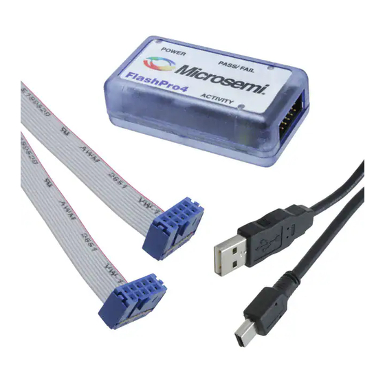
FlashPro4 programmer standalone unit
1
USB A to mini-B USB cable
1
FlashPro4 10-pin ribbon cable
Software Installation
If you are already using Microsemi's Libero
you have the FlashPro software installed as part of Libero IDE. If you are using the FlashPro4 device programmer for
standalone programming or on a dedicated machine, download and install the latest release of the FlashPro software
from the Microsemi website. The installation will guide you through the setup. Complete the software installation before
connecting the FlashPro4 device programmer to your PC.
Note:
Libero IDE v8.6 SP1 or FlashPro v8.6 SP1 are the minimum versions required to run FlashPro4.
Software releases:
http://www.microsemi.com/products/fpga-soc/design-resources/programming/flashpro#software
Hardware Installation
After installing the software successfully, connect one end of the USB cable to the FlashPro4 device programmer and
the other end to your PC's USB port. The Found Hardware Wizard will open twice. Use the wizard to install the driver
automatically (recommended). If the Found Hardware Wizard cannot find the drivers automatically, then ensure you
have properly installed the FlashPro software prior to installing the hardware. If the drivers still cannot be installed
automatically, then install them from a list or specific location (advanced).
If FlashPro was installed as part of the Libero IDE default installation, the drivers are located at
C:/Libero/Designer/Drivers/Manual. For a standalone FlashPro default installation, the drivers are located at
C:/Microsemi/FlashPro/Drivers/Manual. Microsemi recommends the automatic driver installation.
Note:
FlashPro4 uses pin 4 of the JTAG connector whereas FlashPro3 had no connection to this pin. FlashPro4 pin 4 of
the JTAG header is a PROG_MODE output drive signal. PROG_MODE toggles between programming and
normal operation. The PROG_MODE signal is intended to drive an N or P Channel MOSFET to control the output
of a voltage regulator between the programming voltage of 1.5 V and normal operation voltage of 1.2 V. This is
required for ProASIC
V, they must be programmed with a VCC core voltage of 1.5 V. Refer to
Compatibility with FlashPro3 and Using FlashPro4 PROG_MODE for 1.5 V Programming of ProASIC3L,
IGLOOV2, and IGLOO PLUS V2 Devices
Figure 1 • Pin Assignments
Pin 4 on FlashPro4 programmers MUST NOT be connected or used for anything other than its intended purpose.
April 2016
© 2016 Microsemi Corporation
®
Integrated Design Environment (IDE) and Libero System-on-Chip (SoC),
®
®
3L, IGLOO
V2, and IGLOO PLUS V2 devices because, although they can operate at 1.2
for more information.
TCK
1 2
TDO
3 4
TMS
5 6
VPUMP
7 8
TDI
9
10
AC357: FlashPro5 Backward
GND
PROG_MODE
VJTAG
TRST
GND
1
Advertisement
Table of Contents

Related Manuals for Microsemi FlashPro4


Summary of Contents for Microsemi FlashPro4
-
Page 1: Kit Contents
Integrated Design Environment (IDE) and Libero System-on-Chip (SoC), you have the FlashPro software installed as part of Libero IDE. If you are using the FlashPro4 device programmer for standalone programming or on a dedicated machine, download and install the latest release of the FlashPro software from the Microsemi website. - Page 2 Common Issues If the On LED does not light up after FlashPro4 driver installation, the driver might not be installed correctly and you must troubleshoot the installation. For more information, refer to the FlashPro Software and Hardware Installation Guide and the “Known Issues and Workarounds” section of the FlashPro software release notes: http://www.microsemi.com/products/fpga-soc/design-resources/programming/flashpro#software.
Need help?
Do you have a question about the FlashPro4 and is the answer not in the manual?
Questions and answers