
Related Manuals for CIB UNIGAS P61 Series


Summary of Contents for CIB UNIGAS P61 Series
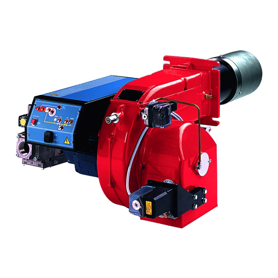
- Page 1 P61 - P65 P71 - P73A L.P.G. burners MANUAL OF INSTALLATION - USE - MAINTENANCE BURNERS - BRUCIATORI - BRULERS - BRENNER - QUEMADORES - ГОРЕЛКИ M03999CG Rel. 6.4 06/2015...
-
Page 2: Table Of Contents
TABLE OF CONTENTS DANGERS, WARNINGS AND NOTES OF CAUTION ....................3 PART I: INSTALLATION ............................5 Burner model identification ................................5 Overall dimensions (mm) ................................. 7 Performance curves..................................10 Packing ......................................12 Fitting the burner to the boiler ................................ 12 Matching the burner to the boiler .............................. -
Page 3: Dangers, Warnings And Notes Of Caution
DANGERS, WARNINGS AND NOTES OF CAUTION THIS MANUAL IS SUPPLIED AS AN INTEGRAL AND ESSENTIAL PART OF THE PRODUCT AND MUST BE DELIVERED TO THE USER. INFORMATION INCLUDED IN THIS SECTION ARE DEDICATED BOTH TO THE USER AND TO PERSONNEL FOLLOWING PRO- DUCT INSTALLATION AND MAINTENANCE. - Page 4 DIRECTIVES AND STANDARDS do not leave the equipment exposed to weather (rain, sun, etc.) unless expressly required to do so; Gas burners European directives: do not allow children or inexperienced persons to use equipment; - Directive 2009/142/EC - Gas Appliances; The unit input cable shall not be replaced by the user.
- Page 5 -EN 55014-1Electromagnetic compatibility - Requirements for household appliances, electric tools and similar apparatus. -UNI EN 676 (Gas Burners; -CEI EN 60335-1(Household and similar electrical appliances - Safety. Part 1: General requirements; - EN 50165 Electrical equipment of non-electric appliances for household and similar purposes.
-
Page 6: Part I: Installation
C.I.B. UNIGAS - M03999CG PART I: INSTALLATION Burner model identification Burners are identified by burner type and model. Burner model identification is described as follows. Type Model P61 - P65 - P71 - P73A (1) BURNER TYPE L - LPG (2) FUEL AB - Double stage (3) OPERATION... - Page 7 C.I.B. UNIGAS - M03999CG P71 L-...0.50 P71 L-...0.65 BURNERS 300 - 1200 Output min. - max kW L.P.G. Fuel Category 3B/P 11.5 - 46 Gas rate min.- max Stm Gas pressure min. - max. mbar (see Note 2) 400V 3N ~ 50Hz Power supply Total power consumption Electric motor)
-
Page 8: Overall Dimensions (Mm)
Overall dimensions (mm) Burner: P61 Boiler recommended drilling template and burner flange A(S*) A(L*) AA B(S*) B(L*) BB P61 PR - 0.40 1079 1169 736 298 812 184 204 P61 MD - 0.40 1079 1169 736 298 812 184 204 P61 AB - 0.40 1009 1099... - Page 9 Burners P65 - P71 - P73A O min. O max. Boiler recommended drilling template and burner flange A(S*) A(L*) B(S*) B(L*) Omin Omax 32 1129 1219 130 326 416 373 803 316 900 M10 330 130 237 465 531 162 155 P65 PR - 0.32 32 1129 1219 130 326 416 373 803 316 1026 694 M10 330...
- Page 10 A(S*) A(L*) AA B(S*) B(L*) BB Omin Omax Y(*S) Y(*L) 1188 1298 130 385 495 373 803 316 332 234 264 208 300 376 M10 330 233 457 130 327 519 531 198 212 155 P71 PR - 0.40 1188 1298 130 385 495 373 803 316 1026 332 234 264 208 300 376 M10 330 233 457 130 327 519 531 198 212 155...
-
Page 11: Performance Curves
C.I.B. UNIGAS - M03999CG Performance curves 200 300 400 500 600 700 800 900 1000 200 400 600 800 1000 1200 1400 1600 1800 1000 1200 1400 P73A 1000 1500 2000 2500 To get the input in kcal/h, multiply value in kW by 860. Data are referred to standard conditions: atmospheric pressure at 1013mbar, ambient temperature at 15°C. - Page 12 C.I.B. UNIGAS - M03999CG Pressure in the network - gas flow rate curves Rp 1"¼ (32) Rp 1"¼ (32) Rp 1"½ (40) Rp 1"½ (40) Rp 2" (50) Rp 2" (50) DN65 DN65 4 6 8 10 12 14 16 18 20 22 24 26 28 30 32 34 36 8 10 12 14 16 18 20 22 24 26 28 30 32 34 36 38 40 42 44 Gas rate Stm Gas rate Stm...
-
Page 13: Packing
C.I.B. UNIGAS - M03999CG Packing Burners are despatched in cardboard packages whose dimensions are: P61: 1200mm x 670mm x 540mm (L x P x H). P65 - P71 - P73A: 1280mm x 850mm x 760mm (L x P x H). Packing cases of this type are affected by humidity;... - Page 14 C.I.B. UNIGAS - M03999CG Cast-iron boilers, three pass flue boilers (with the first pass in the rear part): the blast tube must protrude no more than 100 mm into the combustion chamber. Pressurised boilers with flame reversal: in this case the blast tube must penetrate at least 50 - 100 mm into combustion chamber in respect to the tube bundle plate.
-
Page 15: Gas Train Connections
C.I.B. UNIGAS - M03999CG GAS TRAIN CONNECTIONS The next figures show the gas train components wich are included in the delivery and those wich must be fitted by the customer. The diagram complies with regulations in force ATTENTION: BEFORE EXECUTING THE CONNECTIONS TO THE GAS PIPE NETWORK, BE SURE THAT THE MANUAL CUTOFF VALVES ARE CLOSED. - Page 16 C.I.B. UNIGAS - M03999CG gas supply network ”direction” arrows for installation Keys 1A..1E Gasket Gas filter Gas valves group Bellows unit Manual valve Fig. 5 - Example of gas train To mount the gas train, proceed as follows: 1-a)in case of threaded joints: use proper seals according to the gas used; 1-b)in case of flanged joints: place a gasket (no.
-
Page 17: Siemens Vgd20
C.I.B. UNIGAS - M03999CG Mounting 1. Loosen screws A and B do not unscrew (Fig. 10 - Fig. 11). 2. unscrew screws C and D (Fig. 10 - Fig. 11). 3. Remove MultiBloc between the threaded flanges (Fig. 12). 4. After mounting, perform leakage and functional tests. MOUNTING POSITIONS Fig. -
Page 18: Pressure Adjusting Range
C.I.B. UNIGAS - M03999CG When mounting the VGD.. double gas valve, two flanges are required (as for VGD20.. model, the flanges are threaded); to prevent cuttings from falling inside the valve, first fit the flanges to the piping and then clean the associated parts; install the valve;... -
Page 19: Gas Proving System Vps504
C.I.B. UNIGAS - M03999CG The pressure adjusting range, downstream the gas valves group, changes according to the spring provided with the valve group. DUNGS MBC..SE Siemens SKP actuator Keys 1 spring 2 cap DUNGS MBC valves: 4 - 20 20 - 40 40 - 80 80 - 150 Performance range (mbar) -
Page 20: Electrical Connections
C.I.B. UNIGAS - M03999CG ATTENTION: once the gas train is mounted according to the diagram, the gas proving test mus be performed, according to the procedure set by the laws in force. ELECTRICAL CONNECTIONS WARNING: The burner is provided with a jumper between terminals 6 and 7; in the event of connecting the high/ low flame thermostat remove this jumper before connecting the thermostat. -
Page 21: Connection Diagram
C.I.B. UNIGAS - M03999CG Connection diagram Burner’s auxiliary power supply Fig. 24 Fig. 26 Fig. 25 - Probes connection scheme for modulating burners Power supply terminal block Terminal block for connections on printed circuit Fig. 27 Rotation of fan motor Once the electrical connection of the burner is executed, remember to check the rotation of the fan motor. -
Page 22: Adjustments
C.I.B. UNIGAS - M03999CG ADJUSTMENTS Combustion head gas pressure curves depending on the flow rate Curves are referred to pressure = 0mbar in the combustion head! The curves referred to the gas pressure in the combustion head, depending on the gas flow rate, are referred to the burner properly adjusted (percentage of residual O in the flues as shown in the “Recommended combustion values”... -
Page 23: Gas Pressure In Combustion Head Vs. Gas Flow Rate Curves
C.I.B. UNIGAS - M03999CG Gas pressure in combustion head vs. gas flow rate curves 8 10 12 14 16 18 20 22 24 26 28 30 32 8 10 12 14 16 18 20 22 24 26 28 30 32 34 36 38 40 Gas rate Stm Gas rate Stm P71 L-...0.xx... -
Page 24: Adjusting Air And Gas Flow Rates
C.I.B. UNIGAS - M03999CG ADJUSTING AIR AND GAS FLOW RATES ATTENTION: before starting the burner up, be sure that the manual cutoff valves are open and check that the pres- sure upstream the gas train complies the value quoted on paragraph “Technical specifications”. Be sure that the mains switch is closed. - Page 25 C.I.B. UNIGAS - M03999CG lating burners”). Then move progressively the microswitch to higher values until it reaches the high flame position; always check the combustion values and eventually adjusting the gas by means of the valves group stabiliser. go on adjusting air and gas flow rates: check, continuosly, the flue gas analisys, as to avoid combustion with little air; dose the air according to the gas flow rate change following the steps quoted below;...
-
Page 26: Double-Stage Burners
C.I.B. UNIGAS - M03999CG Double-stage burners drive the burner to the low flame stage by means of the TAB thermostat; 10 In order to change the gas flow rate slacken the nuts DB (Fig. 29) and adjust the opening angle of the gas butterfly valve by rotating the rod TG (clockwise rotation increases gas flow, anticlockwise rotation decreases it). - Page 27 C.I.B. UNIGAS - M03999CG Once the procedure till step 8 described on paragraph “Adjustment procedure” on page 23, is accomplished, go on as follows: set the low flame cam matching the high flame cam; 10 set the TAB thermostat to the minimum in order that the actuator moves progressively towards the low flame position; The manual air damper control is not provided on these actuators.
-
Page 28: Fully Modulating Burners
C.I.B. UNIGAS - M03999CG Fully modulating burners Once the procedure till step 8 described on paragraph “Adjustment procedure” on page 23 is accomplished, go on as follows: To adjust the air rate in low flame and in the intermediate points, proceed as follows. Keep pushed for 5 seconds the ESC button on the modulator (Fig. - Page 29 C.I.B. UNIGAS - M03999CG Adjusting the combustion head The burner is factory-adjusted with the combustion head in the "MAX" position, accordingly to the maximum power. To operate the bur- ner at a lower power, progressively shift back the combustion head, towards the "MIN" position, screwing the screw VRT. The ID index shows how much the combustion head moved.
- Page 30 C.I.B. UNIGAS - M03999CG P61 - P65 As far as the head pipe adjustments, insert a 1,5 mm (P61, P65) sized rod iron and close.
-
Page 31: Part Ii: Operation 30 Operation
C.I.B. UNIGAS - M03999CG PART II: OPERATION LIMITATIONS OF USE THE BURNER IS AN APPLIANCE DESIGNED AND CONSTRUCTED TO OPERATE ONLY AFTER BEING CORRECTLY CONNEC- TED TO A HEAT GENERATOR (E.G. BOILER, HOT AIR GENERATOR, FURNACE, ETC.), ANY OTHER USE IS TO BE CONSIDE- RED IMPROPER AND THEREFORE DANGEROUS. - Page 32 C.I.B. UNIGAS - M03999CG OPERATION ATTENTION: BEFORE STARTING THE BURNER UP, BE SURE THAT THE MANUAL CUTOFF VALVES ARE OPEN AND CHECK THAT THE PRESSURE VALUE UPSTREAM THE GAS TRAIN MATCHES THE VALUE ON PARAGRAPH “TECHNICAL SPECIFICATIONS”). CHECK THAT THE MAINS SWITCH IS CLOSED. CAREF Turn to the “ON”...
- Page 33 C.I.B. UNIGAS - M03999CG Keys Fig. 31 - Control panel Main switch on-off Lockout indicator light Reset pushbutton for flame control device Gas pressure switch consent indicator light Gas proving system lockout indicator light (only on burners with Gas proving system) High flame operation indicator light (or air damper open during pre-purgue phase) Low flame operation indicator light Ignition tranformer operation indicator light...
-
Page 34: Part Iii: Maintenance
C.I.B. UNIGAS - M03999CG PART III: MAINTENANCE At least once a year carry out the maintenance operations listed below. In the case of seasonal servicing, it is recommended to carry out the maintenance at the end of each heating season; in the case of continuous operation the maintenance is carried out every 6 months. -
Page 35: Removing The Filter In The Multibloc Dungs Mb-Dle 415 - 420 B01 1" 1/2 - 2
C.I.B. UNIGAS - M03999CG Removing the filter in the MULTIBLOC DUNGS MB-DLE 415 - 420 B01 1” 1/2 - 2” Check the filter at least once a year! Change the filter if the pressure difference between pressure connection 1 and 2 (Fig. 35-Fig. 36) Δp> 10 mbar. Change the filter if the pressure difference between pressure connection 1 and 2 (Fig. -
Page 36: Removing The Combustion Head
C.I.B. UNIGAS - M03999CG Removing the combustion head Type P61 Remove cover C. Unscrew the two screws S holding in position the washer and then unscrew VRT to free the threaded rod AR. Unscrew the screws V holding in position the Fig. -
Page 37: Replacing The Ignition Electrodest
C.I.B. UNIGAS - M03999CG P73A Important Note: Check the ignition and detection electrodes after removing/adjusting the combustion head. ATTENTION: avoid the ignition electrodes to contact metallic parts (blast tube, head, etc.), otherwise the burner operation would be compromised. Check the electrodes position after any intervention on the combustion head. Fig. -
Page 38: Cleaning And Replacing The Detection Photocell (P71- P73A)
C.I.B. UNIGAS - M03999CG Cleaning and replacing the detection photocell (P71- P73A) To clean/replace the detection photocell, proceed as follows: Disconnect the system from the electrical power supply. Shut off the gas supply remove the photocell from its slot (see next figure); clean the bulbe if dirty, taking care not to touch it with bare hands;... -
Page 39: Troubleshooting
TROUBLESHOOTING TROUBLE CAUSE MAIN SWITCH OPEN LACK OF GAS MAXIMUM GAS PRESSURE SWITCH DEFECTIVE (IF PROVIDED) THERMOSTATS/PRESSURE SWITCHES DEFECTIVE OVERLOAD TRIPPED INTERVENTION AUXILIARIES FUSE INTERRUPTED CONTROL BOX FAULTY DEFECTIVE SERVOCONTROL (IF PROVIDED) AIR PRESSURE SWITCH FAULT OR BAD SETTING MINIMUM GAS PRESSURE SWITCH DEFECTIVE OR GAS FILTER DIRTY IGNITION TRANSFORMER FAULT IGNITION ELECTRODES BAD POSITION... -
Page 40: Burner Exploded View
BURNER EXPLODED VIEW P61 - P65 Pos. Description Pos. Description FAN WHEEL 11.2.4 TRANSMISSION AIR ADJUSTING CAM MOTOR 11.2.5 CONNECTING ROD VALVE GROUP 11.2.6 THREADED PIPE 11.2.7 JOINT ELBOW 11.2.8 ROD JOINT M/F REDUCTION 11.3 INDEX PLATE VALVE GROUP FLANGE 11.4 INNER AIR DAMPER GAS PROVING SYSTEM... - Page 42 P73A POS. DESCRIPTION POS. DESCRIPTION STANDARD BLAST TUBE 11.2.5 JOINT FAN WHEEL 11.2.6 JOINT MOTOR 11.3 AIR INTAKE DAMPER GAS FILTER 11.4 AIR INTAKE DAMPER FLANGE 11.5 AIR INTAKE FLANGED PIPE 11.6 LOUVER SHAFT 3.4.1 GAS PRESSURE 11.7 LOUVER SHAFT 3.4.2 GAS VALVE HOUSING 11.8...
-
Page 44: Wiring Diagrams
WIRING DIAGRAMS Refer to the attached wiring diagrams. WARNING 1 - Electrical supply 230V 50Hz 1 a.c./400V 50Hz 3N a.c. 2 - Do not reverse phase with neutral 3 - Ensure burner is properly earthed... -
Page 55: Appendix
APPENDIX SIEMENS LME11/21/22 CONTROL BOX The series of equipment LME.. is used for the starup and supervisione of 1- or 2- stage gas burners. The series LME.. is interchangeable with the series LGB.. and LMG.., all diagrams and accessories are interchangea- START-UP PROGRAM ble. - Page 56 LME11 control sequence LME21 control sequence B´ B´ SB / R SB / R W / GP W / GP (LR) BV2 7101d05/0206 Control sequence Waiting time LME22 control sequence Purge time B´ TSA Ignition safety time SB / R Preignition time W / GP Postignition time...
- Page 57 LME11 connection diagram Connection diagram Error message (alarm) Fuel valve PC control EK2 Remote lockout reset button RESET Flame signal Gas pressure switch Air pressure switch Load controller K2/1 K2/2 Fan motor Control thermostat/pressurestat Safety limit thermostat R / W Limit thermostat /pressure switch Ignition transformer 7101 24 /0606...
- Page 58 CONTROL PROGRAM IN THE EVENT OF FAULT CONTROL BOX LOCKED If a fault occurs, all outputs will immediately be deactivated (in less In the event of lockout, the LME.. remains locked and the red signal lamp than 1s). (LED) will light up.The burner control can immediately be reset. This state After an interruption of power, a restart will be made with the full pro- is also mantained in the case fo mains failure.
- Page 60 C.I.B. UNIGAS S.p.A. Via L.Galvani, 9 - 35011 Campodarsego (PD) - ITALY Tel. +39 049 9200944 - Fax +39 049 9200945/9201269 web site: www.cibunigas.it - e-mail: cibunigas@cibunigas.it Note: Specifications and data subject to change. Errors and omissions excepted.
Need help?
Do you have a question about the P61 Series and is the answer not in the manual?
Questions and answers