
Related Manuals for Toro 78593


Summary of Contents for Toro 78593
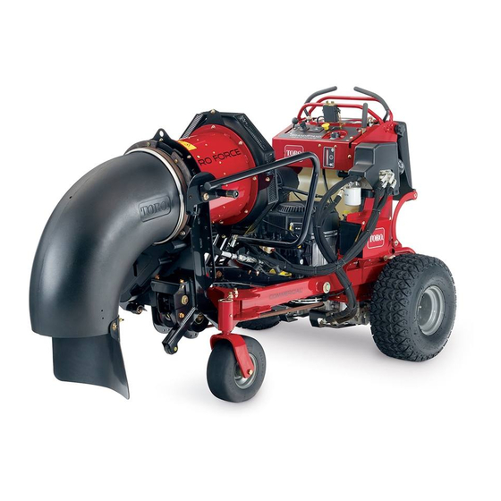
- Page 1 Form No. 3427-980 Rev B Blower Kit GrandStand ® Multi Force Mower Model No. 78593—Serial No. 403400000 and Up *3427-980* B Register at www.Toro.com. Original Instructions (EN)
- Page 2 Authorized Service recommended precautions. Dealer or Toro Customer Service and have the model and serial numbers of your product ready. Figure 1 identifies the location of the model and serial numbers on the product.
-
Page 3: Table Of Contents
Contents Safety Safety ............... 3 General Safety General Safety ........... 3 Safety and Instructional Decals ......4 This product is capable of throwing objects. Always Setup ................ 5 follow all safety instructions to avoid serious personal 1 Preparing the Machine........5 injury. -
Page 4: Safety And Instructional Decals
Safety and Instructional Decals Safety decals and instructions are easily visible to the operator and are located near any area of potential danger. Replace any decal that is damaged or missing. decal119-0217 119-0217 1. Warning—stop the engine; stay away from moving parts; keep all guards and shields in place. -
Page 5: Setup
Setup Loose Parts Use the chart below to verify that all parts have been shipped. Procedure Description Qty. – No parts required Prepare the machine. Wheel Weight Kit (sold separately) Install the Wheel Weight Kit (optional). – No parts required Position the caster wheels. -
Page 6: Positioning The Caster Wheels
Installing the Wheel Weight Removing the Right Fan Kit (Optional) Guard Parts needed for this procedure: No Parts Required Wheel Weight Kit (sold separately) Procedure Remove the fuel tank; refer to the Operator’s Procedure Manual for the machine. Installing wheel weights can improve traction on Remove and retain the 2 bolts, 2 nuts, and the the machine when using the blower;... -
Page 7: Installing The Idler Pulley
Secure the mounting bracket to the left machine frame tube, between the plates welded to the tube, using the plate, 2 carriage bolts, and 2 nuts (Figure 6). Torque the bolts to 37 to 45 N∙m (27 to 33 ft-lb). Installing the Idler Pulley Parts needed for this procedure: Idler pulley... -
Page 8: Installing The Blower
Installing the Blower Parts needed for this procedure: Blower assembly Bushing assembly Carriage bolt (3/8 x 2-1/4 inches) Locknut (3/8 inch) g246215 Figure 9 Receiver hitch 1. Carriage bolt 3. Muffler guard Heat shield 2. Nut Bumper Thread-forming screw (1/4 x 1/2 inch) Loosely install the heat shield over the muffler Stop bracket guard, with the tabs inside the muffler guard and... - Page 9 Using the center hole in the heat shield as a Use a carriage bolt (3/8 x 2-1/4 inches) and nut template, drill a hole (7/32 inch) into the muffler (3/8 inch) to install the bushing assemblies to guard (Figure 10). the machine (Figure 12).
- Page 10 Use a carriage bolt (3/8 x 1 inch) and a locknut (3/8 inch) to install the stop bracket to the right side of the machine (Figure 13). Torque the bolt to 37 to 45 N∙m (27 to 33 ft-lb). g230767 Figure 15 1.
- Page 11 WARNING Hydraulic fluid escaping under pressure can penetrate skin and cause injury. Fluid injected into the skin must be surgically removed within a few hours by a doctor familiar with this form of injury; otherwise, gangrene may result. • Ensure that all hydraulic-fluid hoses and lines are in good condition and all hydraulic connections and fittings are tight before applying pressure to the...
-
Page 12: Operation
Operation Operation Safety • The machine exceeds noise levels of 85 dB(A) at the operator’s position. Use hearing protection for prolonged exposure to reduce the potential of permanent hearing damage. • Wear appropriate clothing including eye protection; long pants; substantial, slip-resistant footwear; and hearing protection. - Page 13 Hold the kickstand and push the release lever down. Slowly lower the kickstand to the ground. Note: Once the lever disengages the hitch pin, the blower rotates down. g230858 Figure 23 1. Release lever g230843 Raising the Blower Figure 21 Raise the blower so that it latches on the hitch 1.
-
Page 14: Removing The Blower
Removing the Blower Park the machine on a level surface, disengage the PTO, engage the parking brake, and move the motion-control levers outward to the position. EUTRAL Shut off the engine and remove the key. Disconnect the blower hydraulic hoses from the quick-disconnect couplings on the Low Flow Kit. - Page 15 Remove the hitch pin, cotter pin, and hitch receiver from the A-frame. Install the hitch pin and cotter pin to secure the A-frame (Figure 28). g230751 Figure 30 1. Bolt 3. Nut g246845 2. Bushing assembly Figure 28 1. Hitch receiver 3.
- Page 16 Remove the spacer Remove the 2 bolts and 2 nuts from the right side of the machine and use them to install fan guard (Figure 34). Torque the bolts to 37 to 45 N∙m (27 to 33 ft-lb). g256854 Figure 32 g246823 Figure 34 1.
-
Page 17: Operating Tips
Operating Tips • Practice operating the blower. Blow the same direction the wind is blowing to prevent material from blowing back into the cleared area. • Be aware of the blower nozzle direction and do not point it at anyone. •... -
Page 18: Maintenance
Loosen the nut on the top pulley and slide the described in this manual. If the blower requires a pulley up to release tension on the belt (Figure major repair, contact an authorized Toro distributor. 36). • Ensure that the machine is in safe operating condition by keeping nuts, bolts, and screws tight. -
Page 19: Replacing The Clutch Belt
Replacing the Clutch Belt Checking the Hydraulic Hoses Park the machine on a level surface, disengage the PTO, and engage the parking brake. Service Interval: Every 100 hours Shut off the engine, remove the key, and wait for all moving parts to stop before leaving the Check the hydraulic hoses for leaks, loose fittings, operating position. - Page 20 While the exposure from Toro products may be negligible or well within the “no significant risk” range, out of an abundance of caution, Toro has elected to provide the Prop 65 warnings. Moreover, if Toro does not provide these warnings, it could be sued by the State of California or by private parties seeking to enforce Prop 65 and subject to substantial penalties.