Srne ML Series User Manual
Maximum power point tracking, solar charge and discharge controller
Hide thumbs
Also See for ML Series:
- User manual (13 pages) ,
- User manual (11 pages) ,
- User manual (32 pages)
Table of Contents
Advertisement
Maximum Power Point Tracking ML Serial
ML4830/ML4830-LI—ML2440/ML2440-LI
Solar Charge and Discharge Controller User Manual
Model
Battery Voltage
Max Solar Input Voltage
Charging Current
Discharging Current
Note: ML4830-LI and ML2440-LI can be used for lithium battery charging
and discharging management.
ML4830
ML4830-LI
12V/24V/36V/48V
150V
30A
20A
ML2440
ML2440-LI
12V/24V
150V
40A
20A
Advertisement
Table of Contents

Related Manuals for Srne ML Series


Summary of Contents for Srne ML Series
- Page 1 Maximum Power Point Tracking ML Serial ML4830/ML4830-LI—ML2440/ML2440-LI Solar Charge and Discharge Controller User Manual Model ML4830 ML2440 ML4830-LI ML2440-LI Battery Voltage 12V/24V/36V/48V 12V/24V Max Solar Input Voltage 150V 150V Charging Current Discharging Current Note: ML4830-LI and ML2440-LI can be used for lithium battery charging and discharging management.
-
Page 2: Table Of Contents
Dear user: Thank you for choosing our product ! Safety Instructions 1. Since the adaptable voltage of the solar charge controller exceeds human safety voltage, you are advised to read instructions before operation and operate the solar charge controller after completing safe operation training. 2. -
Page 3: Product Introduction
3.1.LED Indicator............................16 3.2 Buzzer..............................18 3.3 Key Operation............................18 3.4 LCD Starting and Main Interface Display.....................19 3.5 Load Mode Setting Page........................21 3.6 System Analysis Page..........................23 3.7 System Log Page............................23 3.8 Parameter Setting Interface........................24 3.9 Production Information Page........................25 4. Product Protection Function and System Maintenance............26 4.1 Protection Function Introduction......................26 4.2 System Maintenance..........................27 4.3Abnormality Display and Alarm......................28... - Page 4 extent. Product features : ◆ Advanced double-peak or multiple-peak tracking technology. When the panel has a shadow block or a part of the panel is damaged, I-V curve shows multiple peaks. The solar charge controller can still accurately track the maximum power point. ◆...
-
Page 5: Product Features
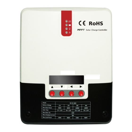
1.2 Product Features ○ ○ ○ ○ ○ ○ ○ ○ ○ ○ ○ ○ ○ ○ ○ ○ Figure 1-1 Solar Charge Controller Appearance and Interface... -
Page 6: Introduction Of The Maximum Power Point Tracking Technology
Name Name Charging Indicator Battery “-” Interface ○ ○ Battery Indicator Load “-” Interface ○ ○ Load Indicator Battery “+” Interface ○ ○ Abnormality Indicator Load “+” Interface ○ ○ Liquid Crystal Display External Temperature Sampling Interface ○ ○ Operation Button External Battery Voltage Sampling Interface ○... - Page 7 VP Curve VP曲线 VI Curve VI曲线 I(A) P(W) MPPT Point 94.5 I(A) MPPT点 81.0 67.5 54.0 40.5 P(W) PWM Charging PWM充电 27.0 13.5 11.2 14.0 16.8 19.6 U(V) Figure 1-2 Solar Panel Output Characteristic Curve Moreover, different environmental temperatures and light conditions lead to frequent changes of the maximum power point.
-
Page 8: Introduction Of Charging Stages
I(A) 20℃ 30℃ 40℃ 太 50℃ 阳 Temperature reduces, current remains constant, 温 度 降 低, 电 流 不 变, 板 and power increases 功 率 增 大 60℃ 温 度 70℃ U(V) Temperature increases and open circuit voltage reduces 温... - Page 9 Figure 1-5Battery Charging Stage Fast Charging In fast charging stage, battery voltage is below the preset value (equalizing/boost voltage) of full voltage. The solar charge controller will perform MPPT charging and provide the maximum solar power to charge battery. After battery voltage reaches the preset value, the controller conducts constant-voltage charging.
- Page 10 When the duration times reaches the preset value, the system enters floating charging stage. ☆Equalizing Charging Warning: explosion! Balance opening lead-acid batteries may produce explosive gas, and cabins of the batteries must be well ventilated. Attention: equipment damage ! Balance can push up battery voltage to a level that may damage sensitive DC load.
-
Page 11: Product Installation
due to installation environment or operation with load, the solar charge controller performs time accumulation until battery voltage reaches the preset value. After the cumulative time reaches three hours, the system automatically transfers to floating charging. If the clock of the solar charge controller is not calibrated, the controller performs regular equalizing charging in accordance with its internal clock.. -
Page 12: Wiring Specifications
When battery is charging, acidic gas can be produced. Ensure that the ◆ environment around is well ventilated. Battery may generate combustible gas. Keep it away from sparks. ◆ For outdoor installation, avoid direct sunlight and rain infiltration. ◆ Loose connections and corrosive wires may cause extreme heat that melts wire ◆... -
Page 13: Installation And Wiring
Charging Discharging Diameter Diameter Current Current (mm2) (mm2) ML4830 ML2440 2.3 Installation and Wiring Warning: Explosion risk. Do not install the solar charge controller and open type cell in the same closed space. Do not install in closed place where battery gas may gather. - Page 14 At least Hot Air 150mm At least 150mm Cold Air Figure 2.1 Installation and Heat Dissipation Step 1: Selecting an installation location. Avoid installing solar charge controller in a place where there is direct sunlight, high temperature or easy water inflow. Ensure the surrounding area of the solar charge controller is well ventilated.
- Page 15 Step 4: Wiring Remove the two screws on the solar charge controller panel, and then start wiring. For installation security, we recommend the following wiring sequence. However, wiring without following this order will not damage the solar charge controller. Control Array COMP LOAD...
- Page 16 "+" first and then "-". Power On Tip: ML series solar charge controller only starts the solar charge controller via wiring at the battery end, but ML - LI can start the solar charge controller via power of PV array,. This applies to starting the solar charge controller and activating lithium battery when lithium battery BMS is in the protection state and cannot export electricity externally.
-
Page 17: Product Operation And Display
Product Operation and Display 3.1.LED Indicator ○--- PV array Indicator Indicate solar charge controller current charging mode ○--- BAT Indicator Indicate battery current state. ○--- LOAD Indicator Indicate load switch and state. ○--- ERROR Indicator Indicate whether solar charge controller is currently normal working. -
Page 18: Buzzer
( On 0.1s, Off 0.1s, cycle 0.2s ) LOAD Indicator : Indication State Battery State Load Not Started Fast Flash Overload/Short Circuit ( On 0.1s, Off 0.1s, cycle 0.2s ) Steady On Load Normal Output ERROR Indicator : Indication State Battery State System Operation No... -
Page 19: Lcd Starting And Main Interface Display
setting mode ◄ Return Return to the previous menu ► Confirm Enter submenu; Setting/Save key 3.4 LCD Starting and Main Interface Display Starting Interface During start, the four indicators flash in flow. LCD starts after self-check. The model of the solar charge controller is displayed first, and then battery voltage level is displayed. - Page 20 charging voltage, discharging voltage, temperature compensation coefficient, communication baud rate, and etc Product Information Product information can view solar controller ⑧ serial number and version information Charging Page Display ① Charging State Charging Current Solar Panel Voltage Charging Page Indicator Battery Voltage Charging Power ②...
-
Page 21: Load Mode Setting Page
⑤ System Analysis Page ⑥ System Log Page Parameter Setting Page ⑦ ⑧ Product Information 3.5 Load Mode Setting Page Load Mode Introduction The solar controller has five load work modes,with modes referred as follows: Code Mode Description Pure light control (light on When there is no sunlight, the solar panel voltage is below the light control ON voltage, solar charge at night, off during daytime) controller will open load after delay for a certain time, when the sunlight appears, solar panel voltage... -
Page 22: System Analysis Page
○Enter Load Mode Page ○Short press the setting key to enter mode adjustment interface ○Long press the setting key for 3 seconds Load mode will flash at this time ○ Press the +/- key to set needed load mode ○Long press setting key to save and exit Setting is successful ... -
Page 23: System Log Page
In this page, press setting key to enter system analysis sub menu page, with page contents as following table 3- Displaying Items Notes Unit Total Charge WH Total Charge WH KWH(度) Total Charge AH Total Charge AH Total Dischg WH Total Dischg WH KWH(度)... -
Page 24: Parameter Setting Interface
Days value start to flash at this time, 000 refers current days ○ Press the +/- key to set the number of days 001 refers to value of previous day ○ Long press the setting key for 3 seconds, and save current days At this time, press +/- key again to view other log contents of set days 3.8 Parameter Setting Interface Under this menu, the user can view and set system parameters. -
Page 25: Production Information Page
Voltage FLOAT CHG Floating Charging 9.0~17.0V 13.8V Voltage BOOST-RE CHG Boost charging 9.0~17.0V 12.6V Recovery to Voltage LOW VOL RECT Over-Discharge 9.0~17.0V 12.6V Recovery UND VOL WARN Under-Voltage 9.0~17.0V 12.0V Warning LOW VOL DISC Over-Discharge 9.0~17.0V 11.0V Voltage DISC LMT VOL Over-Discharge 9.0~17.0V 10.5V... -
Page 26: Product Protection Function And System Maintenance
Model Solar charge controller Model: SR-ML4830 model Serial The 32 set of October 15100032 Number 2015 Hardware Hardware version V0.5.0 00.05.00 version Software Software version V0.3.0 Serial: 00.03.00 version table 3-9 Product Protection Function and System Maintenance 4.1 Protection Function Introduction Waterproof Protection Waterproofing Grade:IP32 Input limit power protection... -
Page 27: System Maintenance
When load exceeds the rated power, delayed load over-power protection will be started according to actual circumstances. Load short circuit protection Provide timely and fast protection for short circuit of load, and try to start load automatically after a certain delay. The maximum number per day is 5 times. When load short circuit occurs, the user can also remove load short circuit manually in system data analysis page exception code. -
Page 28: Abnormality Display And Alarm
4.3Abnormality Display and Alarm Error Display Remarks LED Indication Buzzer Alarm PV REV Photovoltaic Modules ERROR indicator Buzzer keeps alarming Inversed Connection steady on PV OVP Photovoltaic Modules ERROR indicator Buzzer keeps alarming Overvoltage steady on PV_MPP_OVP Over Set Vmp Voltage ERROR indicator Buzzer Alarm for steady on... -
Page 29: Parameter Adjustment Range
No-Load Loss 0.7 W~1.2W Battery Voltage 9~35 9~70 Max Solar Energy Input <150V Voltage Power Point Voltage Battery Voltage +2V ~ 120V Scope Rated Charging Current Rated Load Current capacitive load 10000uF capacity PV System Max Input 520W/12V 400W/12V Power 1040W/24V 800W/24V 1200W/36V... -
Page 30: Conversion Efficiency Curve
Low Voltage Disconnect 12.6V 12.6V 12.6V 9~17V Restoring Voltage Under-Voltage Alarming 12.2V 12.2V 12.2V 9~17V Restoring Voltage Under-Voltage Alarming 12.0V 12.0V 12.0V 9~17V Voltage Low Voltage Disconnect 11.1V 11.1V 11.1V 9~17V Voltage Discharging Limit Voltage 10.6V 10.6V 10.6V 9~17V Over-Discharge Delay Time 1~30s Equalizing Duration Time 120 minutes... - Page 31 MPPT 12V System Conversion Efficiency (12V Battery) MPPT 12V转换效率(12V蓄电池) 20Vmp 40Vmp 60Vmp 90Vmp 20 Vmp 110Vmp 40 Vmp 60 Vmp 90 Vmp 110 Vmp Output Power (W) 输出功率(W) 6.2. 24V System Conversion Efficiency MPPT 24V System Conversion Efficiency (24V Battery) MPPT 24V转换效率(24V蓄电池)...
- Page 32 MPPT 48V System Conversion Efficiency (48V Battery) MPPT 48V转换效率 (48V蓄电池) 60Vmp 70Vmp 80Vmp 90Vmp 60 Vmp 110Vmp 70 Vmp 80 Vmp 90 Vmp 110 Vmp 1000 1250 1500 2000 2500 3000 Output Power (W) 输出功率(W)...
-
Page 33: Product Size
7. Product Size Technical requirements: 技术要求: Product size: 266*182*81mm Hole position:179*160mm 产品尺寸:266*182*81mm Hole size: Φ4.5mm 开孔孔位:179*160mm Line material used: diameter <10mm 开孔大小:φ4.5mm 使用线材:直径<10mm...
Need help?
Do you have a question about the ML Series and is the answer not in the manual?
Questions and answers