Table of Contents
Advertisement
Quick Links
Advertisement
Table of Contents

Related Manuals for RADVision SCOPIA 100 MCU


Summary of Contents for RADVision SCOPIA 100 MCU
- Page 1 SCOPIA MCU Quick Start Version 5.7 Multipoint Conferencing Unit...
- Page 2 If there is any software on removable media described in this publication, it is furnished under a license agreement included with the product as a separate document. If you are unable to locate a copy, please contact RADVISION Ltd and a copy will be provided to you.
-
Page 3: What's In This Guide
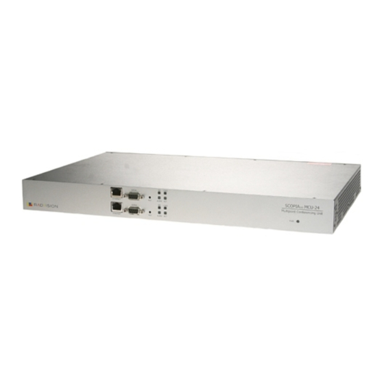
Quick Start ’ S IN THIS This Quick Start provides the basic steps required for getting your UIDE SCOPIA MCU up and running. The suggested order of operation is as follows: Preparing for Installation Introduction Unpack and Verify the Equipment Prepare a Checklist Prepare the Site Mount the SCOPIA... - Page 4 Using the MCU Create a Conference Note For more detailed information, see the SCOPIA User Guide The SCOPIA MCU unit contains two components for NTRODUCTION performing audio and videoconferencing—the MCU and the SCOPIA Media and Video Processor (MVP). The MCU (the upper component) is responsible for signaling and audio.
-
Page 5: Ethernet Leds
OMPONENT ESCRIPTION GK LED (on the Lights green when the MCU/MVP is SCOPIA MCU) registered with a gatekeeper, or when there MC LED (on the MVP) is no gatekeeper registered and the auto attendant feature is enabled. LOAD LED Lights green when more than 50% of MCU/ MVP resources are in use. -
Page 6: Prepare The Site
Before you start configuration, fill in the checklist below: REPARE A HECKLIST For the MCU IP address: _ _ _. _ _ _. _ _ _. _ _ _ IP subnet mask: _ _ _. _ _ _. _ _ _. _ _ _ Router IP address: _ _ _. - Page 7 You can optionally mount the SCOPIA MCU unit in a standard OUNT THE SCOPIA 19-inch rack. Two mounting brackets and a set of screws are 19" included in the SCOPIA MCU unit shipping box. NIT IN A PTIONAL Procedure Disconnect all cables including the power cables. Place the SCOPIA MCU unit right-side up on a hard flat surface, with the front panel facing you.
-
Page 8: Connect To Apc
The first time you install the MCU, you assign an IP address using SSIGN AN a terminal cable connection to access the boot configuration DDRESS TO THE menu. At power-up, the MCU goes through the following boot phases: Auto-boot—The embedded operating system initializes and displays basic information. - Page 9 Start the terminal emulation application on the PC. Turn on or reset the MCU. Note The debug mode prompt appears before the boot Configuration prompt. Ignore this message and wait for the boot Configuration prompt to appear. Press any key at the command prompt to display the network configuration Main menu.
- Page 10 You set the IP address, default router IP address, and subnet ONFIGURE THE MCU IP A DDRESS mask as follows: Procedure At the colon, type N to configure default network port values and press Enter. The default network port value configuration options display (Figure Enter values for default network...
-
Page 11: Connect To The Ip Network
Use the supplied LAN cable to connect the Ethernet IP network ONNECT TO THE IP N port on the front panel of the MCU to a 100Base-T IP network ETWORK connection on your network switch. Once you have assigned an IP address to the MCU, you can use ONFIGURE THE the web interface to configure the MCU using the Setup Wizard. - Page 12 Procedure When the Setup Wizard greeting page launches, click Next. The Board Settings window displays. Type the MCU IP address, subnet mask and Router IP address, if necessary, and click Next. The H.323 Settings window displays. Type the H.323 IP address and port number of the network gatekeeper on which H.323 calls to the MCU are routed and click Next.
- Page 13 The default password of the MCU is set to null. It is recommended HANGE THE EFAULT that you change the default administrator password. DMINISTRATOR ASSWORD Procedure In the sidebar, click the Device button to display the Device configuration tabs. In the Users tab select the Administrator user profile and click Edit.
-
Page 14: Save The Configuration
The Export button on the toolbar allows you to save the MCU AVE THE configuration parameters as a file to your local hard disk or a ONFIGURATION network directory. Procedure In the toolbar, click Export. The Windows File Download dialog is displayed. Check the Save this file to disk option in the Windows File Download dialog and click OK. - Page 15 You make the serial connection by connecting a PC terminal ONNECT TO A equipped with a terminal emulation application to the front panel serial port of the MVP. Procedure Connect the MVP COM port on the front panel to a PC terminal serial port using the supplied terminal cable.
- Page 16 Press any key to start configuration... Main menu N: Configure default network port values P: Change the configuration software password S: Configure network security level A: Advanced configuration menu Q: Quit Select: Figure 5 Network Configuration Main Menu Warning Configuration of any of the parameters other than <N>...
- Page 17 To modify the IP address, type the new IP address of the card followed by the subnet mask, in the format <IP address:subnet mask> as shown in Figure Press Enter to proceed to the next setting; otherwise, just press Enter to proceed to the next setting.
- Page 18 Point the MVP to the controlling MCU as follows: OINT THE TO THE ONTROLLING Procedure At the colon, type M. The MCU IP address screen displays. Enter MCU ip address Without leading zeros <current IP address>: Figure 8 MCU IP Address Screen Type the new MCU IP address and press any key to return to the main MVP configuration menu.
- Page 19 Main menu N: Configure default network port values P: Change the configuration software password S: Configure network security level M: Change MCU ip address A: Advanced configuration menu Q: Quit Select: Q Figure 9 Main MVP Configuration Menu The MVP configuration menu closes and your machine will automatically reboot.
- Page 20 You can initiate a conference by dialing to the MCU directly from TART A ONFERENCE an H.323 or SIP terminal or through a gateway from an H.320 terminal, a 3G-H.324M terminal or a regular telephone. Upon conference initiation, the conference manager can either invite other participants into the conference or supply each participant with the conference ID number for dialing directly into the conference.
Need help?
Do you have a question about the SCOPIA 100 MCU and is the answer not in the manual?
Questions and answers