Table of Contents
Advertisement
Quick Links
- 1 Cistern Service Access Options
- 2 Important - Does Your Urinal Flush for more than 20 Seconds
- 3 Button Service Access Options
- 4 Flush Volume & Stall Setup
- 5 Inwall Access - Stud Wall
- 6 Removing Internal Components through Access Window
- 7 Servicing - Inlet Valve
- 8 Servicing - Outlet Valve
- Download this manual
Advertisement
Table of Contents

Related Manuals for Caroma INVISI II Series


Summary of Contents for Caroma INVISI II Series
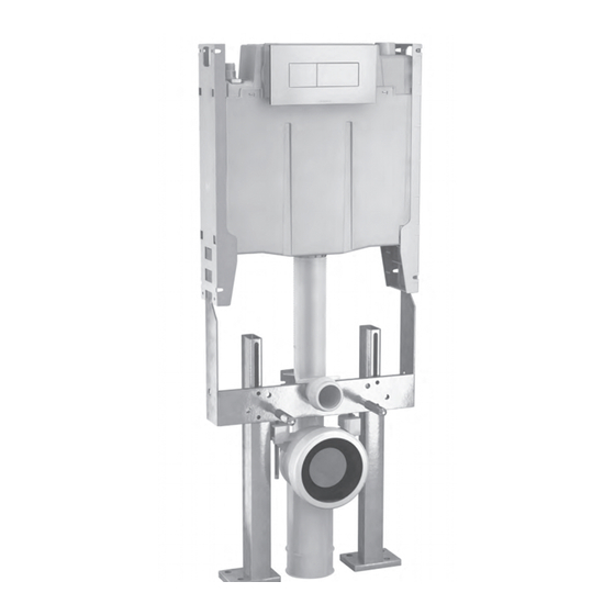
- Page 1 urinal concealed cistern 237002 Installation must be in Accordance with AS/NZS 3500.1.
-
Page 2: Table Of Contents
Contents 6 Step Easy Installation ................3 Installation Requirements ................3 Cistern Service Access Options ................4 Button Service Access Options ................5 IMPORTANT - Does your urinal flush for more than 20 seconds? ..........5 Flush Volume & Stall Setup Single Stall Installations ................ -
Page 3: Step Easy Installation
6 Step Easy Installation Check Select Select Installation Cistern Service Button Service Requirements Access Options Access Options Flush Volume Installing Preparation & Stall Setup the Cistern for Fitout Installation Requirements 237 002 - Invisi II 1.8L Single Flush Urinal Cistern CONTENTS •... -
Page 4: Cistern Service Access Options
Cistern Service Access Options Inwall Access This allows access to cistern internals through the button panel window. Standard installation requires no change to product configuration. Remote Mounting Box is supplied. Refer to page 14 for remote button panel installation. Induct Access This allows access to the whole cistern. -
Page 5: Button Service Access Options
Button Service Access Options Remote Panel Mounting INSTALLATION NOTE: This is suitable for use with any When installing between the copper pipe and the wall frame you of the button panel kits. may need to modify the Remote Mounting Box for optimum fitment. -
Page 6: Flush Volume & Stall Setup
Flush Volume & Stall Setup Single Stall Installations 1.8L = Single Stall Urinal Configuring Flush Volume The cistern is configured for single stall installations out of the factory. The pneumatic tube must be connected to the full flush position. = Full Flush Position Adjustment Screw Dust Cover... -
Page 7: Two Stall Installations
Flush Volume & Stall Setup Two Stall Installations Configuring Flush Volume 3.8L = Two Stall Urinal For two stall installations the outlet valve must first be configured by following the conversion instructions adjacent. The water level in the cistern must then be set to the “WL” mark, using the float adjustment screw located on the side of the inlet valve. -
Page 8: Three Stall Installations
Flush Volume & Stall Setup Three Stall Installations Configuring Flush Volume 5.8L = Three Stall Urinal For three stall installations the outlet valve must first be configured by following the conversion instructions adjacent. The water level in the cistern must then be set to the “1.8L” water level mark, using the float adjustment screw located on the side of the inlet valve. -
Page 9: Installing The Cistern - 237 002
237 002 Installing the Cistern - Inwall Access - stud wall Remove Dust Cover, turn Isolating Fabricate flush pipe using the Calculate the finished floor height Tap ON, fill tank & set water level using Copper Adaptor provided. (allowing for floor gradings and tile Adjusting Screw on the inlet valve. -
Page 10: Inwall Access - Masonry Wall
237 002 Installing the Cistern - Inwall Access - masonry wall Fabricate flush pipe using the Remove Dust Cover, turn Isolating Make sure the hole for the flush Copper Adaptor provided. Tap ON, fill tank & set water level using pipe is at the correct height. -
Page 11: Induct Access
237 002 Installing the Cistern - Induct Access Calculate the finished floor height Place the flush pipe through hole Connect the water supply. (allowing for floor gradings and tile and secure cistern to duct wall using 2 thickness, etc.) and add this to the screws via holes provided in each of the Water Supply Connection known height of the selected urinal’s... -
Page 12: In Ceiling Access
237 002 Installing the Cistern - In Ceiling Access Screw cistern to studs via the 2 Fabricate flush pipe using the Cistern can be a maximum height front, top and bottom holes in each Copper Adaptor provided. of 3 metres above the inlet height of mounting bracket making sure the the selected urinal. -
Page 13: Custom Panel Access
237 002 Installing the Cistern - Custom Panel Access Check cistern and all joints for leaks. The design of the custom panel The minimum front access requirements for cistern removal are: is limited only by the designers imagination. Turn Isolating Tap OFF. Continue 400mm with Preparation for Fitout on page 15. -
Page 14: Access Panel Variations
Access Panel Variations The Cistern is supplied standard with Front Access. For conversion from Front to Top Access follow this procedure. “click” Front Cover Access Box with (supplied loose) Dust Cover Top Cover Clips “click” clips Slide the Top Panel back and off the lid. Slide the Access Box up and off the lid. -
Page 15: Preparation For Fitout
Preparation for Fitout Pneumatic Tube Connections Firmly connect the pneumatic tube into the full flush position. The tube should be inserted approx. 16mm until it hits a stop. NOTE: • 1.8L Urinal Cisterns are supplied with 4m length pneumatic tube. •... - Page 16 Preparation for Fitout Remote Button Mounting Attach the tube to the cistern as shown above. Break out tab in the Top Panel or Dust Cover Panel to allow the Tube to protrude and clip back into position. Feed Pneumatic Tube through the framework and out through the Drilled Hole.
-
Page 17: Removing Internal Components Through Access Window
Removing Internal Components through Access Window - pre installation - with button panel - with blanking panel Full Flush Blanking Panel Dust Cover Panel Assembly Panel Assembly Face Plate Face Plate Ball Valve Inlet Valve Outlet Valve “squeeze” Flexible Hose Bridge Assembly Disconnect Flexible Hose from the Inlet... -
Page 18: Servicing - Inlet Valve
Inlet Valve fails to close ► Clean & inspect seal as described above, replace Cap Assembly & Seal if damaged. • If any other issues arise ► Consult a plumber or Caroma After Sales Service. Spare Parts Information • Caroma Invisi II Inlet Valve compatible Spare Part Kits are:... -
Page 19: Servicing - Outlet Valve
• If short flushing ► Check pneumatic tube is pushed into the bridge and button • If any other issues arise ► Consult a plumber or Caroma After Sales Service. Spare Parts Information • Caroma Invisi II Outlet Valve compatible Spare Part Kits are:... -
Page 20: Important Notices
Water Supply pressure minimum 30 kPa - Maximum 1000 kPa. Helplines Australia 131416 New Zealand 09 279 2700 1800 605 4218 Caroma Industries Limited www.caroma.com.au ABN 35 000 189 499 www.smartflush.com.au www.caromausa.com Locked bag 5005, Baulkham Hills NSW 2153 237 502~E...
Need help?
Do you have a question about the INVISI II Series and is the answer not in the manual?
Questions and answers