
Subscribe to Our Youtube Channel
Related Manuals for Pepperl+Fuchs F2D0-TI-Ex8.FF Series


Summary of Contents for Pepperl+Fuchs F2D0-TI-Ex8.FF Series
- Page 1 PROCESS AUTOMATION MANUAL Temperature Multi-Input Device F2D0-TI-Ex8.FF.*, RD0-TI-Ex8.FF.* 6.2.0 (DEV_REV 02)
- Page 2 Temperature Multi-Input Device With regard to the supply of products, the current issue of the following document is ap- plicable: The General Terms of Delivery for Products and Services of the Electrical Indus- try, published by the Central Association of the Electrical Industry (Zentralverband Elektrotechnik und Elektroindustrie (ZVEI) e.V.) in its most recent version as well as the supplementary clause: "Expanded reservation of proprietorship"...
-
Page 3: Table Of Contents
Temperature Multi-Input Device Introduction................. 5 Content of this Document ..............5 Target Group, Personnel..............5 Symbols Used ..................5 Product Specifications............... 7 Overview and Application ..............7 Hazardous Area Installation and Use..........7 Component Identity ................9 Installation and Commissioning ..........11 Mounting and Dismounting............... - Page 4 Temperature Multi-Input Device Primary Value Status ................28 Body Temperature Status ..............28 Device-Integrated Diagnostics............28 Alarms ....................28 Troubleshooting................ 29 LED Indications ..................29 Resource Block...................30 Sensor Block..................31 Concentrator Block ................32 AI Function Block ................33 MAI Function Block Errors ..............33 Diagnostic Summary................34 Recommended Action for Field Diagnostics according to NE 107................35 Function Block Descriptions ...........
-
Page 5: Introduction
Temperature Multi-Input Device Introduction Introduction Content of this Document This document contains information that you need in order to use your product throughout the applicable stages of the product life cycle. These can include the following: Product identification ■ Delivery, transport, and storage ■... - Page 6 Temperature Multi-Input Device Introduction Warning Messages You will find warning messages, whenever dangers may arise from your actions. It is mandatory that you observe these warning messages for your personal safety and in order to avoid property damage. Depending on the risk level, the warning messages are displayed in descending order as follows: Danger! This symbol indicates an imminent danger.
-
Page 7: Product Specifications
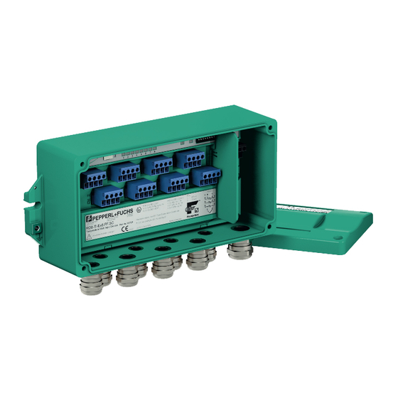
Temperature Multi-Input Device Product Specifications Product Specifications Overview and Application The 8-channel temperature multi-input device measures temperature with resistance thermometers (RTD) or thermocouples (TC) via FOUNDATION Fieldbus. Each channel can be configured independently. The device is designed for use in intrinsically safe fieldbus systems according to FISCO or Entity. - Page 8 Temperature Multi-Input Device Product Specifications Danger! Explosion hazard from wrong calculation of verification of intrinsic safety If you do not consider the maximum permissible peak values of all components when connecting intrinsically safe devices with intrinsically safe circuits of associated apparatus, this can lead to added currents or voltages.
-
Page 9: Component Identity
Temperature Multi-Input Device Product Specifications Component Identity The following section shows the dimensions, the inside connections, and the options of the device. F2D0-TI-Ex8.* Housing and Dimensions CH1 ... CH8 + H L 1. Notch for fixing the temperature multi-input device housing with M6 screw. 2. - Page 10 Temperature Multi-Input Device Product Specifications RD0-TI-Ex8.* Components and Dimensions CH1 ... CH8 + H L 1. Service interface (covered) 2. Status LEDs for channel fault indication 3. Status LED for communication 4. Status LED for power 5. Dip switches for configuration: 6.
-
Page 11: Installation And Commissioning
Do not use a damaged or polluted device. ■ The device must not be repaired, changed or manipulated. ■ If there is a defect, always replace the device with an original device from Pepperl+Fuchs. ■ Danger! Explosion hazard from damaged electronic components... - Page 12 Temperature Multi-Input Device Installation and Commissioning Ensure that the device is firmly fixed on the DIN rail. To dismount the device: Take off the device in reverse order. RD0-TI-Ex8.* Installations Depending on the application, the RD0-TI-Ex8.* must be mounted in a suitable environment. If mounted in Zone 2 for an Ex nA application, the environment must ensure the following degree of protection: IP54 in accordance with IEC 60529 for hazardous area Zone 2...
-
Page 13: Using The Separation Wall
Temperature Multi-Input Device Installation and Commissioning 3.1.1 Using the Separation Wall Danger! Explosion hazard from inadequate or missing separation appliance If you fail to apply the required separation appliance, e. g. a separation wall, between an intrinsically safe and a non–intrinsically safe circuit, this can result in a current/voltage flashover generating sparks. -
Page 14: Hardware Installation
Connect unused cables and connection lines to terminals or securely tie them down and ■ isolate them. Parameterization interface: Service interface. see image on page 10. Only trained specialists authorized by Pepperl+Fuchs may carry out parameterization tasks via the Service interface. -
Page 15: F2 Housing Degree Of Protection
Temperature Multi-Input Device Installation and Commissioning 3.2.2 F2 Housing Degree of Protection The following section contains information concerning the installation and sealing of the cable glands and the housing cover. Danger! Explosion hazard or danger to life from inadequate installation of cable glands If you do not install cable glands according to the instructions given in the instruction manual, this can generate sparks that can ignite the surrounding potentially explosive atmosphere. - Page 16 Temperature Multi-Input Device Installation and Commissioning Connectorizing Cables Using F*D0-TI-Ex8.*.CG Cable Glands 1. Strip the insulation of the cable up to about 120 mm. 2. Loosen the cap nut and the seals from the temperature multi-input device. Depending on the application, slip Seal 1 & Seal 2 or only the obligatory Seal 2 over the cable as shown: 1.
- Page 17 Temperature Multi-Input Device Installation and Commissioning Connectorizing Cables Using F*D0-TI-Ex8.*.CGB and F*D0-TI-Ex8.*.CGS Cable Glands 1. Strip the insulation of the cable up to about 120 mm. 2. Loosen the cap nut from the temperature multi-input device. 3. Remove the inner plastic piece and slip it onto the cable: move it far enough over the cable, so it completely surrounds the cable insulation.
-
Page 18: Grounding And Shielding
Temperature Multi-Input Device Installation and Commissioning 3-4 mm 1. O-ring 2. Inverted cable shield 3. Insert the cable wires with the inner plastic piece into the counterpart of the cable gland. 4. Tighten the cap nut and the counterpart. The tightening torques of cap nuts vary depending on the cable type used. -
Page 19: Electrical Connection
Temperature Multi-Input Device Installation and Commissioning Equipotential Bonding of Devices in F2* Metal Housings For electronic components in F2* metal housings in Zone 1 hazardous areas, suitable equipotential bonding in accordance with IEC/EN 60079 is required. Therefore, the device is designed as follows: The shield (terminal S) of the intrinsically safe segment is internally connected to the ■... -
Page 20: Fieldbus And Shield Connection
Temperature Multi-Input Device Installation and Commissioning Figure 3.5 Thermocouple 3.2.5 Fieldbus and Shield Connection The TM-I device provides a connection for the fieldbus cable. The device itself can operate in both polarities. Not all FOUNDATION Fieldbus devices support polarity independent operation, therefore we recommend you always wire all field devices consistently. -
Page 21: Tm-I Configuration
Temperature Multi-Input Device TM-I Configuration TM-I Configuration The following chapter explains the function block specifications, and how to parameterize the temperature multi-input device for your application. Introduction Like all FOUNDATION Fieldbus devices, the temperature multi-input device uses the following function blocks: 1 resource block ■... - Page 22 Temperature Multi-Input Device TM-I Configuration Channel Mapping Number Selected sensor Usable by Sensor 1 Sensor 2 Sensor 3 Sensor 4 Sensor 5 Sensor 6 Sensor 7 Sensor 8 Sensor 1 to 8 Body temperature In addition to the measurement value, status information is transmitted to the AI and MAI blocks that can be used to determine the quality of the measurement value.
-
Page 23: Identification, Device Id, Pd Tag
Unless the manufacturer of the control system has imported the files already, you find them on the Internet, on the Pepperl+Fuchs website. Consult the con- trol system manual for instructions on how to import the files. -
Page 24: Sensor Block Configuration
"BLOCK_ERR", "Sensor status", and "Transducer error" parameters. The "Primary Value.Status" will be set to BAD. The default adjustment is sensor diagnostics enabled. Pepperl+Fuchs recommends to use sensor diagnostics for normal operation. - Page 25 User Calibration Note! Pepperl+Fuchs recommends not to use the user calibration. The device is delivered with a suitable factory calibration. Calibrating the Temperature Multi-Input Device (User Calibration) If needed, you can calibrate the device manually ("user calibration"). Enable user-calibrated measurement by writing "Calibration on"...
-
Page 26: Concentrator Block Configuration
Measurement values are filtered internally with a 50 Hz or 60 Hz filter to suppress EMC disurbance by that frequency. The filter can be configured via the "ASIC Rejection" parameter. Pepperl+Fuchs recommends to configure the filter in accordance to the power supply system frequency used in the country of application. -
Page 27: Ai And Mai Block Configuration
Temperature Multi-Input Device TM-I Configuration Block Mode The block mode supports two modes of operation: OOS (out-of-service) and AUTO. In OOS mode, the body temperature status is always BAD and the body temperature unit can be configured. In AUTO mode, body temperature status is GOOD. Note that the concentrator block mode does not affect write protection of the sensor parameters, since they solely depend on the target block mode of the sensor block. -
Page 28: Operation
AUTO mode, the value is always GOOD, as long as there is no integrated diagnostics error detected. Device-Integrated Diagnostics The Pepperl+Fuchs TM-I device continuously monitors its internal hardware and body temperature. If an error occurs the following happens: The status of all primary values switches to BAD ■... -
Page 29: Troubleshooting
■ (green) Check fieldbus cable wiring ■ Permanentl Power available y ON COM (red) Communication active Permanentl Hardware error Send device to Pepperl+Fuchs for y ON repair Flashing No communication Check LAS ■ ON/OFF Communication errors Check wiring ■ Sensor No sensor errors (red)... -
Page 30: Resource Block
Parameterization data stored in Repeat parameterization. If Data the device was faulty and was this error occurs repeatedly, replaced by default settings send the device to Pepperl+Fuchs for repair Device needs Hardware error Send device to maintenance Pepperl+Fuchs for repair Simulate... -
Page 31: Sensor Block
Temperature Multi-Input Device Troubleshooting Sensor Block Problem Remedy Parameter Message Cause Procedure BLOCK_ERR Block "Sensor Type" is set to Correct parameterization ■ configuration "Undefined" error "Sensor Range.Unit" is set ■ to a value not supported by sensor (e.g., "mV" for a resistance based sensor) User calibration is turned ■... -
Page 32: Concentrator Block
Temperature Multi-Input Device Troubleshooting Common Sensor Block Problems Problem Remedy Cause Procedure Block does not A configuration error is Clear configuration error cause, see leave OOS mode reported above Resource block is in OOS Set resource block to AUTO mode mode Sensor failure Sensor error (overrange,... -
Page 33: Ai Function Block
Temperature Multi-Input Device Troubleshooting AI Function Block Problem Remedy Parameter Message Cause Procedure BLOCK_ERR Block The channel parameter Set valid value, see chapter configuration contains an invalid value error The function block does not Include block into application have a schedule downloaded and download schedule to device "L_TYPE"... -
Page 34: Diagnostic Summary
Temperature Multi-Input Device Troubleshooting Common MAI Problems Problem Remedy Cause Procedure Function block does not leave A "BLOCK_ERR" is reported Clear block error cause, see OOS mode above Resource block is in OOS Set resource block to AUTO mode mode The function block does not Include block into application have a schedule downloaded... -
Page 35: Recommended Action For Field Diagnostics According To Ne 107
Action Maintenance required Configuration error Check blocks for configuration errors. Failed Device failure Body temperature Send the device to > +95°C Pepperl+Fuchs for repair. Body temperature > - 50°C NV storage verification failed NV storage write failed Hardware error detected... -
Page 36: Function Block Descriptions
MANUFAC_ID Manufacturer identification number. Used by an interface device to locate the DD file for the resource. The Pepperl+Fuchs ID is 0x502B46. DEV_TYPE Manufacturer model number associated with the resource. Used by interface devices to locate the DD file for the resource.... - Page 37 Pepperl+Fuchs TI Mux does not support output blocks. SET_FSTATE Allows the fault state condition to be manually initialized by selecting Set. The Pepperl+Fuchs TI Mux does not support this function. CLR_FSTATE Writing a Clear to this parameter will clear the device fault state if any field condition has cleared.
- Page 38 Index Parameter Description LIM_NOTIFY Maximum number of unconfirmed alert notification messages allowed. Pepperl+Fuchs TI Mux supports a maximum of 42. CONTIRM_TIME The minimum time between retries of alert reports. Retries are not possible when parameter is set to 0. WRITE_LOCK If set, no writes from anywhere are allowed, except to clear WRITE_LOCK.
-
Page 39: Analog Input Function Block (Ai)
Temperature Multi-Input Device Function Block Descriptions Analog Input Function Block (AI) Rel. Index Parameter Units Description ST_REV The revision level of the static data associated with the resource block. The revision value is incremented, each time a static parameter value in the block is changed. - Page 40 Temperature Multi-Input Device Function Block Descriptions Rel. Index Parameter Units Description CHANNEL The CHANNEL value is the number of the physical input (transducer output) that is used as input for the function block. Supported values are: 1-8: physical input from Channel 1 to Channel 8 ■...
-
Page 41: Multiple Analog Input Function Block (Mai)
Temperature Multi-Input Device Function Block Descriptions Rel. Index Parameter Units Description LO_LO_ALM LO-LO alarm data including a value of the alarm, a time stamp of occurrence, and the state of the alarm. Table 7.2 Analog input function block (AI) parameter list Multiple Analog Input Function Block (MAI) Rel. -
Page 42: Ti_Sens Sensor Blocks (Tis)
Temperature Multi-Input Device Function Block Descriptions TI_SENS Sensor Blocks (TIS) The properties column contains the following parameter properties: S: Static (a write access to this parameter increments ST_REV) ■ W: Writeable parameter ■ OOS: Parameter is writeable in out-of-service (OOS) mode only ■... - Page 43 Temperature Multi-Input Device Function Block Descriptions Rel. Index Parameter Units Description BLOCK_ALM The block alarm is used for all configuration, hardware connection feature, or system problems in the block. The cause of the alert is entered in the subcode field. The first alert to become active will set the Active status in the Status parameter.
- Page 44 Temperature Multi-Input Device Function Block Descriptions Rel. Index Parameter Units Description Sensor Status Shows failures of the attached sensor, it is a bit string so multiple errors can be shown. Supported values are: Sensor connection error ■ Over range: The measured value is too high for ■...
- Page 45 Temperature Multi-Input Device Function Block Descriptions Rel. Index Parameter Units Description Calibration Units Unit used to calibrate the input. It is set automatically when a calibration starts. Valid values: mV and Ohm Calibration Mode S, OOS Stipulates the validity of user calibration and turns the calibration mode on for the input.
-
Page 46: Concentrator Block (Tic)
Temperature Multi-Input Device Function Block Descriptions Concentrator Block (TIC) The properties column contains the following parameter properties: S: Static (a write access to this parameter increments ST_REV) ■ W: Writeable parameter ■ OOS: Parameter is writeable in out-of-service (OOS) mode only ■... - Page 47 Temperature Multi-Input Device Function Block Descriptions Rel. Index Parameter Units Description Block Mode S, W Mode block of sensor input 1. Channel 1 Primary Value The value and status of sensor input 1. Primary Value S, SP The damping value for sensor input 1. Filtertime Parameter is writeable if corresponding Channel 1...
- Page 48 PROCESS AUTOMATION – PROTECTING YOUR PROCESS Worldwide Headquarters Pepperl+Fuchs GmbH 68307 Mannheim · Germany Tel. +49 621 776-0 E-mail: info@de.pepperl-fuchs.com For the Pepperl+Fuchs representative closest to you check www.pepperl-fuchs.com/contact www.pepperl-fuchs.com Subject to modifications / DOCT-5665 Copyright PEPPERL+FUCHS • Printed in Germany 05/2017...
Need help?
Do you have a question about the F2D0-TI-Ex8.FF Series and is the answer not in the manual?
Questions and answers