Table of Contents
Advertisement
Quick Links
HPE Edgeline EL4000 System User
Guide
Abstract
This document is for the person who installs, administers, and troubleshoots servers and
storage systems. Hewlett Packard Enterprise assumes you are qualified in the servicing of
computer equipment and trained in recognizing hazards in products with hazardous energy
levels.
Part Number: 868755-007
Published: June 2019
Edition: 1
Advertisement
Table of Contents

Related Manuals for Hewlett Packard Enterprise Edgeline EL4000


Summary of Contents for Hewlett Packard Enterprise Edgeline EL4000
- Page 1 Abstract This document is for the person who installs, administers, and troubleshoots servers and storage systems. Hewlett Packard Enterprise assumes you are qualified in the servicing of computer equipment and trained in recognizing hazards in products with hazardous energy levels.
- Page 2 Packard Enterprise products and services are set forth in the express warranty statements accompanying such products and services. Nothing herein should be construed as constituting an additional warranty. Hewlett Packard Enterprise shall not be liable for technical or editorial errors or omissions contained herein.
-
Page 3: Table Of Contents
Contents Component identification...............6 Base configurations........................6 PCIe configuration......................6 PXIe configuration......................9 Operations..................... 14 Install an AC power supply......................14 Install the DC power supply......................14 Install a power supply blank......................19 Power down the system......................20 Power up the system........................20 Mount the system........................20 Remove the access panel......................21 Removing the PCIe access panel.................. - Page 4 Setting the static IP address using the serial console cable..........42 Viewing or updating the DHCP address using the serial console cable........43 Finding the IP address through DHCP..................44 Software and configuration utilities............ 45 Product QuickSpecs........................45 Supported operating systems and drivers matrix ...............45 HPE iLO............................
- Page 5 Shock and vibration specifications................... 62 Acoustic emission specifications ..................62 System synchronization clock specifications..............64 Websites....................66 Support and other resources...............67 Accessing Hewlett Packard Enterprise Support................. 67 Information to collect......................67 Accessing updates........................67 Customer self repair........................68 Remote support.......................... 68 Acronyms and abbreviations...............69...
-
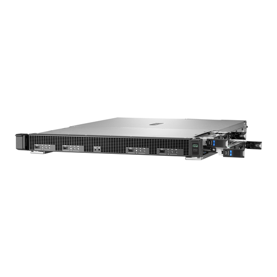
Page 6: Component Identification
Component identification This chapter describes the external and internal server features and components. Base configurations The HPE Edgeline EL4000 System comes in the following configurations: • HPE Edgeline EL4000 4x10GbE 2xQSFP+ PassThru System Supports 1 to 4 full-height, half-length PCIe cards. The core network is pass-through. A separate 1G RJ-45 network port is provided for access to the iLO management network. - Page 7 Front panel LEDs and buttons Item Description Status USB 2.0 port Connects a USB 2.0 device to the blade Blade power LED/button Green = Normal operation Amber = Standby operation Off = No power or no blade installed Blade health LED Green = Normal operation Flashing Amber = Degraded condition Flashing Red = Critical condition...
- Page 8 Rear panel components Item Description Power supply PCIe slot #4 (bottom) PCIe slot #3 (top) iLO port Chassis UID LED PCIe slot #1 (top) PCIe slot #2 (bottom) Power supply QSFP+ Uplink B or SFP+ Uplink B QSFP+ Uplink A or SFP+ Uplink A Rear components include either QSFP+ or SFP+ ports, depending on configuration.
-
Page 9: Pxie Configuration
Item Description System battery DIP Switch System board DIP switch Position Default Function • Off = Uplink propagation disabled • On = Uplink propagation enabled Blade slot identification Item Description Left side, top—Bridge 1 Left side, bottom—Bridge 2 Right side, top—Bridge 3 Right side, bottom—Bridge 4 PXIe configuration Front panel components... - Page 10 Item Description Blade 1 Blade 2 10 MHz REF OUT clock SFP+ Uplink A connector SFP+ Uplink B connector 10 MHz REF IN clock iLO connector Blade 3 Blade 4 Front panel LEDs and buttons Item Description Status USB 2.0 port Connects a USB 2.0 device to the blade Blade power LED/button Green = Normal operation...
- Page 11 Item Description Status Blade UID LED Blue = Blade ID is selected. Flashing Blue = Blade firmware update is in progress or iLO IRC is in use. Off = Blade ID is not selected. Management reset pin hole Pressing the reset button resets the chassis controller. iLO button remains operational.
- Page 12 Item Description Power supply 1 LED Chassis UID LED Power supply 2 LED System board components (PXIe) Item Description System board DIP Switch System battery DIP switch Position Default Function • Off = Fan normal mode • On = Fan high mode Component identification...
- Page 13 Blade slot identification Item Description Left side, top—Blade 1 (controller for all PXIe cards in the chassis) Left side, bottom—Blade 2 Right side, top—Blade 3 Right side, bottom—Blade 4 Component identification...
-
Page 14: Operations
Operations Install an AC power supply Procedure 1. Align the power supply to the system. 2. Insert the power supply until it locks in place. 3. Connect the power cord and tie wrap the cable. You must press the Power On/Off button twice to power on the system. Install the DC power supply Procedure Remove the ring tongue from the top of the power supply. - Page 15 Crimp the ring tongue to the ground cable from the -48V power source. Remove the black connector from the rear of the power supply. Operations...
- Page 16 Loosen the screws on the connector. Attach the (earthed) cable to the ground screw and washer and tighten to 13 lb-in of torque. The ground cable must be connected before connecting the -48V wire and return wire. Operations...
- Page 17 Insert the -48V wire into the left side of the connector and tighten the screw to 10 lb-in of torque. Insert the return wire into the right side of the connector and tighten the screw to 10 lb-in of torque. Operations...
- Page 18 Insert the power supply into the power supply bay until it clicks into place. Insert the connector into the power supply. Operations...
-
Page 19: Install A Power Supply Blank
To obtain a cable management arm, contact a Hewlett Packard Enterprise authorized reseller. 12. Make sure the -48V DC power source is off or the PDU breaker is in the off position, and then connect the power cord to the -48V DC power source or PDU. -
Page 20: Power Down The System
Power down the system Before powering down the system for any upgrade or maintenance procedures, back up critical system data and programs. Before performing chassis maintenance, shut down all blades installed in the system. Procedure • Use one of the following methods to power down the system: ◦... -
Page 21: Remove The Access Panel
• Rack-mounting kit • Wall-mounting kit The wall-mounting kit is non HPE and allows up to two Edgeline EL4000 systems to be installed on a ® wall. For more details, contact RackSolutions at http://www.racksolutions and request P/N 101-5302. Remove the access panel Depending on the configuration of your system, perform one of the following procedures: •... -
Page 22: Remove The Fixed Top Cover
Remove the fixed top cover Depending on the configuration of your system, perform one or more of the following procedures: • Removing the fixed top cover of the PCIe system on page 22 • Removing the fixed front top cover of the PXIe system on page 23 •... -
Page 23: Removing The Fixed Front Top Cover Of The Pxie System
Removing the fixed front top cover of the PXIe system Procedure Using a Torx screwdriver, remove the 10 T-10 Torx screws securing the fixed front top cover to the system. Removing the fixed rear top cover of the PXIe system Procedure 1. -
Page 24: Install The Fans
Install the fans Procedure 1. Align the fan with the fan slots of the system. 2. Squeeze the tabs on either side of the fan, and then slide it into the bay until it clicks in place. 3. Connect the fan cable to the board. Operations... -
Page 25: Install The Blade
Install the blade Procedure 1. Align and install the blade into the system. a. For blades 1 and 2 (left side), the blades must be inserted with the processor facing up. b. For blades 3 and 4 (right side)*, the blades must be inserted with the processor facing down. *Blades 3 and 4 will appear upside down from image. - Page 26 Operations...
-
Page 27: Setup
Setup Optional services For information on the optional services offered, see the product QuickSpecs on the Hewlett Packard Enterprisewebsite (http://www.hpe.com/info/qs). Optimum environment When installing the system, select a location that meets the environmental standards. • Space and airflow requirements on page 27 •... -
Page 28: Hardware Options Installation
Hardware options installation Installing the filter kit Procedure Install the component as indicated. Installing the short extension rail kit For detailed instructions, see the instructions that ship with the rack rail hardware kit. Procedure 1. Attach the rails to the system. 2. - Page 29 • T-15 screwdriver • Philip screwdriver • NVMe SSD module Procedure Power down the system. Remove all power: a. Disconnect each power cord from the power source. b. Disconnect each power cord from the system. If the system is mounted on a wall or a rack, dismount the system. Remove the access panel.
- Page 30 Remove the PCIe blank from the PCIe slot. Install the NVMe M.2 SSD on bay 1 of the adapter card: a. Insert the SSD into the SSD slot at a 45 degree angle. b. Carefully press the SSD down to the horizontal position: c.
- Page 31 Install the M.2 adapter, with the SSD modules installed, on the PCIe riser cage and secure it with Philips screw. 10. Install the PCIe riser cage back in the system. 11. Install the access panel: a. Place the access panel in position and close the latch. b.
- Page 32 12. Mount the system as per your requirements. 13. Connect power cord to the system. 14. Connect power cord to the power source. 15. Power up the system. Hardware options installation...
-
Page 33: Configuration
Configuration Networking in the chassis HPE EL4000 4x10G 2xQSFP+ PThru System networking This configuration has two external 40GbE QSFP+ ports, labelled A and B. The NIC A of each of the four blades is connected to the external port A. The NIC B of each blade is connected to the external port B through a single 10G lane within the 40GbE port. -
Page 34: Accessing The System Utilities Menu
• EdgeLine_Chassis_Firmware_4.30S.BIN • EL4000_Chassis_Data_v20_20190220.HPb • EL4000_EN_SwitchA_v328.HPb • EL4000_EN_SwitchA_v328.HPb NOTE: EL4000 switched chassis does not support LACP teaming. HPE EL4000 10G 2SFP+ Switch PXIe System networking (data capture and control) This configuration has two external 10GbE SFP+ ports, labelled A and B. The NIC A of each of the four blades is internally switched to the external 10GbE SFP+ port labelled A. -
Page 35: Finding The Ip Address For An Ilo On Edgeline System Blades
5. Press the ESC + 9 keys. The System Utilities menu displays. Finding the IP address for an iLO on Edgeline system blades Edgeline system blades contain an iLO processor. However, not all system blades have a local keyboard, video, and mouse solution to help identify the IP address assigned to the iLO. Running a simple DHCP server on your laptop, connected directly to the management (iLO) port on your chassis allows you to temporarily assign an IP address to the management device. -
Page 36: Using Dynamic Dns To Access The Ilo
Edgeline blades have an identification tag that provides the following information: • The Dynamic DNS name that the iLO will use: If your network supports dynamic DNS, you can access the iLO by entering the dynamic DNS name into your browser. •... -
Page 37: Configuring The Dhcp Server For Windows On Your Laptop
In the example provided, the MAC address matches the iLO MAC. So the IP address is 192.168.0.13. To learn more about HPE iLO 4 go to the Hewlett Packard Enterprise Information Library. Configuring the DHCP server for Windows on your laptop The DHCP Server for Windows application does not have to be installed in the system. - Page 38 Disconnect your laptop from the network. Connect the laptop directly to your gateway chassis. To set up the DHCP server, click the dhcpwiz.exe file. Click the Next button. The Network Interface cards window appears. Select your network interface, and then click the Next button. Configuration...
- Page 39 The Supported Protocols window appears. 10. Select the HTTP box, and optionally, the DNS box, and then click the Next button. The Configuring DHCP for Interface window appears. 11. Enter the range of IP addresses that your DHCP server can use to assign to DHCP clients, and then click the Next button.
- Page 40 The Writing the INI file window appears. 12. Click the Write INI file button, and then click the Next button. Clicking the Write INI file button saves the configuration file, and enables you to start the service. Configuration...
- Page 41 The DHCP server window appears. 13. Click the Admin button. A confirmation window appears. 14. Click Yes at the conformation window. Configuration...
-
Page 42: Setting The Static Ip Address Using The Serial Console Cable
15. Click the Continue as tray app button in the same window. The DHCP server icon appears on the system tray. 16. Right-click the DHCP server icon on the system tray. 17. To open the web interface of your DHCP server, select Open Status from the menu. The DHCP Server Status webpage appears displaying the IP address of any device (your iLO) that has been assigned an IP address from your server. -
Page 43: Viewing Or Updating The Dhcp Address Using The Serial Console Cable
4. Configure the IP Address, Subnet Mask, and Gateway Address as required. The following image is an example of a completed Network Options screen. 5. Once completed, press ESC to back out of the menus. Save the settings when prompted. 6. -
Page 44: Finding The Ip Address Through Dhcp
Finding the IP address through DHCP Procedure 1. Access the System Utilities menu. 2. Navigate through the menu options System Configuration > iLO 4 Configuration Utility > Network Options. 3. The Network Options screen displays the IP address. Configuration... -
Page 45: Software And Configuration Utilities
ROM, BIOS, and driver support For more information on Hewlett Packard Enterprise Certified and Supported systems for the latest software ROM, BIOS, and drivers available for your system, see the Hewlett Packard Enterprise Support Center website: http://www.hpe.com/support/hpesc HPE iLO iLO is a remote server management processor embedded on the system boards of HPE ProLiant and Synergy servers. -
Page 46: Ilo Restful Api Support
It takes less than 5 minutes to download the Active Health System Log and send it to a Hewlett Packard Enterprise support professional to help you resolve an issue. When you download and send Active Health System data to Hewlett Packard Enterprise, you agree to have Hewlett Packard Enterprise use the data for analysis, technical resolution, and quality improvements. -
Page 47: Hpe Edgeline Component Pack
Edgeline System. Users deploy the firmware updates contained in the HPE Edgeline Component Pack using the firmware update capability of the iLO 4 on each server blade, or by using HPE Edgeline Infrastructure Manager. Download the latest pack from the Hewlett Packard Enterprise website. -
Page 48: Hpe Edgeline Workload Orchestrator
HPE Edgeline Workload Orchestrator HPE Edgeline Workload Orchestrator enables users to centrally deploy and manage workloads running on multiple Edgeline systems. Users can deploy workflows and application containers to one or more Edgeline systems located in the same or geographically distributed locations. For example, a user can create a workflow and application set on an HPE Edgeline OT Link Platform and then deploy it on additional systems with the Edgeline Workload Orchestrator. -
Page 49: Flexible Boot Control
Action Access System Utilities F9 during server POST Navigate menus Up and Down arrows Select items Enter Save selections Access Help for a highlighted configuration option Scan the QR code on the screen to access online help for the UEFI System Utilities and UEFI Shell. Default configuration settings are applied to the server at one of the following times: •... -
Page 50: Restoring And Customizing Configuration Settings
These features enhance the capabilities of the UEFI System Utilities. For more information, see the following documents: • UEFI Shell User Guide for HPE ProLiant Gen9 Servers on the Hewlett Packard Enterprise website • UEFI Shell Specification on the UEFI website Software and configuration utilities... -
Page 51: Embedded Diagnostics Option
For more information on the Embedded Diagnostics option, see the UEFI System Utilities user guide for your system on the Hewlett Packard Enterprise website. iLO RESTful API support for UEFI The ProLiant Gen9 servers include support for a UEFI-compliant System BIOS, along with UEFI System Utilities and Embedded UEFI Shell preboot environments. -
Page 52: Troubleshooting
The HPE Edgeline System Troubleshooting Guide provides procedures for resolving common problems and comprehensive courses of action for fault isolation and identification, issue resolution, and software maintenance on the Edgeline System. The document is available in the Hewlett Packard Enterprise Information Library. -
Page 53: Battery
Battery Battery specifications Feature Specification Type Maintenance-free, sealed, CR2032 lithium manganese dioxide button battery Voltage 3.0 V Replace the system battery Procedure 1. Locate the battery on the system board: • System board components (PCIe) on page 8 • System board components (PXIe) on page 12 2. - Page 54 For more information about battery replacement or proper disposal, contact an authorized reseller or an authorized service provider. Battery...
-
Page 55: Warranty And Regulatory Information
Regulatory information Safety and regulatory compliance For important safety, environmental, and regulatory information, see Safety and Compliance Information for Server, Storage, Power, Networking, and Rack Products, available at the Hewlett Packard Enterprise website (http://www.hpe.com/support/Safety-Compliance-EnterpriseProducts). Belarus Kazakhstan Russia marking Manufacturer and Local Representative Information Manufacturer information: Hewlett Packard Enterprise Company, 3000 Hanover Street, Palo Alto, CA 94304 U.S. -
Page 56: Turkey Rohs Material Content Declaration
• Belarus: • Kazakhstan: Manufacturing date: The manufacturing date is defined by the serial number. CCSYWWZZZZ (serial number format for this product) Valid date formats include: • YWW, where Y indicates the year counting from within each new decade, with 2000 as the starting point;... -
Page 57: Electrostatic Discharge
Electrostatic discharge Preventing electrostatic discharge To prevent damaging the system, be aware of the precautions you must follow when setting up the system or handling parts. A discharge of static electricity from a finger or other conductor may damage system boards or other static-sensitive devices. This type of damage may reduce the life expectancy of the device. -
Page 58: Specifications
Specifications Product QuickSpecs For more information about product features, specifications, options, configurations, and compatibility, see the product QuickSpecs on the Hewlett Packard Enterprise website (http://www.hpe.com/info/qs). Environmental specifications Table 2: Standard specifications Specification Value Temperature range — Operating 10°C to 35°C (50°F to 95°F) Nonoperating -30°C to 60°C (-22°F to 140°F) - Page 59 Table 4: ASHRAE Class A4 specifications Specification Value Temperature range — Operating 5°C to 45°C (41°F to 113°F) 10°C to 35°C (50°F to 95°F) when GPU is installed Nonoperating -30°C to 60°C (-22°F to 140°F) — Relative humidity (noncondensing) Operating 8% to 90% at 28°C (82.4°F) maximum wet bulb temperature Non-Operating...
-
Page 60: Environmental Specifications-System Components Support Matrix
HPE 800W Flex Slot Platinum Hot Plug Power Supply on page 61 • HPE 800W Flex -48VDC Hot Plug Power Supply on page 61 For detailed power supply specifications, see the QuickSpecs on the Hewlett Packard Enterprise website (http://www.hpe.com/info/proliant/powersupply). Specifications... -
Page 61: Hpe 800W Flex Slot Platinum Hot Plug Power Supply
HPE 800W Flex Slot Platinum Hot Plug Power Supply Specification Value Input voltage range 100 to 240 (V rms) Frequency range 50 to 60 (Nominal) (Hz) Nominal input voltage (V rms) Maximum rated output wattage rating (Watts) Nominal input current (A rms) Maximum rated input wattage rating (Watts) -
Page 62: Pxi/Pxie Specifications
Maximum rated VA (Volt-Amp) Efficiency (%) 90.7 91.9 93.2 Power factor Leakage current (mA) Maximum inrush current (A peak) Maximum inrush current duration (ms) Maximum British Thermal Unit 3008 2971 2929 rating (BTU-Hr) PXI/PXIe specifications NOTE: Specifications are subject to change without notice. Electrical load regulation specifications Voltage (V) Load regulation (%) - Page 63 Table 6: Base configuration 1 (m510) Component Quantity Specification Blade m510 DIMMs/cartridge SATA M.2/cartridge 64 GB NVME M.2/cartridge PXI 6341 800 W AC Table 7: Base configuration 2 (m710x and m710x-L) Component Quantity Specification Blade m710x and m710x-L DIMMs/cartridge SATA M.2/cartridge 64 GB NVME M.2/cartridge PXI 6341...
-
Page 64: System Synchronization Clock Specifications
System synchronization clock specifications 10 MHz system reference clock: PXI_CLK10 Specification Value Maximum slot-to-slot skew 1 ns Accuracy ±25 ppm max (guaranteed over the operating temperature range) Maximum jitter 5 ps RMS phase jitter (10 Hz to 1 MHz range) Duty factor 45% to 55% Unloaded signal swing... - Page 65 External clock source Specification Value Frequency 10 MHz ±100 PPM Input amplitude — Front panel BNC 200 mVPP to 5 VPP square-wave or sine-wave Front panel SMA input impedance 50 Ω ± 5 Ω Specifications...
-
Page 66: Websites
Websites General websites Hewlett Packard Enterprise Information Library www.hpe.com/info/EIL Single Point of Connectivity Knowledge (SPOCK) Storage compatibility matrix www.hpe.com/storage/spock Storage white papers and analyst reports www.hpe.com/storage/whitepapers For additional websites, see Support and other resources. Websites... -
Page 67: Support And Other Resources
Hewlett Packard Enterprise Support Center More Information on Access to Support Materials page: www.hpe.com/support/AccessToSupportMaterials IMPORTANT: Access to some updates might require product entitlement when accessed through the Hewlett Packard Enterprise Support Center. You must have an HPE Passport set up with relevant entitlements. Support and other resources... -
Page 68: Customer Self Repair
Customer self repair Hewlett Packard Enterprise customer self repair (CSR) programs allow you to repair your product. If a CSR part needs to be replaced, it will be shipped directly to you so that you can install it at your convenience. -
Page 69: Acronyms And Abbreviations
Acronyms and abbreviations chassis management Electromagnetic compatibility Integrated Lights-Out LpAm declared average bystander position A-Weighted sound pressure levels long-term evolution LWAd declared A-Weighted sound power levels peripheral component interconnect PCIe Peripheral Component Interconnect Express preboot execution environment PCI eXtensions for instrumentation PXIe PCI eXtensions for instrumentation express QSFP+... - Page 70 wireless wide area network Acronyms and abbreviations...
-
Page 71: Documentation Feedback
Documentation feedback Hewlett Packard Enterprise is committed to providing documentation that meets your needs. To help us improve the documentation, send any errors, suggestions, or comments to Documentation Feedback (docsfeedback@hpe.com). When submitting your feedback, include the document title, part number, edition, and publication date located on the front cover of the document.
Need help?
Do you have a question about the Edgeline EL4000 and is the answer not in the manual?
Questions and answers