Honeywell MIWI350 Installation And Operation Manual
Hide thumbs
Also See for MIWI350:
- Installation and operation manual (86 pages) ,
- Quick start manual (7 pages) ,
- Quick start manual (6 pages)
Table of Contents
Advertisement
MIWI350 Installation and Operations Guide
FD-610 | Version 2.01 | July 2019
Honeywell Process Solutions | Mercury Instruments
1280 Kemper Meadow Drive,
Cincinnati, OH 45240
855 251-7065 – United States & Canada
|
302 669-4253 – Outside the United States
MI-TAC-Support@Honeywell.com | www.honeywellprocess.com
Advertisement
Table of Contents

Related Manuals for Honeywell MIWI350


Summary of Contents for Honeywell MIWI350
- Page 1 MIWI350 Installation and Operations Guide FD-610 | Version 2.01 | July 2019 Honeywell Process Solutions | Mercury Instruments 1280 Kemper Meadow Drive, Cincinnati, OH 45240 855 251-7065 – United States & Canada 302 669-4253 – Outside the United States MI-TAC-Support@Honeywell.com | www.honeywellprocess.com...
- Page 2 Honeywell Process Solutions.
-
Page 3: Table Of Contents
1.5.2 Conditions of Acceptability 1.5.3 Warning-Explosion Hazard/Avertissement - Risque d'explosion 1.5.4 Security Control Measures 1.5.5 Things to Remember 1.5.5.1 Usage of MIWI350 in Hazardous Areas 1.5.5.2 Installation and Commissioning of MIWI350 in Hazardous Areas 1.5.5.3 Service, Maintenance, and Troubleshooting 2 Installation 2.1 Unpacking 2.2 Mounting Options... - Page 4 7.3 MIWI350 as Power or Communication Box 7.3.1 Barrier Connections 7.3.1.1 With CloudLink Modem 7.3.1.2 With RV50 Modem 7.3.2 Terminal Block Connections 7.3.2.1 With CloudLink Modem 7.3.2.2 With RV50 Modem 8 External Connections 9 Configuration Software 10 Orderable Kits...
-
Page 5: About Miwi350
1 About MIWI350 1 About MIWI350 The MIWI350 is the latest offering in the Honeywell's EVC Product Line. This product line provides a more competitive, reliable, and easy to use solution. It also provides a comprehensive selection of communication hardware and power supply systems optimized to integrate with the Mercury Instruments precision measurement instrumentation. -
Page 6: Specifications
1 About MIWI350 PD Board Power Distribution Board Sealed Lead Acid Universal Mounting Bracket 1.4 Specifications 1.4.1 Power Input Sources and Options Ampere Source/Battery Voltage Battery Backup Battery Battery Power Type Configuration Hours Type (VDC) Backup Voltage (VDC) usage (Ah) -
Page 7: Environmental
1 About MIWI350 Note: This equipment has been tested and found to comply with the limits for a Class A digital device, pursuant to part 15 of the FCC Rules. These limits are designed to provide reasonable protection against harmful interference in a residential installation. This equipment generates—and can radiate—... -
Page 8: Temperature Measurement
1 About MIWI350 Humidity: 0-95% Non-Condensing Type of Installation: Out Door Unit Altitude: Less than 2000m 1.4.4 Temperature Measurement Highly stable, solid state temperature sensor (Thermistor) Range: -40 °F to +158 °F (-40 °C to +70 °C) 1.4.5 Pressure Measurement Ambient temperature range of Pressure Transducer: -40°F to 158°F (-40°... -
Page 9: Safety Measures
It is approved for use in hazardous areas (Class I Division 2). Different versions of MIWI350 are available depending on the operating conditions. The permitted operating conditions are marked on each product. -
Page 10: Security Control Measures
1.5.5 Things to Remember 1.5.5.1 Usage of MIWI350 in Hazardous Areas You may use MIWI350 in hazardous areas, under permitted operating conditions. Ensure to comply with the applicable laws and regulations, and company policies for the usage of MIWI350. 1.5.5.2 Installation and Commissioning of MIWI350 in Hazardous Areas MIWI350 must be installed and commissioned only by specially trained and qualified staff. -
Page 11: Service, Maintenance, And Troubleshooting
1 About MIWI350 1.5.5.3 Service, Maintenance, and Troubleshooting The service, maintenance and troubleshooting of MIWI350 device operating in hazardous areas must be performed only by specially trained and qualified staff. MIWI350 contains no user replaceable part except the approved battery Packs. -
Page 12: Installation
2. Check the shipment against the order to ensure that the components ordered are installed in MIWI350. 3. Report any shortage or shipping damages to your Honeywell Account Manager immediately. 2.2 Mounting Options The MIWI350 device can be installed on the field using the following mounting options: Meter or UMB Mount honeywell honeywell... -
Page 13: Device Marking
Pipe Mount - U-Bolt 2” 3” and 4” Portable Mount 2X 20-9141 FOR 2" PIPE MOUNTING 4X 20-6731 2.2.1 Device Marking MERCURY INSTRUMENTS MODEL MIWI350 GAS VOLUME CORRECTOR CLASS I, DIV 2 GROUPS C & D; T3C WHEN INSTALLED AS PER DRAWING 40-6187 RATINGS: XXXX ASSEMBLY CODE:... -
Page 14: Mechanical Assembly And User Interface
3 Mechanical Assembly and User Interface 3 Mechanical Assembly and User Interface The MIWI350 device assembly includes: Door that includes Internal or external display, and without display (MIWIPCB). Case that holds Batteries, Antenna, Power Distribution Board, Solar Charge Controller, Barriers, Terminal Blocks, super capacitor, and a Modem. -
Page 15: Device Dimensions
3 Mechanical Assembly and User Interface 3.1 Device Dimensions The figures below illustrate the dimensions of a MIWI350 device (all dimensions are in inches.) 15.20 7.00 16.75 20.20 Honeywell Honey Hone Hone Honeywell l MIWI350 MIWI350 MIWI3 MIWI3 MIWI350 MIWI350 Figure 3-2: Meter Mount 8.25... -
Page 16: Display Options
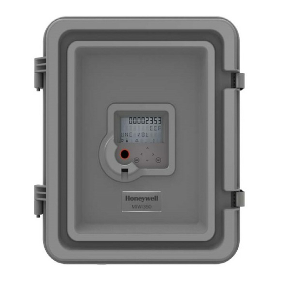
3 Mechanical Assembly and User Interface 3.2 Display Options The MIWI350 device is available with two display options - External and Internal. Power or Communication Box variant is available without display option. Figure 3-4: MIWI350 with External Display Figure 3-5: MIWI350 with Internal Display... -
Page 17: Hmi User Interface
3 Mechanical Assembly and User Interface 3.2.1 HMI User Interface MIWI350 device includes a ten character, configurable, alphanumeric LCD display with icons to display the status information and alarm conditions. The LCD display can be configured to ON or OFF at different times of day. -
Page 18: Gland Entries
- Use to navigate within the elements of the same subgroup. Refer to the Honeywell EC350 User's Manual for more information on using the HMI User Interface. 3.3 Gland Entries P3 Pressure Transducer (Future) -
Page 19: Electrical Assembly
It can be used to reduce the amount of power required by the modem assembly so that non-rechargeable batteries can be used or even smaller solar panels can be installed. Refer Figure 4-2 for more information. Honeywell | 15... - Page 20 Output C is continuously held “ON”. PULSE: Turns on Modem Power Based on Pulse Width. 300mS -> OFF, 600mS -> ON TO MODEM – WITH MODEM POWER MPC Control from IOB CONTROL FEATURE MODEM POWER INDICATOR LED Figure 4-2: Power Distribution Board Honeywell | 16...
-
Page 21: Power Distribution Board Connections Solar-Input/Ac-Dc Input With Lead Acid Battery Back Up
Sun Saver output is directly connected to modem and external output. Can connect to RV50, CL R100 and Pulse/Level input for MPC function CL R110 (CL R1XX - External input). Honeywell | 17... -
Page 22: Power Distribution Board Jumper Settings For Alkaline Battery Or Dc Input
Connects the regulated input to modem and external output connector. The voltage selected using S1 is reflected on these outputs*. Pulse/Level input for MPC function * IMPORTANT NOTE: Never exceed 9V for Alkaline battery input. The supercap connected cannot work beyond 9V. Honeywell | 18... -
Page 23: Power Distribution Board Output Voltage And Jumper Settings
1-2 1-2 AC-DC/TEC Mini-AT AS PER MSG PULSE 2-3 2-3 Mini-AT AS PER MSG PULSE 4.3 Modem The currently supported modems which can be used with a MIWI350 device include: Honeywell CloudLink R100/R110-M1 Modem Sierra Wireless AirLink® RV50/RV50X Honeywell | 19... -
Page 24: Internal Wiring
Figure 5-1: Electrical Wiring between Power Distribution Board and IO Board 5.2 Power Distribution Board and Modem PULSE CELL CMOS/ UART 40-6167 EXT-GND EXT-PWR BATT Cloud Link Modem/RV50 Modem (Optional) Power Distribution Board Figure 5-2: Electrical Wiring between Power Distribution Board and Modem Honeywell | 20... -
Page 25: Io Board And Modem
PULSE CELL CMOS/ UART EXT-GND EXT-PWR BATT CloudLink Modem IO Board Figure 5-3: Electrical Wiring between IO Board and CloudLink Modem RS232 40-2947-9 RV50 Modem IO Board Figure 5-4: Electrical Wiring between IO Board and RV50 Modem Honeywell | 21... -
Page 26: Battery Installation
3. Connect the battery pack cable (*) to battery charge controller cable. by quarter turning the screw. *40-6169-3 - If you are connecting a 12V 7Ah lead-acid battery *40-6169-2 - If you are connecting a 12V 21Ah lead-acid battery Honeywell | 22... -
Page 27: Dual/Quad Alkaline Battery
2. Carefully insert the battery in the mount bracket. Dual battery pack Quad battery pack 3. Close the battery mount flip 4. Connect the dual/quad battery cable to cover and turn back the screw. power distribution board Honeywell | 23... -
Page 28: Battery Life
6 Battery Installation 6.3 Battery Life MIWI350 with CloudLink R100 (1 call/day) Battery Type Months 7Ah 12V DC SLA 21Ah 12V DC SLA Dual Alkaline Battery pack (12Ah-derated) Quad Alkaline Battery Pack (24Ah-derated) 13.7 MIWI350 with CloudLink R110 (1 call/day) -
Page 29: Reference Drawings
7 Reference Drawings 7 Reference Drawings 7.1 MIWI350 with EC350 or ERX350 7.1.1 Wiring Dual or Quad Battery QUAD 18VDC ALKALINE RECEPTACLE PACK DUAL 18VDC ALKALINE RECEPTACLE PACK Note: The cable color code/pin mapping are for illustration purpose only. Figure 7-1: Electrical Wiring - DUAL/QUAD 18VDC ALKALINE RECEPTACLE PACK... -
Page 30: Wiring Solar Power For Miwi350
7 Reference Drawings 7.1.2 Wiring Solar Power for MIWI350 40-6169-3 40-6169-2 CONNECT CONNECT SOLAR SOLAR PANEL PANEL POWER POWER CONNECTOR CONNECTOR SOLAR POWER with 7Ah BATTERY SOLAR POWER with 21Ah BATTERY Note: The cable color code/pin mapping are for illustration purpose only. -
Page 31: Miwi350 As Power Box
7 Reference Drawings 7.2 MIWI350 as Power Box 7.2.1 Wiring Dual or Quad Battery for MIWIPCB DUAL 18VDC ALKALINE RECEPTACLE PACK QUAD 18VDC ALKALINE RECEPTACLE PACK Note: The cable color code/pin mapping are for illustration purpose only. Figure 7-3: Electrical Wiring - DUAL/QUAD 18VDC ALKALINE RECEPTACLE PACK... -
Page 32: Wiring Solar Power For Miwipcb
Connector from Solar Charge controller 12V 21Ah lead-acid battery Connector from Solar Charge controller External power input junction box 40-6169-1 Connector from Solar Charge controller Power Distribution Board P1 (DC-IN) 40-2342-1 Device Ground/Earthing External power input junction box Honeywell | 28... -
Page 33: Miwi350 As Power Or Communication Box
7 Reference Drawings 7.3 MIWI350 as Power or Communication Box 7.3.1 Barrier Connections 7.3.1.1 With CloudLink Modem DO NOT CONNECT BLACK WIRE OF 40-6184. CUT THE STRIPPED CONDUCTORS AND ADD INSULATION TAPE 22-1350 BLACK 40-6184 WHITE BLACK 40-6167-1 40-6167 40-6182 RS485 CONNECTIONS... - Page 34 NOTE: CUT THE CONDUCTORS AND COVER THE "DO NOT USE" PINS WITH INSULATION TAPE DETAIL J ROUTE THE CABLE THROUGH THE PD BOARD PLATE SLOT AND CONNECT AS SHOWN. SCALE 1.30 : 1 Figure 7-6: Internal Wiring - CloudLink R110 Connections Honeywell | 30...
- Page 35 ROUTE CABLE AS SHOWN. 2X 20-8059 TORQUE 8 TO 10 IN-LB INTERNAL ANTENNA CONNECTION (CLOUDLINK R100) INTERNAL ANTENNA CONNECTION (CLOUDLINK R110) Note: For 'Ready for CloudLink Modem' option, all necessary cables and fasteners will be provided except CloudLink modem. Honeywell | 31...
-
Page 36: With Rv50 Modem
THE ANTENNA CABLE SOLDER JOINT. 51508416-100 (CELLULAR ANTENNA) TIGHTEN ANTENNA FITTING WITH 4 TO 6 IN-LB. 2X 20-8460 20-3827 TORQUE 8 TO 10 IN-LB ADD CABLE TIE TO ANTENNA CABLE THROUGH MODEM MOUNTING PLATE SLOT. INTERNAL ANTENNA CONNECTION Honeywell | 32... -
Page 37: Terminal Block Connections
NOTE: CUT THE CONDUCTORS AND COVER THE "DO NOT USE" PINS WITH INSULATION TAPE CASE CONNECTOR TO TERMINAL BLOCK CONNECTION ROUTE THE CABLE THROUGH THE PD BOARD PLATE SLOT AND CONNECT AS SHOWN. DETAIL P SCALE 1.50 : 1 Figure 7-8: Internal Wiring - CloudLink R100 Connections Honeywell | 33... - Page 38 NOTE: CUT THE CONDUCTORS AND COVER THE "DO NOT USE" PINS WITH INSULATION TAPE DETAIL M ROUTE THE CABLE THROUGH THE PD BOARD PLATE SLOT AND CONNECT AS SHOWN. SCALE 1.30 : 1 Figure 7-9: Internal Wiring - CloudLink R110 Connections Honeywell | 34...
- Page 39 ROUTE CABLE AS SHOWN. 2X 20-8059 TORQUE 8 TO 10 IN-LB INTERNAL ANTENNA CONNECTION (CLOUDLINK R100) INTERNAL ANTENNA CONNECTION (CLOUDLINK R110) Note: For 'Ready for CloudLink Modem' option, all necessary cables and fasteners will be provided except CloudLink modem. Honeywell | 35...
-
Page 40: With Rv50 Modem
THE ANTENNA CABLE SOLDER JOINT. 51508416-100 (CELLULAR ANTENNA) TIGHTEN ANTENNA FITTING WITH 4 TO 6 IN-LB. 2X 20-8460 20-3827 TORQUE 8 TO 10 IN-LB ADD CABLE TIE TO ANTENNA CABLE THROUGH MODEM MOUNTING PLATE SLOT. INTERNAL ANTENNA CONNECTION Honeywell | 36... - Page 41 7 Reference Drawings Note: For 'Ready for RV50' option, all necessary cables and fasteners will be provided except RV50 modem. Honeywell | 37...
-
Page 42: External Connections
Follow the below steps to connect pressure tubing to pressure transducer(s): 1. Insert o-ring on transducer fitting threads and push it till it reaches on the groove on case. 2. Insert the jam nut on transducer and tighten it with dome nut clock-wise. Honeywell | 38... -
Page 43: Configuration Software
9 Configuration Software 9 Configuration Software User can use Honeywell MasterLink software application to configure and deploy a MIWI350 device. MasterLink can be used to configure MIWI350 as: EC350/ERX350 Device Cellular Modem (CLR100/CLR110/RV50 Modem) EC350/ERX350 and Cellular Modem as an Integrated Device To learn more about MasterLink, EC350/ERX350, or CloudLink, refer to their respective user guides available on the Honeywell Process Website. -
Page 44: Orderable Kits
10 Orderable Kits 10 Orderable Kits Description Part# METER CASE & DOOR EXT DISP ASSY MIWI350 22-3116-1-KIT METER CASE & DOOR INT DISP ASSY MIWI350 22-3116-2-KIT REMOTE CASE & DOOR EXT DISP ASSY MIWI350 22-3116-3-KIT REMOTE CASE & DOOR INT DISP ASSY MIWI350... - Page 45 10 Orderable Kits Description Part# CL4G BRACKET MIWI350 22-3150-1-KIT RV50 BRACKET MIWI350 22-3150-2-KIT REMOTE BRACKET MIWI350 22-3159-KIT U-BOLT GUILL 2 7/16 OD 2 IN 20-9141-KIT-2 U-BOLT GUILL 3 11/16 OD 3 IN 20-9142-KIT-2 U-BOLT GUILL 4 11/16 OD 20-9140-KIT PORTABLE BRACKET MIWI350...
- Page 46 Notes For more information: To learn more about Honeywell's Smart Gas Metering Solutions, visit MI-TAC-Support@Honeywell.com | www.honeywellprocess.com or contact your Honeywell Process Solutions representative. Honeywell Process Solutions 1280 Kemper Meadow Drive, Cincinnati, OH 45240 855 251-7065 – United States & Canada | 302 669-4253 – Outside the United States FD-610 | Version 2.01 | July 2019...
Need help?
Do you have a question about the MIWI350 and is the answer not in the manual?
Questions and answers
I need the cable that allows me to program this instrument and i cannot figure out what it is called or where to order it