Table of Contents
Advertisement
Quick Links
Advertisement
Table of Contents

Related Manuals for Kane 425

Summary of Contents for Kane 425
- Page 1 KANE425 Flue Gas Analyser Kane International Ltd Kane House, Swallowfield Welwyn Garden City Hertfordshire, AL7 1JG Tel: +44 (0) 1707 375550 Fax: +44 (0) 1707 393277 E-mail: sales@kane.co.uk www.kane.co.uk Stock No: 18366 October 2006 © Kane International Ltd...
-
Page 2: Table Of Contents
CONTENTS Page No: KANE425 Overview ANALYSER LAYOUT & FEATURES BATTERIES 2. BEFORE USING THE ANALYSER EVERY TIME FRESH AIR PURGE STATUS DISPLAY 3. USING THE ANALYSER AND ITS FOUR BUTTONS 10-12 4. USING THE ANALYSER 13-18 COMBUSTION TESTS PRESSURE TEST TIGHTNESS TESTING DIFFERENTIAL TEMPERATURE ROOM CO TESTING... - Page 3 12. ELECTROMAGNETIC COMPATIBILITY APPENDIX 1 – MAIN PARAMETERS 31-33 KANE425 manual Page 3...
-
Page 4: Kane425 Overview
KANE425 Overview The KANE425 Combustion Analyser measures O CO, differential temperature and differential pressure. It calculates CO , CO/CO ratio, losses, combustion efficiency (Nett, Gross or Condensing) & excess air. The KANE425 Combustion Analyser can measure carbon monoxide levels in ambient air - useful when a CO Alarm is triggered. -
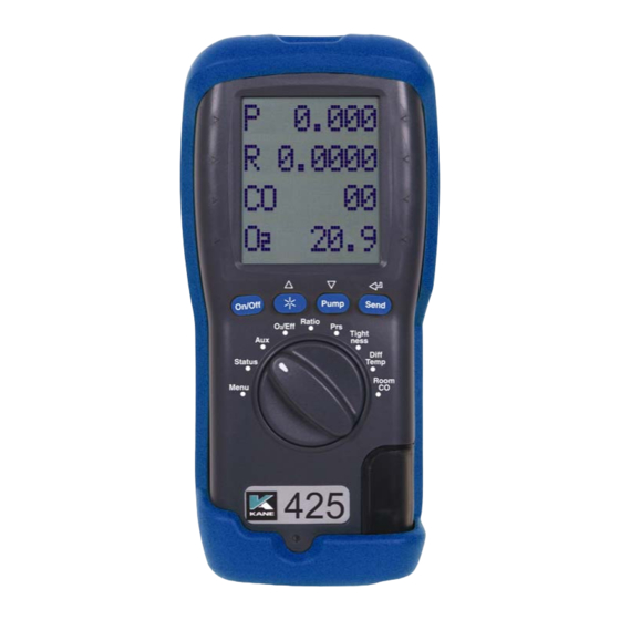
Page 5: Analyser Layout & Features
ANALYSER LAYOUT & FEATURES Torchlight and infra-red emitter Socket for gas leak detector Menu controls Scroll up/down Function buttons Enter Particle Filter Rotary Switch Battery Compartment (behind rubber sleeve) Water Trap “Battery Charging” indicator Flue Gas Inlet Temp and pressure connections KANE425 manual Page 5... - Page 6 KANE425 manual Page 6...
-
Page 7: Batteries
1. BATTERIES Battery Type This analyser has been designed for use with disposable alkaline batteries or rechargeable Nickel Metal Hydride (NiMH) batteries. No other battery types are recommended. WARNING The battery charger unit must only be used when NiMH batteries are fitted. Replacing Batteries Turn over the analyser, remove its’... -
Page 8: Before Using The Analyser Every Time
BEFORE USING THE ANALYSER EVERY TIME: Check the water trap is empty and the particle filter is not dirty: To empty water trap, carefully pull out the rubber drain plug and re-plug once it is empty. To change the particle filter, remove the analyser’s protective rubber sleeve, slide the water trap unit from the analyser, remove the particle filter from its’... - Page 9 SAFETY WARNING This analyser extracts combustion gases that may be toxic in relatively low concentrations. These gases are exhausted from the back of the instrument. This analyser must only be used in well-ventilated locations by trained and competent persons after due consideration of all the potential hazards. KANE425 manual Page 9...
-
Page 10: Using The Analyser And Its Four Buttons
3. USING THE FOUR FUNCTION BUTTONS: Switching Press button to switch the unit ON . This must be done ON the in fresh air to ensure that the analyser auto calibrates its’ Analyser sensors properly. When switched on, the analyser beeps twice and briefly displays battery %, fuel and pressure units. - Page 11 Backlight & Press to switch the display's backlight and torchlight on Torchlight and off. NOTE: Use of the backlight/torchlight increases the current drain on the batteries Switching The analyser normally operates with the pump on. Press PUMP on / to switch the pump off and on. When the pump is switched off “---PO--"...
- Page 12 Storing a set Press and hold for approx. 2+ seconds. of readings The top line briefly display the log number. Note: This STORE function is inhibited in normal operation if the pump is switched off. The function buttons below the symbols Using used to navigate through the menu when the rotary switch is set to MENU –...
-
Page 13: Using The Analyser
USING THE ANALYSER: 4.1 COMBUSTION TESTS: Insert the tip of the flue probe into the centre of the flue. The readings will stabilise within 60 seconds assuming the boiler conditions are stable (see Measuring Flue Gases – Section 7). The rotary switch can be used to display the following information: RATIO Display NAT GAS →... - Page 14 Hold for 2+ seconds to log a full combustion report. AUX display 20.9 The default AUX (auxillary) display is → shown including Oxygen, Carbon Monoxide, current time & battery status. The AUX display can be customised via MENU / SCREEN / AUX to change the 15:04:11 parameters on lines 1, 2, 3 and 4.
-
Page 15: Pressure Test
4.2 PRESSURE TEST Select “Prs”. The pump stops automatically. Press to auto-zero the pressure sensor. Using the black connectors and manometer hose, connect to P1 for single pressure or P1 and P2 for differential pressure. PRS display PRESSURE Defaults to smoothing off on start-up. Can →... -
Page 16: Tightness Testing
4.3 LET-BY & TIGHTNESS TESTING Select “Tightness”. The pump stops automatically. Press to auto-zero the pressure sensor. Connect from the test point to P1 using a black connector and manometer hose. The display shows “LET BY?”. Use to select YES or NO. If YES is selected set the let-by pressure then press to start the let-by test. - Page 17 When stabilisation is complete press to start the tightness test: TIGHTN’S 20.01 → Pressure at start of tightness test 20.01 → Real time pressure reading TIME Tightness default time is 2 minutes. Can → be changed via “Menu”. When complete the display will show: The tightness test is automatically stored in the →...
-
Page 18: Differential Temperature
4.4 DIFFERENTIAL TEMPERATURE Select “Diff Temp” to measure flow, return and differential temperatures DIFF TEMP display TEMP Pump stops automatically when dial is → moved to Diff Temp 60.4 Use the T1 connection for the flow → temperature sensor 55.2 Use the T2 connection for the return →... -
Page 19: Room Co Testing
4.5 ROOM CO TESTING Select “Room CO” for CO investigations. Press to start the 15 minute duration room CO test. ROOM CO display ROOM When complete the room CO test is → automatically stored in the memory → Real time CO reading (ppm) TEST Test 00 = initial reading →... -
Page 20: Kane425 Printouts
4.6 KANE425 PRINTOUTS KANE425 manual Page 20... -
Page 21: Using The Menu
USING THE MENU Select “Menu” on the rotary switch and navigate using the function buttons: = Scroll up = Scroll down = Enter MAIN SUB MENU OPTIONS / COMMENTS MENU NAT GAS, L OIL, PROPANE, BUTANE, LPG, SETUP SET FUEL PELLETS (wood) EfC = condensing boilers EfN = nett efficiency, EfG = gross efficiency,... - Page 22 MAIN SUB MENU OPTIONS / COMMENTS MENU Stored combustion tests: REPORT COMB’N VIEW, DEL ALL, EXIT Stored pressure tests: PRESSURE VIEW, DEL ALL, EXIT Stored tightness tests: TIGHTN’S VIEW, DEL ALL, EXIT Stored differential temperature tests: TEMP VIEW, DEL ALL, EXIT Stored room CO tests: ROOM CO VIEW, DEL ALL, EXIT...
-
Page 23: Using The Kane425 As A Thermometer Or
6. USING THE KANE425 AS A THERMOMETER & PRESSURE METER With the KANE425 switched off, press and hold down the button and after MANO_MOD is displayed then press and release . Release on top line. The KANE425 will now operate as a fixed display thermometer/pressure meter with the pump off and inhibited. -
Page 24: Measuring Flue Gases
7. MEASURING FLUE GASES After the countdown is finished and the analyser is correctly set up, put its’ flue probe into the appliance’s sampling point. The tip of the probe should be at the centre of the flue. Use the flue probe’s depth stop cone to set the position. With balanced flues, make sure the probe is positioned far enough into the flue so no air can ‘back flush’... -
Page 25: Analyser Problem Solving
ANALYSER PROBLEM SOLVING If any problems are not solved with these solutions, contact us or an authorized repair center. Fault symptom Causes / Solutions • Oxygen too high • Air leaking into probe, tubing, water trap, connectors or internal to analyser. •... - Page 26 Fault symptom Causes / Solutions • Analyser just continually • Turn dial back to MENU and press ENTER beeps • BAT only shows 65 with • This is not a problem and is to be expected as fully charged NiMH NiMH batteries only deliver 1.25 V per cell batteries fitted whereas Alkalines deliver 1.5 V per cell.
-
Page 27: Analyser Annual Recalibration And Service
Welwyn Garden City in Hertfordshire (Tel: 01707-375550), the primary service centre for non-UK customers. By sending your analyser back to Kane for an annual fixed price service (check www.kane.co.uk for details) you have the opportunity to extend the warranty on your analyser to 5 years. -
Page 28: Analyser Specification
10. ANALYSER SPECIFICATION (NOTE MAY BE SUBJECT TO CHANGE) Parameter Range Resolution Accuracy Temp Measurement Flue Temperature 0-600 +2.0 +0.3% reading Inlet Temperature 0-50 +1.0 (Internal sensor) +0.3% reading Inlet Temperature 0-600 +2.0 (External sensor) +0.3% reading Gas Measurement Oxygen 0-21% 0.1% +0.2%... - Page 29 220v charger, for NiMH batteries only Chargers (optional) 12v in vehicle charger, for NiMH batteries only Dimensions Weight: 0.8kg handset with boot Handset: 200 x 45 x 90mm Probe: 300mm long including handle. 6mm diameter x 240mm long stainless steel shaft with 3m long neoprene hose.
- Page 30 If not acceptable, adjust the analyser’s position to minimize interference or switch off, if possible, the offending equipment during your test. At the time of writing this manual (August 2005) Kane International Ltd are not aware of any field based situation where such interference has occurred and this advice is only given to satisfy the requirements of the Directive.
- Page 31 Appendix 1 - Main Parameter: Here are the legends used and what they mean: Oxygen reading in percentage (%) Carbon Monoxide reading displayed in ppm (parts per million). ‘- - -’ is displayed if there is a fault with the CO sensor or the instrument has not set to zero correctly, switch off instrument and try again.
- Page 32 X - AIR : Excess air calculated from the measured oxygen and type of fuel used. Displays reading during a combustion test. ‘-O>-’ is displayed while in fresh air. CO/CO CO/CO Ratio: measured CO (ppm) divided by calculated CO (%) x 10,000. PRS: Pressure reading, either single point or differential Displays the Battery power available in %...
- Page 33 SYMBOLS used on the display Pressure CO/CO λ Excess Air Loss %: 100% minus loss % = efficiency % Flue Temperature Inlet Temperature ∆T Nett Temperature Gross efficiency Nett efficiency Condensing efficiency - PO - Pump off -O>- Oxygen greater than 18% so calculation is disabled -OC- Open circuit temperature input Number of days left before recalibration is due...
Need help?
Do you have a question about the 425 and is the answer not in the manual?
Questions and answers