Table of Contents
Advertisement
Advertisement
Table of Contents

Summary of Contents for brent ie
- Page 1 Approved 220-240V AC...
-
Page 2: Table Of Contents
Your New Potter's Wheel ......................3 Important Safety Information ....................4 General Information........................5 Potter's Wheels Chart ........................5 brent® ie and ie-x Potter’s Wheels Leg Installation ............6 Using Your New Wheel .........................6 Install thhe Splash Pan ..................7 How to Operate the Pedal ................7 Caring for Your Wheel ...........................8... -
Page 3: Your New Potter's Wheel
Follow up with a call to the delivering carrier, making an appointment for the inspection. At this time notify AMACO/brent as to the extent of the damage and you will be informed upon the procedures necessary for filing a claim with the freight company. -
Page 4: Important Safety Information
Then turn off power, unplug power the power indicator light is off. Then unplug cord from outlet, and call brent® Repair for the wheel from its power source. assistance. DO take care with long hair, jewelry, and DO NOT remove the control box and panel loose fitting clothing. -
Page 5: General Information
All of these shape clay into its final form. The Brent potter’s components help make Brent pottery wheels the wheel is wrapped in a vacuum formed HDP sheet most dependable wheel on the market. -
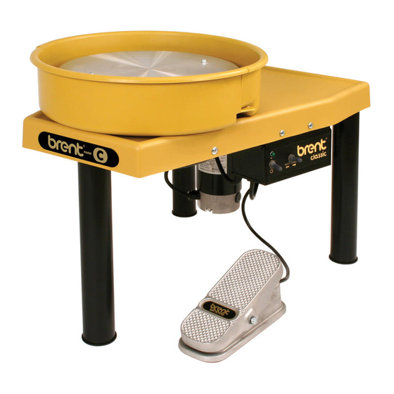
Page 6: Brent® Ie And Ie-X Potter's Wheels Leg Installation
BRENT® IE AND IE-X POTTER’S WHEELS LEG INSTALLATION SHIPPED IN Once you have carefully removed your wheel from the carton, you will find it is shipped in its TABLE-TOP table-top configuration. It comes equipped with CONFIGURATION a 9-foot cord for versatility. -
Page 7: Install Thhe Splash Pan
[ On ] enough, see Troubleshooting on pages 15-17. All wheels except the ie model are reversible. If you wish to reverse the direction, tip the foot pedal toward you in the “OFF” position. When the wheel stops, move the FWD/REV toggle switch to either Forward or Reverse. -
Page 8: Caring For Your Wheel
Store foot pedal on wheel table when not from your brent® wheel. The recommended operating and storage in use. In addition, when mopping studio temperatures is 50-90° F, with a relative floors, foot pedals should be placed on the humidity of less than 60%. -
Page 9: Models: B, C, Cxc, Ex, And #16
MAINTENANCE: STANDARD BELT REPLACEMENT MODELS: B, C, CXC, EX, and #16 Turn wheel off and unplug from the power Locate the belt guard on the bottom of the outlet. Raise the front of the pottery wheel wheel. Use a 7/16" wrench to remove the until the wheel rests on its back legs. -
Page 10: Models: Ie, Ie-R, And Ie-X
2. MODELS: IE, IE-R, and IE-X Turn wheel off and unplug from the power Locate the belt guard panel on the bottom outlet. - Page 11 MAINTENANCE: STANDARD BELT REPLACEMENT MODELS: IE, IE-R, and IE-X (continued) Install new belt by fitting the new belt over Lay one half of the grooved side of the belt the smaller motor pulley first. on the large pulley and start turning the belt and pulley at the same time to “roll”...
-
Page 12: Maintenance: Slide Adjustment
MAINTENANCE: SLIDE ADJUSTMENT MODEL: If there is side play in the wheel or the slides are too tight for ease of height adjustment, No. 16 troubleshoot the problem by first removing the acorn nuts. Lock Nut Set Screw Using the allen wrench and the open-end wrench, hold the set screw in place and loosen the lock nuts. -
Page 13: Maintenance: Wheel Motor Brush Replacement
4 hours per day, 5 days per week for choose the correct brushes for your wheel. MOTORS 5 years. Please contact AMACO/brent FIRST Your replacement brush may come from when your brushes need replacing. Please email AMACO/brent or your local distributor. -
Page 14: Slow Blow Fuse Replacement And Information
B, C, CXC, EX, and #16 REPLACING The slow blow fuse is located near the power switch on the side of the ie series wheels. Push THE SLOW and turn the cap labeled “fuse” to remove. The BLOW FUSE OF cap should come out easily with the slow blow fuse attached. -
Page 15: Troubleshooting
SWITCH POSITIONS: Reverse / Neutral / Forward WHEN POWER Disconnect from the power supply. IS ON Check the fuse and replace if blown. (see page 14) If there is power to the control box and the fuse if fine, please call brent repair for assistance. 800-999-5456... - Page 16 Adjust the guards until rubbing stops. (not applicable for ie models) Tighten bolts. If problem persists, please call brent® Repair for assistance. FOOT PEDAL IS Use a ½” size wrench to tighten or loosen the nut on the side of the foot pedal, as needed.
- Page 17 TROUBLESHOOTING (continued) WHEEL HEAD “HI” Adjustment “LO” Adjustment (Red Disc) (Blue Disc) ROTATES TOO FAST OR TOO SLOW Turn foot pedal over and remove the bottom plastic cover from the pedal. Locate the red disc, this is the “HI” speed adjustment. Using a small standard screwdriver, rotate the red disc clockwise to increase the speed, or counter- clockwise to decrease the speed.
-
Page 18: Parts Diagrams
PARTS DIAGRAM MODELS: B, C, CXC, EX, and #16 Match circled numbers on this page to item numbers on pages 19-20 for part description. brentwheels.com... -
Page 19: Parts Lists
PARTS LIST MODELS: ITEM # QTY. PART # DESCRIPTION 32331K for Models B, 16 B, C, CXC, 32333M for C, CXC & EX Models Plasti-Bat 22135X Bat Pin EX, and #16 Item 2 & 3 sold as set Bat Pin Wing Nut 22012M for B, 16 22017T for C, CXC &... - Page 20 PARTS LIST MODELS: ITEM # QTY. PART # DESCRIPTION Used for Manufacturing Only Motor Mounting Bolt Retainer B, C, CXC, 22306M Motor Mounting Bushing 1/4 Fender Washer Motor Mounting Fender Wsher EX, and #16 1/4 Lock Washer Motor Mounting Lock Washer (continued) 1/4-20 Hex Nut Motor Mounting Hex Nut...
- Page 21 PARTS DIAGRAM MODELS: IE, IE-R, and IE-X Match circled numbers on this page to item numbers on page 22 for part description. 800-999-5456...
- Page 22 PARTS LIST MODELS: ITEM # QTY. PART # DESCRIPTION 32331K for IE & IE-R Models IE, IE-R, and IE-X 32333M for IE-X Models Plasti-Bat 22135X Bat Pin Item 2 & 3 sold as set Bat Pin Wing Nut 22012M for IE & IE-R Models...
-
Page 23: Warranty Information
Models B, C, CXC, EX, 16 Models ie, ie-r, ie-x REPAIR If you have a problem with your brent® wheel within the warranty period, please do the following: INSTRUCTIONS Call AMACO/brent technical support, serial number of the wheel being repaired must accompany the defective parts for the warranty to 800-999-5456 or email technicalsupport@amaco. -
Page 24: Wheel Accessories
BRENT® WHEEL ACCESSORIES BOOTIES WORKSTATION Set of three Leg risers to raise Attaches to rear legs of brent® your wheel 2" or 4" (5.08 or wheels. Holds tools and other 10.16cm). Product No. 22785E supplies while throwing. Height adjustable. Product No. 22878N...
Need help?
Do you have a question about the ie and is the answer not in the manual?
Questions and answers