Advertisement
Centrometal d.o.o. - Glavna 12, 40306 Macinec, Croatia, tel: +385 40 372 600, fax: +385 40 372 61 1
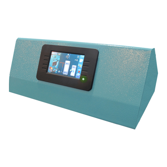
Technical manual
THE DIGITAL BOILER CONTROLLER - USER
READY
THE FIRST COMMISSIONING MUST BE CARRIED OUT BY AN AUTHORIZED
PERSON, OTHERWISE THE PRODUCT WARRANTY IS NOT VALID!
Cm-Pelet set_Touch 14-90 kW
TURPS- 07/2018-ENG Software version v1.23f
HEATING TECHNIQUE
120°C
30%
80°C
1700
60°C
15k
0%
70°C
55°C
50°C
Book 2/2
Advertisement
Table of Contents

Related Manuals for Centrometal Cm Pelet-set Touch 14

Summary of Contents for Centrometal Cm Pelet-set Touch 14
- Page 1 HEATING TECHNIQUE Centrometal d.o.o. - Glavna 12, 40306 Macinec, Croatia, tel: +385 40 372 600, fax: +385 40 372 61 1 Technical manual THE DIGITAL BOILER CONTROLLER - USER READY 120°C 80°C 1700 60°C 70°C 55°C 50°C THE FIRST COMMISSIONING MUST BE CARRIED OUT BY AN AUTHORIZED...
- Page 2 The controller THE CONTROLLER Boiler controller components used by a user: Touchscreen with bicolour LED Safety thermostat UTP cable connector Main switch (0/1) switches the boiler on / off Technical manual - THE DIGITAL BOILER CONTROLLER Cm-Pelet set_Touch 14-90 kW...
-
Page 3: Switching On / Display
Switching on / Display SWITCHING ON / DISPLAY After switching the main switch on, the language selection and software version will appear on the screen. You can choose between different languages. To select the preferred language press a flag on display. The possibility of online boiler monitoring and online boiler operation management... -
Page 4: The Main Menu
The main menu, symbols THE MAIN MENU The main menu is used to select a preferred submenu. To enter into a certain menu press an icon on the screen. To switch between the ''Main menu'' and ''Boiler working display'' press the ''VIEW SELECTION'' button. - Page 5 Symbols SYMBOLS Simboli: Boiler type display: EKO-CKB P + 1 - Boiler temperature Cm Pelet-set_Touch EKO-CK P + EKO-CKB P + 2 - Fuel level * 14-50 Cm Pelet-set_Touch Cm Pelet-set_Touch + recirculation 3 - Transporter is working 14-90 kw 14-50 built in boiler 4 - Photocell...
- Page 6 Symbols SYMBOLS View button / Drop-down menu Room thermostat (all existing elements of automatic / remote boiler start are enabled) Next to the room thermostat symbol bright blue circle (the room thermostat has requested for operating the pump, the pump All elements of automatic / remote boiler does not work if you have not met all the conditions for its operation,...
- Page 7 Symbols, The parameters adjusting Option "Freeze guard" is enabled "Freeze guard" triggered one of the pumps. Burner start is disabled in drop down menu due to ''freezing guard'', freezing protection system works without possibility for burner to work until the boiler is cooled down to minimum temperature . PP-2 Since freezing guard is enabled, burner is started from the OFF phase.
- Page 8 The parameters adjusting THE PARAMETERS ADJUSTING There are 4 different menu types for adjusting the parameters: A - this menu is used to set the parameters that have numerical values (°C, RPM, time...) example: adjust the burner fan rpm, adjusting the boiler temp. etc... B - this menu is used to set parameters that must be selected (marked) to be enabled and there can be multiple selected (enabled) items NOTE: some enabled options disable another one (they can't be enabled at the same time)
- Page 9 The parameters adjusting methods (examples) THE PARAMETERS ADJUSTING METHODS (examples) 1 -parameter you are adjusting 2 - value adjustment box 3 - set value 4 - value type 5 - info button (displays factory, min. and max. values) 6 - resets the current value to the factory value 1 - parameter you are adjusting 2 - value adjustment box 3 - selected option (only one option can be selected)
-
Page 10: Important Notes
Burner start and stop procedur / Switching off the controller BURNER START PROCEDURE (START IS ENABLED) The ways to activate ''start is enabled'' of the burner (burner goes from the OFF phase to the A0 phase (burner starts) or to the S7-3 waiting phase (STANDBY)): - manual activation by pressing the ON/OFF button - activation by schedule (if enabled) - activation by WiFi or CM GSM module (additional equipment) (if it is enabled in drop-down menu and in "Work... -
Page 11: Maintenance
Maintenance 1.0. MAINTENANCE NOTE: Burner cleaning option is not a replacement for manual burner and burner grate cleaning. Burner cleaning must be carried out regulary, according to the technical manual. 1.1. CLEANING THE BURNER Under "CLEANING" menu are two options: Cleaning: this option is used to start the burner fan on the set RPMs to clean the burner grate (note: depending of the pellets quality grate will be more or less clean. - Page 12 Maintenance 1.1.2. BURNER FAN This option is used to adjust burner fan RPMs during cleaning procedure. Possible adjustment: - Factory adjustment: 3000 rpm - Minimal adjustment value: 500 rpm - Maximal adjustment value: 3000 rpm Technical manual - THE DIGITAL BOILER CONTROLLER Cm-Pelet set_Touch 14-90 kW...
- Page 13 Temperature 2.0. TEMPERATURE Temperature menu shows only items applicable to the set configuration. In next section of the manual all avalible configurations and schemes are listed. Availible temperature settings will be described at every individual configuration and scheme in "CONFIGURATIONS" section of this manual.
- Page 14 Schedule 3.0. SCHEDULE This option is used to set a working time of the burner, DHW tank heating, DHW recirculation pump and to change daytime and night time temperature of the first and the second heating circuit. NOTE: This manual shows the screen with the largest possible number of the basic boiler controller devices where schedule is available.
- Page 15 Schedule 1 - current table you are adjusting (table 1 / table 2 / table 3) 2 - day of the week 3 - green - burner start (on) red - burner stop (off) Press the box to adjust the time You can adjust 3 start and stop during 1 day You can copy/paste from one day to another by pressing the "day box"...
- Page 16 Schedule 3.4. SCHEDULE – 1st heating circuit This option is used for adjusting periods when room temperature is maintained. ’’Day temperature’’/’’Night temperature’’ or ’’Table’’ where switching from ’’Day temperature’’ to ’’Night temperature’’ is defined. Possible adjustment: - Factory: Day temperature - Day temperature, Night temperature, Table NOTE: It is possible to adjust one table with different settings.
-
Page 17: Operation Mode
History, Operation mode 4.0. HISTORY This option is used to see the history of the occured "ERRORS" and "WARNINGS» This option is used to see the history of the occured "ERRORS". 1 - error code 2 - description of the error 3 - time and error of operation phase Errors codes are marked with the letter ’’E’’. -
Page 18: Forced Shutdown
Operation mode 5.1. FORCED SHUTDOWN This option is used to forced shut down of the burner in any working stage. Before pressing the "FORCED SHUTDOWN" you must switch off the burner on the ’’ON/OFF’’ switch and confimt ’’STOP’’ action on the main display. - Page 19 Operation mode Case 1. 3–way mixing valve with actuator is 100% closed. OPENING DIRECTION Case 2. 3–way mixing valve with actuator is 100% open. CLOSING DIRECTION Case 3. 4–way mixing valve with actuator is 100% closed. OPENING DIRECTION Installation flow Installation backflow Boiler...
- Page 20 Operation mode 5.3. PELLET TRANSPORTER NOTE: If the transporter is empty, it must be filled before the burner is started. Filling feeder screw: This option is used to initially filling of the transporter. It can also be used if the transporter is emptyed. We recommend that you start the procedure and wait for the process to complete to make sure the transporter is full (20 min.).
- Page 21 Operation mode 5.5. SAVE/LOAD This option is used to save parameters, load / load service parameters and delete saved parameters. SAVE - save current settings LOAD - load saved setting LOAD SERVICE - load setting autorized serviceman saved DELETE - delete saved settings You can save multiple setting under different names and you can load and delete saved setting.
-
Page 22: Standard Equipment
Operation mode 5.6. STANDARD EQUIPMENT This option is used for view (adjusting) standard equipment of Cm Pelet-set_Touch. Options: - sensors - it is only possible to view the type of sensor (PT1000 – factory or NTC 5K) - photocell - it is only possible to preview the photocell settings - 1st circuit / 2nd circuit - the user settings of the heating circuits can be adjusted - DHW- DHW can be set (on / off) and if recirculation is switch on can be set also "Recirculation operation time"... - Page 23 Operation mode 5.6.3.1 - 5.6.4.2 1. CIRCUIT / 2. CIRCUIT It's possible to view all enabled mixing heating circuits (set temperatures, measured temperatures, heating type, working of the pumps etc...). To enter this view press button and then If there are more than 2 mixing heating circuits enabled you can switch view betwen them with buttons.
- Page 24 Operation mode SETTING PARAMETERS FOR EACH HEATING CIRCUIT Regulation can control up to two mixing heating circuits. They must be enabled and set under "INSTALLATION" menu. To make adjustment of each circuits go to the "OPERATION" menu then "STANDARD EQUIPMENT" menu. Possible selection: Factory: ON Option: ON, OFF...
-
Page 25: Additional Equipment
Operation mode 5.7. ADDITIONAL EQUIPMENT This option is used to view the setting / setting of additional equipment that is not in the basic delivery (for most of the equipment the setting lowers on / off and detailed adjustment is performed by the authorized service person. - Page 26 Operation mode 5.7.3. INTERNET SUPERVISION This option is used to connect regulation to the internet trough Cm Wifi-box via WiFi network. Cm WiFi-box is additional equipment and is not part of standard delivery. This option is used to enable/disable Cm WiFi-box and set its parameters. NOTE: view in this menu depends of enabled additional equipment.
- Page 27 Operation mode 5.8.1. FREEZE GUARD Possible selection: Factory: OFF Options: OFF, ON While Freeze guard option is enabled, controller monitors minimum set temperature of each sensor in boiler and equipment attached to controller and, in case that Toutside option is enabled, controller also monitors minimum outside temperature. If temperature drops below set value, controller starts pumps and the boiler if needed.
-
Page 28: Work Mode
Operation mode 5.9. WORK MODE This option enables to set working mode Possible selection: - Factory: Heating+DHW (unless the basic equipment doesn't have any heating circuit) - Options: Heating+DHW, AUTO DHW<>Heat. + DHW, DHW Heating+DHW - this mode is possible if there are both heating circuits and DHW, the heating and DHW tank are controlled according to set conditions. - Page 29 Operation mode, Display This option is used to set time for burner shut down. In case of continuous burner working for this time, burner will shut down (in this process it will clean the grate, with burner fan or air cleaning if it’s installed). After burner shutdown process, burner will start again and this counter will be reset.
- Page 30 Display, Info, Correction - Show timers - this option allows a customer to have the timer of each working phase displayed in the main screen. This option makes it easier to monitor working phases of the burner and other components. - Date &...
-
Page 31: Chimney Sweeper
Chimney sweeper 10. CHIMNEY SWEEPER This option is used to enable and set "CHIMNEY SWEEPER MODE» Options: - Chimney sweeper - it can be enabled or disabled "Chimney Sweeper" mode - Power -it can be set burner power for "Chimney Sweeper" mode - Minimum boiler temerature - it can be set the minimum boiler temperature for "CS"... - Page 32 Installation, Burner working stages 12. BURNER WORKING STAGES Burner working stage OFF - burner doesn’t work (OFF - burner will not start) A0 - burner start - only burner fan is working A1 - start of start up safety time measuring, start of igniter working A2 - start of transporter working (initial filling) A3 -...
- Page 33 Heating configuration (markings on the display) 13. HEATING CONFIGURATION (markings on the display) CONFIGURATION MARKINGS IN GENERAL: XYZ Marking description on the individual positions: X _ _ - the mark on the first position indicates the mode of the boiler connection on the heating installation (return line safety): A - marks the boiler connection with the ACCUMULATION TANK via the 3 way thermostatic valve (return line safety 60°C)
- Page 34 Heating configuration (markings on the display) Example 4: Configuration H10 - boiler connected with 4-WAY MIXING VALVE WITH ACTUATOR (backflow protection), DHW tank and there is a possibility of controlling one or two direct central heating circuits (if one or more CM2K modules with two heating circuits / DHW are not installed).
- Page 35 Heating configuration (markings on the display) 13.1. Configuration A-0-0 EKO-CK P + Cm Pelet-set_Touch Temperatures: Tboiler: 80°C (80-90°C) dTboiler: 10°C (5-15°C) Tbuf: 80°C (70-80°C) dTbuf: 10°C (5-30°C) dTbuf-off: 5°C (3-50°C) 13.2. Configuration A-0-1 EKO-CK P + Cm Pelet-set_Touch Temperatures: Tboiler: 80°C (80-90°C) Tbuf min.: 20°C (5-85°C) 1.
- Page 36 Heating configuration (markings on the display) 13.4. Configuration A-1-0 EKO-CK P + Cm Pelet-set_Touch Temperatures: Tboiler: 80°C (80-90°C) Tdhw: 50°C (10-70°C) dTboiler: 10°C (5-15°C) dTdhw: 5°C (5-50°C) Tbuf: 80°C (70-80°C) Tbuf min.: 20°C (5-85°C) dTbuf: 10°C (5-30°C) dTbuf-off: 5°C (3-50°C) 13.5.
- Page 37 Heating configuration (markings on the display) 13.7. Configuration A-2-0 EKO-CK P + Cm Pelet-set_Touch Temperatures: Tboiler: 80°C (80-90°C) Tdhw: 50°C (10-70°C) dTboiler: 10°C (5-15°C) dTdhw: 5°C (5-50°C) Tbuf: 80°C (70-80°C) Tbuf min.: 20°C (5-85°C) dTbuf: 10°C (5-30°C) dTbuf-off: 5°C (3-50°C) 13.8.
- Page 38 Heating configuration (markings on the display) 13.10. Configuration A-7-0 EKO-CKB P + Cm Pelet-set_Touch Temperatures: Tdhw: Tboiler: Tbuf: 80°C (70-80°C) - Mode: - Heating+DHW: Tdhw=Tboiler=80°C - Mode: -> Heating+DHW: 80°C (80-90°C) dTbuf: 10°C (5-30°C) - DHW: Tdhw=Tboiler=70°C dTbuf-off: 5°C (3-50°C) ->...
- Page 39 Heating configuration (markings on the display) 13.13. Configuration A-8-0 EKO-CKB P + Cm Pelet-set_Touch Temperatures: Tboiler: Tdhw: Tbuf: 80°C (70-80°C) - Mode: -> Heating+DHW: 80°C (80-90°C) - Mode: - Heating+DHW: Tdhw=Tboiler=80°C dTbuf: 10°C (5-30°C) -> DHW: 70°C (70-80°C) - DHW: Tdhw=Tboiler=70°C dTbuf-off: 10°C (3-50°C) dTboiler: dTdhw:...
- Page 40 Heating configuration (markings on the display) 13.16. Configuration B-0-0 EKO-CK P + Cm Pelet-set_Touch Temperatures: Tboiler: 80°C (80-90°C) dTboiler: 10°C (5-15°C) Tbuf: 80°C (70-80°C) dTbuf: 10°C (5-30°C) dTbuf-off: 5°C (3-50°C) 13.17. Configuration B-0-1 EKO-CK P + Cm Pelet-set_Touch Temperatures: Tboiler: 80°C (80-90°C) Tbuf min.: 20°C (5-85°C) 1.
- Page 41 Heating configuration (markings on the display) 13.19. Configuration B-1-1 EKO-CK P + Cm Pelet-set_Touch Temperatures: Tboiler: 80°C (80-90°C) Tdhw: 50°C (10-70°C) 1. Circuit: dTboiler: 10°C (5-15°C) dTdhw: 5°C (5-50°C) Const. temp. day: 60°C (20-90°C) Tbuf: 80°C (70-80°C) Tbuf min.: 20°C (5-85°C) Const.
- Page 42 Heating configuration (markings on the display) 13.22. Configuration B-7-0 EKO-CKB P + Cm Pelet-set_Touch Temperatures: Tdhw: Tboiler: Tbuf: 80°C (70-80°C) - Mode: -> Heating+DHW: 80°C (80-90°C) - Mode: - Heating+DHW: Tdhw=Tboiler=80°C dTbuf: 10°C (5-30°C) - DHW: Tdhw=Tboiler=70°C -> DHW: 70°C (70-80°C) dTbuf-off: 10°C (3-50°C) dTboiler: dTdhw:...
- Page 43 Heating configuration (markings on the display) 13.25. Configuration B-8-1 EKO-CK P + Cm Pelet-set_Touch Temperatures: Tdhw: Tbuf: 80°C (70-80°C) Circuit 1: Tboiler: - Mode: -> Heating+DHW: 80°C (80-90°C) - Mode: - Heating+DHW: Tdhw=Tboiler=80°C dTbuf: 10°C (5-30°C) Const. temp. day: 60°C (20-90°C) ->...
- Page 44 Heating configuration (markings on the display) 13.28. Configuration C-0-2 EKO-CK P + Cm Pelet-set_Touch Temperatures: Tboiler: 80°C (70-90°C) 1. Circuit, 2. Circuit: dTboiler: 10°C (5-15°C) Const. temp. day: 60°C (20-90°C) Const. temp. night: 60°C (20-90°C) Day room temp.: 20°C (5-30°C) Night room temp.: 20°C (5-30°C) 13.29.
- Page 45 Heating configuration (markings on the display) 13.31. Configuration C-1-2 EKO-CK P + Cm Pelet-set_Touch Temperatures: Tboiler: 80°C (70-90°C) 1. Circuit, 2. Circuit: dTboiler: 10°C (5-15°C) Const. temp. day: 60°C (20-90°C) Tdhw: 50°C (10-70°C) Const. temp. night: 60°C (20-90°C) dTdhw: 5°C (5-50°C) Day room temp.: 20°C (5-30°C) Night room temp.: 20°C (5-30°C) 13.32.
- Page 46 Heating configuration (markings on the display) 13.34. Configuration C-2-2 EKO-CK P + Cm Pelet-set_Touch 1. Circuit, 2. Circuit: Temperatures: Tboiler: 80°C (70-90°C) Const. temp. day: 60°C (20-90°C) dTboiler: 10°C (5-15°C) Const. temp. night: 60°C (20-90°C) Tdhw: 50°C (10-70°C) Day room temp.: 20°C (5-30°C) dTdhw: 5°C (5-50°C) Night room temp.: 20°C (5-30°C) 13.35.
- Page 47 Heating configuration (markings on the display) 13.37. Configuration C-7-2 EKO-CKB P + Cm Pelet-set_Touch Temperatures: 1. Circuit, 2. Circuit: Tdhw: Tboiler: Const. temp. day: 60°C (20-90°C) - Mode: -> Heating+DHW: 80°C (70-90°C) - Mode: - Heating+DHW: Tdhw=Tboiler=80°C Const. temp. night: 60°C (20-90°C) ->...
- Page 48 Heating configuration (markings on the display) 13.40. Configuration C-8-2 EKO-CKB P + Cm Pelet-set_Touch Temperatures: 1. Circuit, 2. Circuit: Tdhw: Tboiler: Const. temp. day: 60°C (20-90°C) - Mode: -> Heating+DHW: 80°C (70-90°C) - Mode: - Heating+DHW: Tdhw=Tboiler=80°C Const. temp. night: 60°C (20-90°C) ->...
- Page 49 Heating configuration (markings on the display) 13.43. Configuration D-1-0 EKO-CK P + Cm Pelet-set_Touch Temperatures: Tboiler: 80°C (70-90°C) dTboiler: 10°C (5-15°C) Tdhw: 50°C (10-70°C) dTdhw: 5°C (5-50°C) 13.44. Configuration D-1-1 EKO-CK P + Cm Pelet-set_Touch Temperatures: Tboiler: 80°C (70-90°C) 1. Circuit: dTboiler: 10°C (5-15°C) Const.
- Page 50 Heating configuration (markings on the display) 13.46. Configuration D-2-1 EKO-CK P + Cm Pelet-set_Touch Temperatures: Tboiler: 80°C (70-90°C) 1. Circuit: dTboiler: 10°C (5-15°C) Const. temp. day: 60°C (20-90°C) Const. temp. night: 60°C (20-90°C) Tdhw: 50°C (10-70°C) dTdhw: 5°C (5-50°C) Day room temp.: 20°C (5-30°C) Night room temp.: 20°C (5-30°C) 13.47.
- Page 51 Heating configuration (markings on the display) 13.49. Configuration D-8-0 EKO-CKB P + Cm Pelet-set_Touch Temperatures: Tdhw: Tboiler: - Mode: -> Heating+DHW: 80°C (70-90°C) - Mode: - Heating+DHW: Tdhw=Tboiler=80°C -> DHW: 70°C (70-80°C) - DHW: Tdhw=Tboiler=70°C dTboiler: dTdhw: - Mode: - Mode: - Heating+DHW: 10°C (5-15°C) - Heating+DHW: 15°C (10-40°C) - DHW: 10°C (5-10°C)
- Page 52 Heating configuration (markings on the display) 13.52. Configuration E-0-1 EKO-CK P + Cm Pelet-set_Touch 1. Circuit: Temperatures: Tboiler: 80°C (75-90°C) Const. temp. day: 60°C (20-90°C) dTboiler: 10°C (5-15°C) Const. temp. night: 60°C (20-90°C) Tcro: 75°C (70-80°C) Day room temp.: 20°C (5-30°C) Night room temp.: 20°C (5-30°C) 13.53.
- Page 53 Heating configuration (markings on the display) 13.55. Configuration E-1-1 EKO-CK P + Cm Pelet-set_Touch 1. Circuit: Temperatures: Tboiler: 80°C (75-90°C) Const. temp. day: 60°C (20-90°C) dTboiler: 10°C (5-15°C) Const. temp. night: 60°C (20-90°C) Tcro: 75°C (70-80°C) Day room temp.: 20°C (5-30°C) Tdhw: 50°C (10-73°C) dTdhw: 5°C (5-50°C) Night room temp.: 20°C (5-30°C)
- Page 54 Heating configuration (markings on the display) 13.58. Configuration E-2-1 EKO-CK P + Cm Pelet-set_Touch 1. Circuit: Temperatures: Tboiler: 80°C (75-90°C) Const. temp. day: 60°C (20-90°C) dTboiler: 10°C (5-15°C) Const. temp. night: 60°C (20-90°C) Tcro: 75°C (70-80°C) Day room temp.: 20°C (5-30°C) Tdhw: 50°C (10-73°C) dTdhw: 5°C (5-50°C) Night room temp.: 20°C (5-30°C)
- Page 55 Heating configuration (markings on the display) 13.61. Configuration E-7-1 EKO-CKB P + Cm Pelet-set_Touch Temperatures: Tdhw: Tboiler: Tcro: 75°C (70-80°C) - Mode: -> Heating+DHW: 80°C (75-90°C) - Mode: - Heating+DHW: Tdhw=Tboiler=80°C Circuit 1: -> DHW: 70°C (75-80°C) - DHW: Tdhw=Tboiler=70°C Const.
- Page 56 Heating configuration (markings on the display) 13.64. Configuration E-8-1 EKO-CKB P + Cm Pelet-set_Touch Temperatures: Tdhw: Tboiler: Tcro: 75°C (70-80°C) - Mode: -> Heating+DHW: 80°C (75-90°C) - Mode: - Heating+DHW: Tdhw=Tboiler=80°C Circuit 1: -> DHW: 70°C (75-80°C) - DHW: Tdhw=Tboiler=70°C Const.
- Page 57 Heating configuration (markings on the display) 13.67. Configuration F-0-1 EKO-CK P + Cm Pelet-set_Touch Temperatures: Tboiler: 80°C (75-90°C) Circuit 1: dTboiler: 10°C (5-15°C) Const. temp. day: 60°C (20-90°C) Tcro: 75°C (70-80°C) Const. temp. night: 60°C (20-90°C) Day room temp.: 20°C (5-30°C) Night room temp.: 20°C (5-30°C) 13.68.
- Page 58 Heating configuration (markings on the display) 13.70. Configuration F-2-0 EKO-CK P + Cm Pelet-set_Touch Temperatures: Tboiler: 80°C (75-90°C) dTboiler: 10°C (5-15°C) Tcro: 75°C (70-80°C) Tdhw: 50°C (10-73°C) dTdhw: 5°C (5-50°C) 13.71. Configuration F-2-1 EKO-CK P + Cm Pelet-set_Touch Temperatures: Tboiler: 80°C (75-90°C) Circuit 1: dTboiler: 10°C (5-15°C) Const.
- Page 59 Heating configuration (markings on the display) 13.73. Configuration F-7-1 EKO-CKB P + Cm Pelet-set_Touch Temperatures: Tboiler: Tdhw: Tcro: 75°C (70-80°C) Circuit 1: - Mode: -> Heating+DHW: 80°C (75-90°C) - Mode: - Heating+DHW: Tdhw=Tboiler=80°C Const. temp. day: 60°C (20-90°C) -> DHW: 70°C (75-80°C) - DHW: Tdhw=Tboiler=70°C Const.
- Page 60 Heating configuration (markings on the display) 13.76. Configuration H-0-0 EKO CK P Temperatures: Tboiler: 80°C (70-90°C) dTboiler: 10°C (5-15°C) 13.76.1. Configuration H-0-0 *EKO-CK P + Cm Pelet-set_Touch Temperatures: Tboiler: 80°C (70-90°C) dTboiler: 10°C (5-15°C) *DIRECT HEATING CIRCUITS WITH PUMPS *EKO-CK P + Cm Pelet-set_Touch 13.76.2.
- Page 61 Heating configuration (markings on the display) 13.77. Configuration H-0-1 EKO-CK P + Cm Pelet-set_Touch Temperatures: Tboiler: 80°C (70-90°C) Circuit 1: dTboiler: 10°C (5-15°C) Const. temp. day: 60°C (20-90°C) Const. temp. night: 60°C (20-90°C) Day room temp.: 20°C (5-30°C) Night room temp.: 20°C (5-30°C) 13.78.
- Page 62 Heating configuration (markings on the display) 13.78.2 Configuration H-1-0 *EKO-CK P + Cm Pelet-set_Touch Temperatures: Tboiler: 80°C (70-90°C) dTboiler: 10°C (5-15°C) Tdhw: 50°C (10-70°C) dTdhw: 5°C (5-50°C) *DIRECT HEATING CIRCUITS WITHOUT PUMPS 13.79. Configuration H-1-1 EKO-CK P + Cm Pelet-set_Touch Temperatures: Tboiler: 80°C (70-90°C) Circuit 1: dTboiler: 10°C (5-15°C)
- Page 63 Heating configuration (markings on the display) 13.80.1 Configuration H-2-0 *EKO-CK P + Cm Pelet-set_Touch Temperatures: Tboiler: 80°C (70-90°C) dTboiler: 10°C (5-15°C) Tdhw: 50°C (10-70°C) dTdhw: 5°C (5-50°C) *DIRECT HEATING CIRCUITS WITH PUMPS 13.80.2 Configuration H-2-0 *EKO-CK P + Cm Pelet-set_Touch Temperatures: Tboiler: 80°C (70-90°C) dTboiler: 10°C (5-15°C) Tdhw: 50°C (10-70°C)
- Page 64 Heating configuration (markings on the display) 13.82. Configuration H-7-0 EKO-CKB P + Cm Pelet-set_Touch - Heating+DHW: Tdhw=Tboiler=80°C Temperatures: Tboiler: -> Heating+DHW: 80°C (70-90°C) Tdhw: - Mode: - DHW: Tdhw=Tboiler=70°C - Mode: -> DHW: 70°C (70-80°C) - Heating+DHW: 15°C (10-40°C) dTboiler: dTdhw: - Heating+DHW: 10°C (5-15°C) - DHW: 15 (10-40°C)
- Page 65 Heating configuration (markings on the display) 13.83. Configuration H-7-1 EKO-CKB P + Cm Pelet-set_Touch Temperatures: Circuit 1: -> Heating+DHW: 80°C (70-90°C) Tdhw: - Heating+DHW: Tdhw=Tboiler=80°C Tboiler: Const. temp. day: 60°C (20-90°C) - DHW: Tdhw=Tboiler=70°C - Mode: -> DHW: 70°C (70-80°C) - Mode: Const.
- Page 66 Heating configuration (markings on the display) 13.84.2. Configuration H-8-0 *EKO-CKB P + Cm Pelet-set_Touch Tdhw: - Heating+DHW: Tdhw=Tboiler=80°C Temperatures: Tboiler: -> Heating+DHW: 80°C (70-90°C) - DHW: Tdhw=Tboiler=70°C - Mode: -> DHW: 70°C (70-80°C) - Mode: dTboiler: dTdhw: - Heating+DHW: 10°C (5-15°C) - Heating+DHW: 15°C (10-40°C) - Mode: - Mode:...
- Page 67 Heating configuration (markings on the display) 13.87. Configuration I-0-1 EKO-CK P + Cm Pelet-set_Touch Tbuf min.: 20°C (5-85°C) Temperatures: Tboiler: 80°C (80-90°C) Circuit 1: dTboiler: 10°C (5-15°C) Const. temp. day: 60°C (20-90°C) Tbuf: 80°C (70-80°C) Const. temp. night: 60°C (20-90°C) dTbuf: 10°C (5-30°C) Day room temp.: 20°C (5-30°C) dTbuf-off: 5°C (3-50°C)
- Page 68 Heating configuration (markings on the display) 13.90. Configuration I-2-0 EKO-CK P + Cm Pelet-set_Touch Tdhw: 50°C (10-70°C) Temperatures: Tboiler: 80°C (80-90°C) Circuit 1: dTdhw: 5°C (5-50°C) dTboiler: 10°C (5-15°C) Const. temp. day: 60°C (20-90°C) Tbuf: 80°C (70-80°C) Const. temp. night: 60°C (20-90°C) dTbuf: 10°C (5-30°C) Day room temp.: 20°C (5-30°C) dTbuf-off: 5°C (3-50°C)
- Page 69 Heating configuration (markings on the display) 13.93. Configuration I-7-1 EKO-CKB P + Cm Pelet-set_Touch Temperatures: Tboiler: Tdhw: Tbuf: 80°C (70-80°C) Circuit 1: -> Heating+DHW: 80°C (80-90°C) dTbuf: 10°C (5-30°C) - Mode: - Mode: - Heating+DHW: Tdhw=Tboiler=80°C Const. temp. day: 60°C (20-90°C) ->...
- Page 70 Heating configuration (markings on the display) 13.96. Configuration J-0-0 EKO-CK P + Cm Pelet-set_Touch Temperatures: Tboiler: 80°C (70-90°C) dTboiler: 10°C (5-15°C) 13.97. Configuration J-0-1 EKO-CK P + Cm Pelet-set_Touch Temperatures: Tboiler: 80°C (70-90°C) Circuit 1: dTboiler: 10°C (5-15°C) Const. temp. day: 60°C (20-90°C) Const.
- Page 71 Heating configuration (markings on the display) 13.99. Configuration J-1-1 EKO-CK P + Cm Pelet-set_Touch Temperatures: Tboiler: 80°C (70-90°C) Circuit 1: dTboiler: 10°C (5-15°C) Const. temp. day: 60°C (20-90°C) Tdhw: 50°C (10-70°C) Const. temp. night: 60°C (20-90°C) dTdhw: 5°C (5-50°C) Day room temp.: 20°C (5-30°C) Night room temp.: 20°C (5-30°C) 13.100.
- Page 72 Heating configuration (markings on the display) 13.102. Configuration J-7-0 EKO-CKB P + Cm Pelet-set_Touch -> Heating+DHW: 80°C (70-90°C) Tdhw: - Heating+DHW: Tdhw=Tboiler=80°C Temperatures: Tboiler: - DHW: Tdhw=Tboiler=70°C - Mode: -> DHW: 70°C (70-80°C) - Mode: dTboiler: dTdhw: - Heating+DHW: 10°C (5-15°C) - Heating+DHW: 15°C (10-40°C) - Mode: - Mode:...
- Page 73 Heating configuration (markings on the display) 13.105. Configuration J-8-1 EKO-CKB P + Cm Pelet-set_Touch Temperatures: Tdhw: Tboiler: Circuit 1: - Mode: -> Heating+DHW: 80°C (70-90°C) - Mode: - Heating+DHW: Tdhw=Tboiler=80°C Const. temp. day: 60°C (20-90°C) -> DHW: 70°C (70-80°C) - DHW: Tdhw=Tboiler=70°C Const.
- Page 74 Heating configuration (markings on the display) 13.108. Configuration K-1-0 EKO-CK P + Cm Pelet-set_Touch Temperatures: Tboiler: 80°C (75-90°C) dTboiler: 10°C (5-15°C) Tcro: 75°C (70-80°C) Tdhw: 50°C (10-73°C) dTdhw: 5°C (5-50°C) 13.109. Configuration K-1-1 EKO-CK P + Cm Pelet-set_Touch Temperatures: Tboiler: 80°C (75-90°C) Circuit 1: dTboiler: 10°C (5-15°C) Const.
- Page 75 Heating configuration (markings on the display) 13.111. Configuration K-2-1 EKO-CK P + Cm Pelet-set_Touch Temperatures: Tboiler: 80°C (75-90°C) Circuit 1: dTboiler: 10°C (5-15°C) Const. temp. day: 60°C (20-90°C) Tcro: 75°C (70-80°C) Const. temp. night: 60°C (20-90°C) Tdhw: 50°C (10-73°C) Day room temp.: 20°C (5-30°C) dTdhw: 5°C (5-50°C) Night room temp.: 20°C (5-30°C) 13.112.
- Page 76 Heating configuration (markings on the display) 13.114. Configuration K-8-0 EKO-CKB P + Cm Pelet-set_Touch Tdhw: - Heating+DHW: Tdhw=Tboiler=80°C Temperatures: Tboiler: -> Heating+DHW: 80°C (75-90°C) - DHW: Tdhw=Tboiler=70°C - Mode: -> DHW: 70°C (75-80°C) - Mode: dTboiler: dTdhw: - Heating+DHW: 10°C (5-15°C) - Heating+DHW: 15°C (10-40°C) - Mode: - Mode:...
- Page 77 Heating configuration (markings on the display) Legend: 1 - Boiler EKO-CK P + Cm Pelet set_Touch 2 - Boiler EKO-CKB P + Cm Pelet set_Touch 3 - Safety-vent group (safety valve 2,5 bar) 4 - Closed expansion vessel 5 - Pump P1 6 - Backflow protection: - 3-way mixing valve (min.
- Page 78 Errors 14.0 ERRORS AND WARNINGS 14.1 LIST AND TROUBLESHOOTING OF ERRORS ERROR NAME DESCRIPTION Possible cause: No communication between the PC board and other parts of the boiler. COMMUNICATION Boiler status: Currently goes to OFF mode Troubleshooting: Ensure that all UTP cable connectors ERROR are properly inserted into the connector on the PC board, WITH THE PCB BOARD...
- Page 79 Errors Possible cause: The temperature of the pellet flexible filling tube on the burner is higher than 80° C. Boiler status: Currently goes to OFF mode. Troubleshooting: Possible fulfilling of the burner furnace and flexible tube due to incorrectly adjusted combustion air, HIGH TEMPERATURE incorrectly tuned delivery parameters, inadequate dimensions ON THE INLET TUBE...
- Page 80 Errors Possible cause: Low or fully charged battery. Clock reset at 00:00 and date on 1.1.2000. after switching off or unplugging (or not configured), and at least one switching time (boiler/DHW/recirculation) is switched on. If no switching time is on, this error will not occur, but Warning W2. This burner failure can not be detected by itself, it can only occur if a switch-on time is triggered in the work while we have a W2 warning, in which case the burner goes into the S7 (S7-1) shutdown...
- Page 81 Errors Possible cause: Filling the flexible tube with pellets - variant_1 - when it is in operation reduced pellet supply over a period of time in which it failed to return to the normal filling regime with fulfilling (factory only active on CPPL 90) Boiler status: Currently goes to OFF mode.
- Page 82 Errors Possible cause: Interruption in cables between sensors and control, control contacts, cold connection or defective sensor Boiler status: Departure to the Shutdown phase S7 (S7-1). Troubleshooting: Call an authorized service person to check DEFECT SENSOR the location of the sensor, check for sensor / cable damage, HYDRAULIC check connections at the connectors, check the ohmic CROSSOVER...
- Page 83 Errors Possible cause: Termination in cables between the 2nd heating circuit and control sensor, control contacts, cold connection or defective sensor. Boiler status: The boiler operate normally, 2 circuit stop to operate,switch off the pump. SENSOR 2. CIRCUIT Troubleshooting: Call an authorized service person to check the location of the sensor, check for sensor / cable damage, check connections at the connectors, check the ohmic resistance of the sensor.
- Page 84 Errors Possible cause: Problem with the “code key “ for the power reading: - the key is not placed, not recognized, has a malfunction, we have a cold junction or the key is defective. UNKNOWN BOILER Boiler status: Currently goes to OFF mode. POWER Troubleshooting: Call an authorized serviceman who will check the damage/accuracy of the “...
- Page 85 Errors Possible cause: Defective UTP cable or connections on the controller's PCB boards and CMNET. Boiler status: The boiler operates normally as an COMMUNICATION E100_7 individual boiler ( does not operate in a cascade ). ERROR WITH CMNET Troubleshooting: Call an authorized serviceman who will check all.
- Page 86 Errors Possible cause: Interruption in the cables between the 2 circuit corrector and CM2K, connections on the CM2K, cold junction or defective corrector. Boiler status: The boiler operates normally, the 2 CM2K CORRECTOR CM2K circuit continues to operate as if the corrector is turned off. E104 2.
- Page 87 Errors Possible cause: Interruption in the cables between the 5 circuit sensor and CM2K, connections on the CM2K, cold junction or defective sensor Boiler status: The boiler operates normally, the 5 CM2K SENSOR CM2K circuit stops to operate, stops (turns off) the pump. E109 5.
- Page 88 Errors Possible cause: Interruption in the cables between the 7 circuit corrector and CM2K, connections on the CM2K, cold junction or defective corrector Boiler status: The boiler operates normally, the 7 CM2K CORRECTOR CM2K circuit continues to operate as if the corrector is turned off. E114 7.
- Page 89 Errors Possible cause: The vacuum suction flap is blocked with pellets, dirty or to far away flap sensor. Boiler status: The boiler operates normally. Troubleshooting: Check if the vacuum suction flap is blocked ERROR THE FLAP IS E120 with pellets, check if the flap sensor is dirty with dust, check if NOT CLOSED the flap sensor has a 1 mm distance from the flap, check if the flap sensor responds to the flap (the LED light on the sensor...
- Page 90 Warnings 14.2 LIST AND TROUBLESHOOTING OF WARNINGS Possible cause: It occurs when the controller automatically loads the factory parameters as the data in the data base is faulty/incorrect. Under normal circumstances the warning occurs during the first start after changing the software. Boiler status: The boiler does not operate and it cannot FACTORY continue to operate.
- Page 91 Warnings Possible cause: Power outage or switching off the controller on the main switch (0/1) unrelated in which operation phase the burner is in, including also the phase OFF. Boiler status: The information is written in the warning history IW1-1 POWER OUTAGE and is not announced on the screen.
- Page 92 Malfunction / improper boiler operation 15.0 MALFUNCTION / IPROPER BOILER OPERATION 15.1 SAFETY THERMOSTAT - boiler malfunction On the boiler controller screen following error is announced (E 20 SAFETY THERMOSTAT OR DOOR MICROSWITCH), the boiler behaves itself according to the description of the error E20. If the cause of the E20 error is not the open boiler lower door, bad positioned microswitch along the lower boiler door (the microswitch is not sufficiently pressed when the door is closed), faulty microswitch along the lower boiler door –...
-
Page 93: Electric Scheme
Electric scheme ELECTRIC SCHEME 1/8 Note: - outputs P2 – P5 can be configured as pumps outputs or (as) outputs for additional equipment (air cleaning and fan flap, and it must be selected, in the controller, which output is used for which additional equipment) - if all pump outputs are already in use, and there is also additional equipment, it is necessary to connect an additional electronic plate to the controller or reconnect some of the pumps to the CM2K module Technical manual - THE DIGITAL BOILER CONTROLLER Cm-Pelet set_Touch 14-90 kW... - Page 94 Electric scheme ELECTRIC SCHEME 2/8 Note: - this outputs can be used for heating circuits motor actuators, 3-way mixing valves or 4-way mixing valve in boiler return protection Technical manual - THE DIGITAL BOILER CONTROLLER Cm-Pelet set_Touch 14-90 kW...
- Page 95 Electric scheme ELECTRIC SCHEME 3/8 BURNER2 K EY E X T1 E X T 2 01 0 2 5 V IN Note: - the controller is set, by default, to use PT1000 sensors (if necessary it can be configured to use NTC5K sensors – can be configured by an authorized serviceman only) Technical manual - THE DIGITAL BOILER CONTROLLER Cm-Pelet set_Touch 14-90 kW...
- Page 96 Electric scheme ELECTRIC SCHEME 4/8 Technical manual - THE DIGITAL BOILER CONTROLLER Cm-Pelet set_Touch 14-90 kW...
- Page 97 Electric scheme ELECTRIC SCHEME 5/8 - CPPL 14-50 Technical manual - THE DIGITAL BOILER CONTROLLER Cm-Pelet set_Touch 14-90 kW...
- Page 98 Electric scheme ELECTRIC SCHEME 6/8 - CPPL 90 Technical manual - THE DIGITAL BOILER CONTROLLER Cm-Pelet set_Touch 14-90 kW...
- Page 99 Electric scheme ELECTRIC SCHEME 7/8 - ADDITIONAL EQUIPMENT AND ROOM CORRECTOR WITH 2 WIRES BURNER2 6,5K 6,5K K EY E X T1 E X T 2 01 0 2 5V IN Note: - when connecting room correctors with only 2 wires, posssibility of room temperature correction is lost (any correction must be done on the boiler regulation or trough WEB PORTAL) - regarding the firmware version, on older version resistor 6,5K must be installed between inputs 1 (POS) and 2 (GND) so correction is 0;...
- Page 100 Electric scheme ELECTRIC SCHEME 8/8 -ROOM THERMOSTAT (only direct heating circuit) BURNER2 K E Y E X T1 E X T 2 01 02 5 V IN Technical manual - THE DIGITAL BOILER CONTROLLER Cm-Pelet set_Touch 14-90 kW...
- Page 101 Resistance table TABLE WITH RESISTANCE NTC 5k/25°C TABLE WITH RESISTANCE Pt1000 SENSOR SENSOR (range -20 do +130°C) (range -30 do +400°C) Temperatura (°C) Otpor (W) Temp. (°C) Resist. (W) Temp (°C) Resist.(W) 48.535 1.732 36.465 1.751 27.665 1.770 21.158 1.789 16.325 1.809 12.694...
- Page 102 50°C Centrometal d.o.o. assumes no responsibility for possible inaccuracies in this book originated typographical errors or rewriting, all the pictures and diagrams are principal and it is necessary to adjust each actual situation on the field, in any case the company reserves the right to enter their own products such modifications as considered necessary.
Need help?
Do you have a question about the Cm Pelet-set Touch 14 and is the answer not in the manual?
Questions and answers