Table of Contents
Advertisement
Advertisement
Table of Contents
Troubleshooting

Related Manuals for GSK DA98A


Summary of Contents for GSK DA98A
- Page 1 DA98A AC SERVO DRIVE UNIT User Manual (Version 3.00)
- Page 2 DA98A AC Servo Drive Unit User Manual This user manual describes all items on this DA98A AC servo drive unit in detail. However, it’s impractical to give particular descriptions for all unnecessary and/or unavailable operations on this product due to the content limit of the manual, specific product applications and other causes.
- Page 3 DA98, DA98A, DA98B, DA98D series full digital AC servo drive device, DY3 series compound stepper motor drive device, DF3 series responsive stepper motor drive device, GSK SJT series AC servo motors, CT-L NC slider and so on. The current national standard (and international standard), industry standard, as well as the enterprise standard (or enterprise internal standard) as a supplementary, are completely implemented in GSK production process.
- Page 4 DA98A AC Servo Drive Unit User Manual product and superexcellent service” has made GSK what it is now, and GSK will continue to spare no efforts to consummate this South China CNC industry base and enhance China CNC industry by GSK’s “century enterprise, golden brand”...
-
Page 5: Foreword
This manual gives a full description on the functions and operations for DA98A AC servo drive unit and it will make you to get a full knowledge to use it properly and safely. In addition, this manual also involves some special knowledge and precautions on using. - Page 6 DA98A AC Servo Drive Unit User Manual Pay attention to the following signs when reading this user manual: If operation is incorrect, a dangerous situation may Warning occur, resulting in death or serious injuries. If operation is incorrect, a dangerous situation may...
-
Page 7: Table Of Contents
DA98A AC Servo Drive Unit User Manual CONTENTS FOREWORD ........................... IV WARNINGS ........................... VII CHAPTER 1 OVERVIEW ......................1 1.1 Introduction............................1 1.2 Reception check ..........................2 1.3 Outline ..............................3 CHAPTER 2 INSTALLATION....................6 2.1 Environmental condition ........................6 2.2 Installation of AC servo drive unit..................... -
Page 8: Warnings
DA98A AC Servo Drive Unit User Manual WARNINGS Warning ● Design and manufacturing of the product are not used for the mechanism and system that may cause danger to people. ● Precautions in design and making of the user machinery and system matched with this product should be taken into account to avoid accidents resulted by mal-operation or malfunction of this product. - Page 9 DA98A AC Servo Drive Unit User Manual Connection Warning ● Only qualified personnel can do or check the connection. ● Connection and checking can only be done in 5 minutes after the power supply is cut off. ● The AC servo drive unit and servo motor must be well grounded.
- Page 10 DA98A AC Servo Drive Unit User Manual Troubleshooting Warning ● Do not disconnect the cables and touch the terminal blocks within 5 minutes after power is off because of the residual voltage of the drive unit. ● Personnels undertaking disconnection and maintenance must be qualified with the corresponding knowhow knowledge and capabilities.
-
Page 11: Chapter 1 Overview
DA98A AC servo drive unit (also called full digital AC servo drive unit) is a new generation of full digital AC servo drive unit provided by GSK CNC equipment co,. Ltd. The product has been employed with Digital Signal processor (DSP), Complex Programmable Logic Device (... -
Page 12: Reception Check
Please contact with us or suppliers if there are any questions after receiving goods. 2) Model signification: (1) Model for AC servo drive unit DA98A-10-110SJT-M040D Suited servo motor model ( GSK SJT series) ※ Output power: 2 digits (04,06…23) corresponding to 0.4~2.3KW ※ Series code ※... -
Page 13: Outline
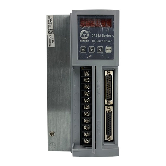
(2) Servo motor model DA98A AC servo drive unit can be matched with many domestic and abroad servo motor models which can be selected by user order. Servo motor models of GSK SJT series are introduced in Chapter 8 of this manual, and other servo motor models information are provided with servo motor delivery. - Page 14 DA98A AC Servo Drive Unit User Manual Fig. 1-1 Outline of AC servo drive unit...
- Page 15 DA98A AC Servo Drive Unit User Manual 2) Outline of servo motor Fig. 1-2 Outline of SJT series servo motor...
-
Page 16: Chapter 2 Installation
DA98A AC Servo Drive Unit User Manual CHAPTER 2 INSTALLATION Note Storage and installation for this unit must be complied to the environmental requirement. Do not put the products into a pile to protect from being damaged or fallen down. - Page 17 DA98A AC Servo Drive Unit User Manual 1) Installation environment (1) Protection The servo drive unit without guard must be installed in a well protected electrical cabinet to prevent corrosive or inflammable gas, liquid, electricity-conductor, metal particls or oil fog from entering it.
- Page 18 DA98A AC Servo Drive Unit User Manual (2) Fixation interval The fixation interval for single drive unit is shown in Fig. 2.3 and intervals for multiple drive units are shown in Fig. 2.4. The interval for actual fixation should be as larger as possible to get a good heat dissipation.
-
Page 19: Servo Motor Installation
The motor must be secured firmly and there should be measures against loose. 1)Installation environment (1) Guard GSK SJT series are not employed with waterproof device, so prevent liquid from splashing onto the motor and oil or water from entering into the motor along its lead wires and shaft. Note Please make a mark in order if waterproof servo motor is needed. -
Page 20: Chapter 3 Wiring
DA98A AC Servo Drive Unit User Manual CHAPTER 3 WIRING Warning ● The system wiring or check can only be done by qualified personnels. ● Wiring and check can only be done in 5 minutes to avoid electric shock after the power supply is cut off. - Page 21 DA98A AC Servo Drive Unit User Manual unit is at fault. (2) Control signal CN1, feedback signal CN2 Wire diameter: it is employed with shield cable, wire diameter ≥0.12mm (AWG24-26) and shield layer should be connected with FG terminal. Wire length: the cable length should be as possible as short, the CN1 cable should be less than 3m, and the feedback signal CN2 cable should be less than 20m.
- Page 22 DA98A AC Servo Drive Unit User Manual Fig. 3.1 Wiring of position control mode...
- Page 23 DA98A AC Servo Drive Unit User Manual Fig. 3.2 Wiring of speed control mode...
-
Page 24: Terminals Function
DA98A AC Servo Drive Unit User Manual 3.2 Terminals function 1) Terminals configuration Fig. 3.3 is the interface terminal configuration of servo drive unit. TB is terminal block; CN1 is DB25 connector assembly,the socket is male type and the plug is female type;... - Page 25 DA98A AC Servo Drive Unit User Manual Output terminals of servo motor must be TB-5 Servo motor output connected correspondingly with U, V, W TB-6 terminals of motor TB-7 TB-8 Standby TB-9 Standby TB-10 Power supply input terminal of control circuit...
- Page 26 DA98A AC Servo Drive Unit User Manual CW drive stop input terminal RSTP ON:CW drive enable RSTP OFF:CW drive stop It is used for mechanical overload. Note 1 CW drive CN1-10 RSTP Type 1 When the switch is put for OFF, the torque in stop CW direction is kept for 0.
- Page 27 DA98A AC Servo Drive Unit User Manual Usually, parameter No.34> parameter No.36. Input terminal of CW torque limit RIL ON:CW torque is limited by parameter No.37. CW torque RIL OFF : CW torque is not limited by CN1-13 Type 1 limit parameter No.37.
-
Page 28: I/O Interface Principle
DA98A AC Servo Drive Unit User Manual 4) Feedback signal terminal CN2 Table 3.3 CN2 input/output terminal of encoder signal Terminal Terminal mark Function Signal name Color Mark Mode CN2-5 CN2-6 Power supply CN2-17 output (+) servo motor photoelectric CN2-18 encoder is employed with +5V power supply;... - Page 29 DA98A AC Servo Drive Unit User Manual AC servo drive unit side COM+ 12~24V 4.7K Fig. 3.4 Type 1 Input interface of switching volume (1) Power suppy is provided by user,DC12~24V,current≥100mA; (2) Note If current polarity is connected reversely, the drive unit will not run.
- Page 30 DA98A AC Servo Drive Unit User Manual AC servo drive unit side PULS+ PULS- SIGN+ SIGN- Fig. 3.7 Type 3 Single terminal drive mode of pulse volume input interface (1) Differential drive mode is recommended to be used to transmit pulse data.
- Page 31 DA98A AC Servo Drive Unit User Manual Table 3.5 Time sequence parameter of pulse input Parameter Differential drive input Single terminal drive input T ck >2μs >5μs >1μs >2.5μs >1μs >2.5μs T rh <0.2μs <0.3μs T rl <0.2μs <0.3μs >1μs >2.5μs...
- Page 32 DA98A AC Servo Drive Unit User Manual Input interface of servo motor photoelectric encoder AC servo drive unit side Motor side AM26LS32 X=A,B,Z,U,V,W Fig. 3.10 Input interface of servo motor photoelectric encoder...
-
Page 33: Chapter 4 Parameters
4.1 Parameter list Values set by factory in Table 4.1 are applicable for the AC servo drive unit matching GSK 110SJT-M020E(2N•m, 3000r/min)motor. The parameters for different motors are not identical. Table 4.1... - Page 34 DA98A AC Servo Drive Unit User Manual Position instruction pulse reverse direction Pulse Positioning completion range 0~30000 ×100 Position out-of-tolerance detection 0~30000 pulse range Position out-of-tolerance error invalid 0.1ms Position instruction smooth filter 0~30000 Drive stop input invalid P,S r/min...
-
Page 35: Parameter Function
DA98A AC Servo Drive Unit User Manual 4.2 Parameter function Table 4.2 Parameter function Parameter Name Function range ① It is used for parameter to be modified by mistake. Usually set this parameter for a required password and then set the parameter to be modified. - Page 36 DA98A AC Servo Drive Unit User Manual Select display state after the AC servo drive unit is powered on. 0:Motor speed display; 1:Current position lower 5-bit display; 2:Current position higher 5-bit display; 3:Position instruction (instruction pulse accumulation ) lower 5-bit display;...
- Page 37 DA98A AC Servo Drive Unit User Manual ① Set the proportional gain of speed loop regulator. ② The bigger the setting value is, and the higher the gain is, the bigger the rigidity is. The parameter value is defined by...
- Page 38 DA98A AC Servo Drive Unit User Manual ① Set frequency division/multiplication (electronic gear) of position instruction pulse. ② In position control mode, various pulse resource can be conveniently matched by parameter No.12, No.13 setting to get a desirable control resolution( i.e. angle/pulse) by user.
- Page 39 DA98A AC Servo Drive Unit User Manual ① It filters the instruction pulse smoothly, which has an exponential acceleration/deceleration. Its value represents the time constant. ② The filter doesn’t lose input pulse, but the instruction lag may occur. ③ The filter is used for: Position instruction 0~30000×0.1...
- Page 40 DA98A AC Servo Drive Unit User Manual ① It is used for displaying the system linear running speed ② conversion numerator linear speed × = linear speed motor speed (r/min) conversion denominato linear speed Conversion ③ The decimal point location of linear speed is defined by the numerator of parameter No.32.
-
Page 41: Correspondance Of Model Code Parameter And Motor
④ If the AC servo drive unit is combined with external position loop, this parameter is set for 0. 4.3 Correspondence of model code parameter and motor Table 4.3 Correspondence of parameter No.1 and GSK SJT series servo motor Parameter №1 Servo motor model and technical parameter Remark 110SJT-M040D,1.0kW,300V, 4.5A,4.0N.m,2500r/min... - Page 42 DA98A AC Servo Drive Unit User Manual 130STZ7.5-2-HM, 2.0kW,300V, 9.5A,3000r/min,2.8×10 kg.m ※ 130STZ10-2-HM, 2.3kW,300V, 9.5A,2500r/min,3.6×10 kg.m ※ 130STZ15-1-HM, 2.1kW,300V, 8A,1500r/min,5.2×10 kg.m ※ 90STZ1-HM, 0.3kW,300V, 2.0A,3000r/min,2.1×10 kg.m 90STZ2-HM, 0.6kW,300V, 3.0A,3000r/min,3.1×10 kg.m 110STZ6-2-HM,1.7kW,300V, 7A,3000r/min,1.29×10 kg.m ※ 130STZ4-1-HM, 0.8kW,300V, 4A,2000r/min,1.6×10 kg.m 130STZ4-2-HM, 1.2kW,300V, 5.5A,3000r/min,1.6×10 kg.m...
- Page 43 The factory set parameters for LIYUAN series servo motor have been backup in the EEPROM area of DA98A AC servo drive unit. When these parameters are to be recovered in DA98A AC servo drive unit, the user should perform backup...
-
Page 44: Alarm And Troubleshooting
DA98A AC Servo Drive Unit User Manual CHAPTER 5 ALARM AND TROUBLESHOOTING Note Personnel undertaking check and maintenance should be qualified with the knowhow knowledge and capability. Do not touch the drive unit and motor within 5 minutes after they are cut off to avoid electric shock and burning. -
Page 45: Alarm Troubleshootings
DA98A AC Servo Drive Unit User Manual Encoder counting error Encoder counting is abnormal. The electrothermal value of the motor exceeds Motor heat overloading the setting value (I t detection). Thermal reset The system is thermally reset. IC4 (EEPROM) is at fault. - Page 46 DA98A AC Servo Drive Unit User Manual ① Reduce the load inertia. ② Change the drive unit The load inertia is too large. and motor by larger power ones. ① Change servo Occuring motor. as motor Encoder zero fault ② Adjust the encoder zero is started by the manufacturer.
- Page 47 DA98A AC Servo Drive Unit User Manual Occuring control Change power supply Circuit board fault servo drive unit. powered on ① Motor U, V, W lead wires are wrongly connected. Connect the wires correctly. ② Lead wires encoder cable are wrongly connected.
- Page 48 DA98A AC Servo Drive Unit User Manual Check Input terminals Drive stop connection and the CCW, CW drive stop power supply of the abnormal are both broken off. input terminals. ① Check mechanical part ① Motor of the load. mechanically The position ②...
- Page 49 DA98A AC Servo Drive Unit User Manual U, V, W of drive unit are short Check the connection. circuit. Grounding is not good. Be grounded correctly. 12 Overcurrent Motor insulation is damaged. Change the motor. Change the AC servo drive AC servo drive unit is damaged.
- Page 50 DA98A AC Servo Drive Unit User Manual Encoder is damaged. Change the motor. Encoder Encoder connection Check the connection. wrong. counting error Grounding is not good. Do right grounding. Occuring Change the AC servo drive Circuit board fault. control power unit.
- Page 51 DA98A AC Servo Drive Unit User Manual ① Encoder UVW phase are damaged. Encoder ② Encoder Z phase is damaged. ①Change the encoder. ③ The cable is inferior. UVW signal ②Check the encoder ④ The cable shielding is not good.
-
Page 52: Chapter 6 Display And Operation
DA98A AC Servo Drive Unit User Manual CHAPTER 6 DISPLAY AND OPERATION 6.1 Keyboard operation The drive unit panel is comprised by 6 LED nixie tube displayer and 4 keys of ↑, ↓, ←, Enter, which is used for displaying system modes and parameters setting etc. And the functions for keys are as followings: ↑... -
Page 53: Monitoring Mode
DA98A AC Servo Drive Unit User Manual 6.2 Monitoring mode Select “dP-” in the first layer and press Enter to enter monitoring mode which includes 21 display modes. Select the desired display mode by ↑, ↓ key, then press Enter to enter display mode. - Page 54 DA98A AC Servo Drive Unit User Manual [Note 7] The absolute position of rotor in a rev means a position the rotor relative to the stator, one rev is one period, and its range is 0~9999. [Note 8] Input terminals are shown as Fig.6.3, output terminals as Fig.6.4, and encoder signal display as Fig.6.5.
-
Page 55: Parameter Setting
DA98A AC Servo Drive Unit User Manual “cn- on”: The main circuit is charged and the servo system is running; [Note 10] The alarm “Err --” displayed means the system is normal and no alarm is issued. 6.3 Parameter setting Note Other parameters can be modified after parameter No.0 is set to its... -
Page 56: Parameter Management
DA98A AC Servo Drive Unit User Manual 6.4 Parameter management If read operation is not performed for the parameter modified, the modified value of the parameter is not saved after power-down and the Note parameter modification is not valid. The parameters management mainly processes memory and EEPROM operation. Select “EE-”... - Page 57 DA98A AC Servo Drive Unit User Manual memory. In this operation parameter writing is not executed and the data in EEPROM parameter area will be read into the memory again when power on. If user want to permanently use the parameters in EEPROM backup area, another parameter write operation is needed.
-
Page 58: Trial Speed Run
DA98A AC Servo Drive Unit User Manual Note It is suggested that the trial speed run or JOG run is done in motor dry run mode in order to avoid the unexpected accident. The AC servo drive unit SON (servo enable) should be valid and CCW, CW stop invalid in trial run. -
Page 59: Chapter 7 Running
DA98A AC Servo Drive Unit User Manual CHAPTER 7 RUNNING Note The drive unit and the motor must be well grounded, and the PE terminal of drive unit must be well connected with the device grounding part. It is suggested that the power supply of drive unit is provided via isolation transformer and power supply filter to get better security and anti-interference capability. - Page 60 DA98A AC Servo Drive Unit User Manual Fig. 7.1 Power supply wiring diagram Time sequence of power on and alarm: Fig. 7.2 Time sequence at power on...
-
Page 61: Trial Run
DA98A AC Servo Drive Unit User Manual Fig. 7.3 Time sequence of alarm 7.2 Trial run 1) Check before running After installation and wiring, check the following items before power on: Make sure the terminal connection of power supply and the input voltage are reliable and right. -
Page 62: Adjustment
DA98A AC Servo Drive Unit User Manual (3) Set control mode (parameter No.4) for JOG mode (for 3). (4) Switch on the main power. (5) If there is no alarm or any abnormality occurring, set servo enable (SON) for ON, and the motor is excited for zero speed. - Page 63 DA98A AC Servo Drive Unit User Manual changed as the load is changed. Generally, the bigger the load inertia is, the smaller the [Speed integral time constant] setting value is. Position control (1) Set proper [Speed proportional gain] and [Speed integral time constant] by the methods above.
- Page 64 DA98A AC Servo Drive Unit User Manual Fig. 7.4 Adjustment block diagram of primary parameters 3) Resolution and electronic gear setting The position resolution (one pulse travel l) is defined by the travel S per rev of the servo △...
- Page 65 DA98A AC Servo Drive Unit User Manual Load inertia multiplier Allowable on-off frequency >100 times/min: acceleration/deceleration time m≤3 60ms or less 60 ~ 100 times/min: acceleration/deceleration m≤5 time 150ms or less < 60 times/min: acceleration/deceleration time m>5 150ms above (2) Effect of the servo motor...
-
Page 66: Chapter 8 Specifications
The AC servo drive unit should be matched with a suited servo motor in user Note order. In this manual the servo motor involved with this drive unit is GSK SJT series motor. Please remark in your order if you want other model servo motors. -
Page 67: Servo Motor Specification
(Refer to outline) 8.2 Servo motor specification 1) Brief Characteristics of GSK SJT series 3-phase AC permanent magnetism synchronous servo motor are as follows: √ Latest rare-earth material employed ensures big output power. √ Good low speed performance of motor with timing ratio>1:10000. - Page 68 DA98A AC Servo Drive Unit User Manual Table 8.3 Encoder connection Mark Pin-out GND A GND is the grounding terminal of the encoder power V . Pin 1 is for protection Remark grounding (shell). 3) SJT series motor specification Table 8.4...
- Page 69 DA98A AC Servo Drive Unit User Manual Rated torque (N·m) Max. torque (N·m) Rated speed 2500 2500 1500 2500 (r/min) Max. speed 3000 3000 2000 3000 (r/min) Moment inertia 1.33×10 1.85×10 2.42×10 2.42×10 (kg·m ) Specification 130SJT—M150B 130SJT—M150D Item Rated power (kW)...
- Page 70 DA98A AC Servo Drive Unit User Manual 5) Motor outline and installation dimensions (1) The outline and installation dimensions of 110SJT series motor are as following: Specification D(mm) N(mm) LB(mm) L(mm) 110SJT—M020E φ19 φ95 156 (207) 211 (262) -0.013 -0.035 110SJT—M040D...
-
Page 71: Isolation Transformer
DA98A AC Servo Drive Unit User Manual Specification D(mm) N(mm) LB(mm) L(mm) 130SJT—M040D φ22 φ110 168 (227) 225 (284) -0.013 -0.035 130SJT—M050D φ22 φ110 168 (227) 225 (284) -0.013 -0.035 130SJT—M060D φ22 φ110 190 (249) 247 (306) -0.013 -0.035 130SJT—M075D φ22... - Page 72 DA98A AC Servo Drive Unit User Manual Outline and installation dimensions for model BS—120...
- Page 73 DA98A AC Servo Drive Unit User Manual Outline and installation dimensions for model BS—200...
- Page 74 DA98A AC Servo Drive Unit User Manual Outline and installation dimensions for model BS—300...
- Page 75 DA98A AC Servo Drive Unit User Manual Outline and installation dimensions for model BD—80...
- Page 76 DA98A AC Servo Drive Unit User Manual Outline and installation dimensions for model BD—120...
-
Page 77: Chapter 9 Order Guide
DA98A AC Servo Drive Unit User Manual CHAPTER 9 ORDER GUIDE 9.1 Capacity selection This servo drive unit capacity is involved with load inertia, load torque, desired positioning precision and max. speed, it is recommended to consider it by the following steps:... -
Page 78: Stop Characteristics
DA98A AC Servo Drive Unit User Manual 9.3 Stop characteristics Lag pulse is defined to a difference value between the instruction pulse and feedback pulse when the servo motor is controlled by pulse strings in position control mode. The difference value... - Page 79 DA98A AC Servo Drive Unit User Manual ZM: gear teeth of lead screw side; L: lead screw pitch Generally, S=I,so the instruction value is equal to the actual one. Max. instruction speed of CNC: ⋅ ≤ δ × F:instruction speed mm/min;...
- Page 80 Add: No.52, 1 . Street, Luochong North Road, Luochongwei, Guangzhou, 510165, China Website: http://www.gsk.com.cn E-mail: gsk@gsk.com.cn Tel: 86-20-81796410/81797922 Fax: 86-20-81993683 All specifications and designs are subject to change without notice. Oct. 2007/Edition 2 Software Version 3.00 Dec. 2007/Printing 2...
Need help?
Do you have a question about the DA98A and is the answer not in the manual?
Questions and answers