Table of Contents
Advertisement
Quick Links
Advertisement
Table of Contents
Troubleshooting

Related Manuals for Newport 1815-C


Summary of Contents for Newport 1815-C
- Page 1 Model 1815-C Optical Power Meter PERATOR ANUAL...
-
Page 3: Warranty
Warranty Newport Corporation warrants this product to be free from defects in material and workmanship for a period of 1 year from the date of shipment. If found to be defective during the warranty period, the product will either be repaired or replaced at Newport’s option. -
Page 4: Ec Declaration Of Conformity
EC DECLARATION OF CONFORMITY Model 1815C We declare that the accompanying product, identified with the " " mark, meets the intent of the Electromagnetic Compatability Directive, 89/336/EEC and Low Voltage Directive 73/23/EEC. Compliance was demonstrated to the following specifications: EN50081-1 EMISSIONS: Radiated and conducted emissions per EN55011, Group 1, Class A EN50082-1 IMMUNITY:... -
Page 5: Table Of Contents
Table of Contents Page Warranty ......................ii EC Declaration of Conformity ................. iii List of Figures ....................vi List of Tables ....................vi Safety Symbols and Terms ................vii General Warnings and Cautions ..............vii Definitions ....................... viii Specifications ....................ix Section 1 –... - Page 6 Section 4 – Test, Maintenance and Troubleshooting Maintenance Procedures ..............14 Performance Verification ..............14 4.2.1 Environmental Conditions ............14 4.2.2 Recommended Test Equipment ..........14 4.2.3 Initial Conditions ................ 15 4.2.4 Verification Procedures ............. 15 Troubleshooting Guide ................ 17 Section 5 –...
- Page 7 List of Figures Figure 1 Model 1815-C Controller and Accessories ......... 1 Figure 2 Model 1815-C Front Panel and Controls ..........4 Figure 3 Model 1815-C Rear Panel and Controls ..........4 Figure 4 Model 1815-C Range Knob..............5 Figure 5 Detector Time Constant Acceleration Adjustment ......
-
Page 8: Safety Symbols And Terms
42VDC or 42V peak AC. Do not exceed 42V RMS between any portion of the Model 1815-C (or any attached detector or probe) and earth ground or a shock hazard will result. -
Page 9: Definitions
Definitions analog-to-digital converter battery option standard coaxial connector type °C degrees Centigrade direct current °F degrees Fahrenheit hertz (cycles per second) current-to-voltage converter kilohertz kΩ kiloOhm milliamp millivolt nanoamp nanofarad nanometer relative humidity root-mean-square serial number µA microamp µs microsecond volt watt viii... -
Page 10: Specifications
6 positions, one per decade of gain <70% RH Noncondensing Operating Environment: 18°C – 28°C (65°F – 82°F) <90% RH Noncondensing Storage Environment: Compatible Detectors: Newport Low-Power Detectors — except 818-F-SL, 818-F-IR Newport High-Power Detectors Electrical Specifications: Range Knob Positions µW µW... - Page 11 1M ohm CAL Factor = 1.00E+0 The maximum measurable input voltage allowed by the 1815-C is 300 mV. Display Noise Floor scales with the calibration factor in the following way: Display Noise Floor = (specified noise floor) × (calibration factor mantissa)
- Page 12 300 mV is the maximum input voltage allowed before the internal electronics saturate. † These limits allow the use of compatible Newport detectors over their calibrated operating ranges.
-
Page 14: System Overview
Section 1 General Information System Overview The Model 1815-C is an accurate low cost optical power meter that provides optical measurement capability from nanowatts to kilowatts. Front panel Range and ZERO functions facilitate use while a wavelength compensation CAL feature insures that NIST/NPL traceable measurements can be performed. -
Page 15: Unpacking And Inspection
The following table describes the accessories and services available for use and Services with the Model 1815-C Optical Power Meter. Refer to Figure 1 for where each accessory fits within the Model 1815-C Optical Power Meter family tree. For more information, please refer to the Newport Catalog. -
Page 16: Section 2 - System Operation
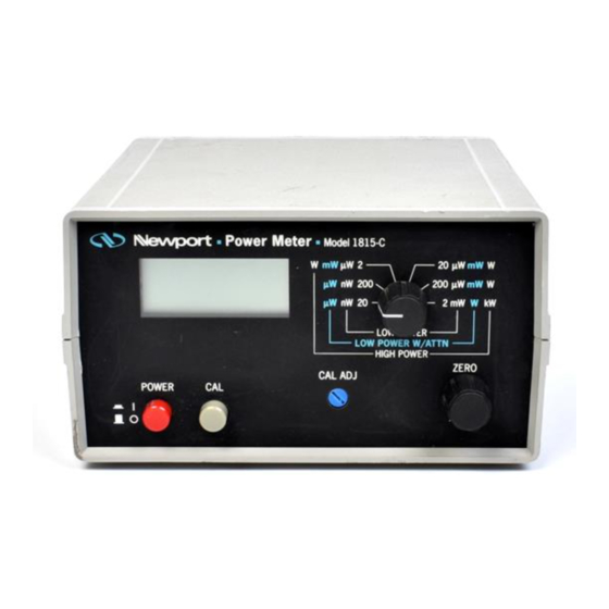
For general operation, only the front panel controls are used. The rear panel controls and settings are used for meter/detector setup. The front and rear panels of the Model 1815-C are shown in Figures 2 and 3 respectively. The following table gives a short description of each Model 1815-C control: Table 2 —... -
Page 17: Range Knob
The Range knob is shown in Figure 4. This knob adjusts the signal gain of the Model 1815-C. The units arrayed around the knob reflect the units of measure- ment when using a particular type of Newport detector. As an example, if a... -
Page 18: Zero Knob
Optical Power Meter. If any operating instructions are not clear, contact Newport Corporation. Using the System The Model 1815-C Optical Power Meter relies on the user to properly install the calibration factor describing the detector at the measurement wavelength in use. In order to assure that accurately calibrated measurements are obtained, please carefully read and follow the instructions regarding Detector Calibration Factor and its entry. -
Page 19: Battery Installation/Replacement
2.4.1. 2.4.3 Detector Connection and Setup Connect the detector to the INPUT BNC found on the rear of the Model 1815-C. You may connect or disconnect any Newport Low-Power, or High-Power detector at any time (even when the meter is on) without damage. -
Page 20: Setting The Detector Calibration Factor
2.4.4 Setting the Detector Calibration Factor The calibration factor tells the Model 1815-C how to account for a detector’s responsivity at the measurement wavelength. Each Newport detector arrives with calibration information. The information will reflect detector responsivities and calibration factors. A calibration factor is calculated from a responsivity by simply taking the inverse of the responsivity and expressing it in scientific notation, i.e. -
Page 21: Detector Acceleration Time Constant
NOTE Accelerator circuit will increase the noise floor level. The Model 1815-C uses an acceleration circuit to electronically shorten the risetime of Newport’s High-Power disk thermopile detectors. This is done when SETUP switch position 4 is set to “1”. A back panel potentiometer, ACCEL ADJ, is used to adjust the time constant of the acceleration circuit to match the time constant of the detector. -
Page 22: Analog Output
2.4.6 Analog Output The Model 1815-C provides a 0 to 2 volt BNC analog output for signal monitor- ing. The signal reflects actual power measured by being equal to the digital display value. Thus, if the digital display indicates 1.560, then the analog... -
Page 23: Section 3 - Principles Of Operation
Power detector families generate. These detector families are based on semiconductor and disk thermopile detectors respectively. A block diagram of signal flow through the Model 1815-C is shown in Figure 6. The actual flow through the diagram depends upon the SETUP switch settings. -
Page 24: Detector Calibration And Accuracy
These dark currents can be zeroed at any moment in time via the Model 1815-C’s ZERO knob. Since dark currents drift with temperature, the ZERO should be adjusted just prior to taking any measurements. The noise or drift in the dark current sets a lower bound on the measurement resolution which can be achieved with any given detector. -
Page 25: Ambient And Stray Light
Remember, if you can see your detector element, then your detector can see the light bouncing off your shirt! Performing Basic Basic measurement techniques for using the Model 1815-C are covered in the Measurements following sections. Also included are methods of background correction and common measurement errors. -
Page 26: Common Measurement Errors
System Accuracy The system measurement accuracy of the Model 1815-C Optical Power Meter is primarily governed by the calibration accuracy of the attached detector. The electronic accuracy of the Model 1815-C exceeds the calibration uncer- tainties of detectors by almost one decade. -
Page 27: Section 4 - Test, Maintenance And Troubleshooting
4.2.1 Environmental Conditions The instrument should be operated with ambient temperature surrounding the Model 1815-C between 18°C and 28°C with a relative humidity of less than 70%. 4.2.2 Recommended Test Equipment Equipment for verifying the performance of the Model 1815-C is listed in Table 7. -
Page 28: Initial Conditions
Figure 7 — Model 1815-C Range Switch Positions a. Verifying current measurement performance: 1. Set the Model 1815-C SETUP DIP bank to: 1, 0, 1, 0 for positions 1, 2, 3 and 4 respectively. 2. Set the Range switch to position 1, the highest gain position. See Figure 7. -
Page 29: Table 8 Model 1815-C Current Calibration Check
0.008 mA b. Verifying voltage measurement performance: 1. Set the Model 1815-C SETUP DIP bank to: 0, 1, 1, 0 for positions 1, 2, 3 and 4 respectively. 2. Set the Range switch to position 3, the highest gain position in the voltage mode. -
Page 30: Troubleshooting Guide
Guide with the power meter so that, to the greatest extent possible, the return of the power meter/detector system to Newport will be unnecessary. For the problems that cannot be resolved with information in this manual, or for other situations that are not covered in this section, please see Section 5 for details on returning your entire system to Newport for service. -
Page 31: Section 5 - Factory Service
1. Instrument model number (On front panel) 2. Instrument serial number (On rear panel) 3. Description of the problem. If the instrument is to be returned to Newport Corporation, you will be given a Return Authorization Number, which you should reference in your shipping documents. -
Page 32: Service Form
Service Form Newport Corporation U.S.A. Office: 949/863-3144 FAX: 949/253-1800 RETURN AUTHORIZATION # Name ____________________________________________________________________________________ ______________________________ Company (Please obtain prior to return of item) ______________________________________________________________________________ Address Date __________________________________________________________________ ________________________________________________________________________________ Country Phone Number __________________________________________________ ________________________________________________________________________________ FAX Number P.O. Number _________________________________________________________________________ _____________________________________________________ Item(s) Being Returned:... - Page 34 1791 Deere Avenue Irvine, CA 92606 (In U.S.): 800-222-6440 Tel: 949-863-3144 Fax: 949-253-1680 Internet: sales@newport.com Visit Newport Online at: www.newport.com P/N 19571-01, Rev. F Newport Corporation, Irvine, California, has IN-03923 (1-00) been certified compliant with ISO 9001 by the British Standards Institution.
Need help?
Do you have a question about the 1815-C and is the answer not in the manual?
Questions and answers