Table of Contents
Advertisement
Hauptsitz und Produktion / Headquarter & Production:
WIWA Wilhelm Wagner GmbH & Co. KG
Gewerbestraße 1 – 3 • 35633 Lahnau, Germany
Tel +49 64 41-6 09-0 • Fax +49 64 41-6 09-50
E-mail: info@wiwa.de • Internet: www.wiwa.de
WIWA Wilhelm Wagner LP
3734A Cook Blvd. • Chesapeake, VA 23323, USA
Tel +1-757-436-2223 • Fax +1-757-436-2103
Tel. (Toll Free) +1-866-661-2139
E-mail: sales@wiwalp.com • Internet: www.wiwa.com
WIWA Taicang Co., Ltd.
Add: No.87 East Suzhou Rd.,
Taicang city, Jiangsu province 215400, P.R.China
Tel: 86-512-5354 8858
Fax: 86-512-5354 8859
Email: info@wiwa-china.com
Translation of the original operation manual
•303_208176_1004_en•ski
User's handbook
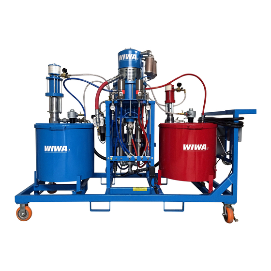
WIWA DUOMIX
Manufacturing-No.: ... ... ... ... ... ... ... ...
Model: 333
8000144
Advertisement
Table of Contents

Related Manuals for wiwa Duomix 333


Summary of Contents for wiwa Duomix 333
- Page 1 Hauptsitz und Produktion / Headquarter & Production: WIWA Wilhelm Wagner GmbH & Co. KG Gewerbestraße 1 – 3 • 35633 Lahnau, Germany Tel +49 64 41-6 09-0 • Fax +49 64 41-6 09-50 E-mail: info@wiwa.de • Internet: www.wiwa.de WIWA Wilhelm Wagner LP 3734A Cook Blvd.
- Page 2 WIWA WILHELM WAGNER GmbH & Co. KG Gewerbestraße 1-3 • 35633 Lahnau Phone: +49 (0)6441 609-0 • Fax: +49 (0)6441 609-50 • E-mail: info@wiwa.de • Internet: www.wiwa.de This operating manual is solely intended for personnel involved in preparation, operation and servicing.
-
Page 3: Table Of Contents
Contents Contents page Preface ........................4 First read, then start Warning instructions 1.2.1 Warning instructions on the unit 1.2.2 Note about the guarantee of the product Note about the user‘s handbook Machine card Safety ........................7 Description of symbols Sources of danger Operating staff and personal protective equipment Protective equipment Handling of the machine and auxiliary material... -
Page 4: Preface
Preface Preface First read, then start Remember that 2K-Units work under extreme pressure and that high levels of spray- ing pressure are created! Never hold your finger or hand in front of the gun and never reach into the spray! ➤... -
Page 5: Warning Instructions
Preface Warning instructions 1.2.1 Warning instructions on the unit Warning signs and symbols which have been placed on the machine are there to inform of possible dangers and must be observed. Warning signs and symbols may not be removed from the machine. Damaged and illegible warning signs and symbols are to be replaced immediately. -
Page 6: Note About The User's Handbook
Preface Danger caused by attachments and spare parts If you use original attachments and original spare parts from Wilhelm Wagner GmbH & Co. KG, the compatibility with our equipment is guaranteed. It is, however, essential that the safety regulations of the attachments and spare parts are observed. You can find these safety regulations in the user’s handbook located with the spare parts lists. -
Page 7: Safety
Safety Safety Description of symbols The signs and symbols used in this manual have the following meaning: NOTE Marks a section of text which is especially relevant to safety. Special attention should be paid to this section and it‘s contents strictly observed! WARNING Marks a situation which could be dangerous. -
Page 8: Sources Of Danger
Safety Sources of danger Always remember, plural component systems operate at very high pressure levels and unauthorized usage could lead to life-threatening injuries. Observe and adhere to all instructions found in the user‘s handbooks for optional acces- sories. Pay close attention to the chapter “Safety” found in the separate user’s manuals. Pay attention to the following notes: Danger when spraying Never point the spray gun* towards yourself, other people or other living creatures! - Page 9 Safety Danger to the unit A change of the mixing ratio may have the consequence of the change of the pres- ➤ sure ratio and a required change of the maximum allowed compressed air pressure. The installed safety valve must be changed. In this case you get from exchangeable nameplate with the new now valid data of the 2K-unit.
-
Page 10: Operating Staff And Personal Protective Equipment
Safety If you use thinner in the material hoses (e.g. for the complete cleaning) all connected ➤ material heaters must be turned off. Complete cleaning may only be done when the unit has cooled. DANGER OF EXPLOSION! Smoking, open flames or any other possible ignition sources are not allowed any- ➤... -
Page 11: Protective Equipment
Safety Protective equipment All units are delivered with the following protective equipment: Safety valve (picture 2.4) The safety valve prevents the maximum admissible entry air pressure from being ex- ceeded. In the event that the fixed maximum entry air pressure setting is surpassed, the safety valve blows open. -
Page 12: Handling Of The Machine And Auxiliary Material
Safety Check list for inspecting the protection features when the unit is in a depressur- ized state Inspect the safety valve leading or seal for damage. ➤ Inspect the safety valve for visible damage. ➤ Inspect the grounding cable for damage. ➤... -
Page 13: Behavior In Case Of Emergency
Safety Behavior in case of emergency Leaks If leaks occur in the system, it must be shut down immediately and the entire system has to be depressurized: Interrupt the compressed air supply with the main tap lock and the pressure regulator. ➤... -
Page 14: About The Machine
About the machine About the machine Use of the machine DUOMIX allows application of environmentally friendly coatings on to surfaces with a minimum of solvent. This 2K-unit has been designed to meet the special requirements (paint to be sprayed, mixing ratio, volumes etc.). The precise dosing is given by the fixed mixing ratio. -
Page 15: Machine Surroundings
About the machine Machine surroundings Emissions It is possible for solvent vapors to occur, depending on the materials used. Therefore, please ensure the workplace is sufficiently ventilated in order to avoid damage to health and property. Always observe the processing information given by the material manufac- turer. -
Page 16: Installation Site
About the machine Installation site DUOMIX can be installed inside or outside of spraying chamber and spray booth. An outside installation is preferable to avoid pollution. Safety measures at installation site: The system must have a fixed position and sufficient space to ensure safe operating. ➤... -
Page 17: Component Description
About the machine Component description 10.1 10 B 10.1 10 A 8 A 8.1 10.2 A 10.2 B 12 A 7.1 A 12 B Translation of the original operation manual •303_208176_1004_en•ski... - Page 18 About the machine Position Description pressure and metering monitor START-button STOP-button switch MANUAL/AUTMATIC air regulator with finest filter precision air regulator stroke counter air maintenance unit air cut-off ball valve air regulator of main pump de-icing modul contact gauge high pressure filter dispensing unit flush pump air regulator of flush pump...
- Page 19 About the machine Remote mixer 13.1 13.2 13.3 Position Description 13.1 lever CIRCULATION 13.2 lever SPRAY 13.3 lever for separate flushing of the A-/ B-sides of the mixer Translation of the original operation manual •303_208176_1004_en•ski...
-
Page 20: Diagram Of The Settings Of The Mixer
About the machine Diagram of the settings of the mixer 3.7.1 Circulate : Illustration of Picture 3.4 the valves Settings on mixer Circulate OPEN Spray CLOSED Flush (A+B) CLOSED 3.7.2 Spraying with manual setting Settings on mixer Circulate CLOSED Spray OPEN Flush CLOSED... -
Page 21: Spraying With Automatic Monitoring
About the machine 3.7.3 Spraying with automatic monitoring Settings on mixer Circulate CLOSED Spray OPEN Flush (A+B) CLOSED 3.7.4 Flushing Settings of the mixer Circulate CLOSED Spray CLOSED Flush (A+B) OPEN Translation of the original operation manual •303_208176_1004_en•ski... -
Page 22: Assembly And Setting Up
Assembly and Setting up Assembly and Setting up Having processing material ready All materials to be sprayed should be marked with information on viscosity, processing temperatures, mixing proportions etc. If this is not the case, please request this data from the relevant material manufacturer. - Page 23 Assembly and Setting up Connect on the mixer Connect the air pressure on the maintenance unit ➤ ➤ ➤ Close the shut-off (pos. 2.1) ball valve on the maintenance unit. ➤ ➤ ➤ Turn back air regulator (pos. 2.2) of the main pump to the left until it eases. ➤...
- Page 24 Assembly and Setting up Check maximum pressure Please check the permissible maximum pressure for the material hose and spray gun*. It must be greater than or equal to the maximum operational pressure for the system, which is shown on the type plate on the high pressure pump or on the machine card. Compare the maximum operating pressure of the safety valve with the information on the machine card or the type plate.
-
Page 25: Commissioning
Commissioning Commissioning To avoid unnecessary work interruption, take absolute care that the containers/drums are not running dry thereby causing the pump to suck air. If this does happen, the system switches off automatically. In this case, bleed the system Base component thoroughly and start again from the beginning. - Page 26 Commissioning Open the shut-off ball valves (pos. 10.2) on the material pump feed lines. ➤ Remove the return hoses (pos. 9) from the filling container and secure them in a ➤ separate open container. Now, turn switch MANUAL/AUTOMATIC (pos. 1.3) on control panel to “MANUAL”. ➤...
- Page 27 Commissioning WARNING! In case the equipment does not switch itself off, turn back the pressure at the air main- tenance unit to 0 bar and DO NOT proceed further with the commissioning! First check the 3/2-way valve for emergency shut-off of the air supply. Exchange defected parts if necessary and start commissioning procedure all over again.
- Page 28 Commissioning Trigger the spray gun* and let the system run dry through it. ➤ When finished lock the spray gun* again. ➤ Turn back the air regulator (pos. 10.1) of the feed pumps to 0 bar. ➤ CAUTION! Turn the air regulator (pos. 2.2) of the main pump to 0 bar. The flush pump has to ➤...
- Page 29 Commissioning Settings on the mixer (Circulate) Turn the lever on the external mixer: ➤ SPRAY (pos. 13.2) to “CLOSED”. ➤ FLUSH (pos. 13.3 A / B) to “CLOSED”. ➤ CIRCULATE (pos. 13.1) to “OPEN”. ➤ Set the air regulator (pos. 10.1) on the feed pumps to approx. 3 - 5 bar. ➤...
- Page 30 Commissioning Increase the air inlet pressure to allow the dispensing unit to overcome the backpres- ➤ sure. Flush until clean material is emitted. ➤ Close the lever of the dispensing unit. ➤ Exchange the containers for clean measuring jugs. ➤ Open the lever on the dispensing unit and fill the desired amount of material.
- Page 31 Commissioning CAUTION! In case the spraying pressure has to be changed, the pressure gauges have to be readjusted as well. If the pointers (black) of the pressure gauge is not moving at all or only insufficiently, the system SHOULD NOT be operated at all. DANGER OF WRONG MIXING RATIOS!!! Now turn the MANUAL/AUTOMATIC switch (pos.
-
Page 32: Operation
Operation Operation Spraying coatings CAUTION! At all times it must be possible to flush components, which were contaminated by mixed material, within the given pot life! Apply the spray gun* safety catch if stopping work even for a few minutes. Disengage the safety and trigger the spray gun* to begin working. -
Page 33: Job Commencement
Operation Job commencement CAUTION! Apply the spray gun* safety catch if stopping work even for a few minutes. Static charges can cause sparks which can itself cause fire and explosions. Due to possible electrostatic charge, DO NOT use narrow neck cans or drums with bung- holes. -
Page 34: Pause In Work And End Of Work
Operation Turn switch MANUAL/AUTOMATIC (pos. 1.3) on the control panel to “MANUAL”. ➤ CAUTION! Settings on the mixer (spray) When you set the switch on the control Turn lever on the external mixer: ➤ panel to „MANUAL“ and SPRAY lever (pos. 13.2) to “OPEN”. “SPRAY”, a timer starts ➤... - Page 35 Operation Task: The work on the unit is going to be interrupted or completely stopped. Flush components, which were contaminated by mixed material within the pot life given by the manufacturer! If you are stopping the work on the machine for a longer time you should follow the instruction listed in the chapter “Complete Cleaning”.
- Page 36 Operation Settings on the mixer (circulate) Turn lever on the external mixer: ➤ SPRAY lever (pos. 13.2) to “CLOSED”. ➤ FLUSH (pos. 13.3 A / B) to “CLOSED”. ➤ CIRCULATE (pos. 13.1) to “OPEN”. ➤ CAUTION! Circulate until the indicators (black) on the contact gauge (pos. 3) are at 0 bar. When shutting down the ➤...
-
Page 37: Material Change
Operation Immension heater (pos. 12): ➤ Turn off the equipment by lowering the temperature on the adjusting knob. and ➤ disconnect it from the power connection. Agitator (pos. 8.1): ➤ Turn down the speed of the agitator by using the regulator (pos. 8.1). ➤... -
Page 38: Complete Cleaning
Complete cleaning Complete cleaning Static charges can cause sparks which can lead to fire and explosions. Due to possible electrostatic charge, DO NOT use narrow neck cans or drums with bung- holes. With metallic containers, take care that the spray gun* is constantly in contact with the container wall. - Page 39 Complete cleaning Empty the material containers (pos. 7 A / B) by spraying the rest of the material into ➤ an empty container or let the system run dry by circulating the material over the return hoses. If the viscosity of the material allows for draining through the drain valve: place empty containers under the drain valves (pos.
- Page 40 Complete cleaning Open the lever of the dispensing unit (pos. 5). ➤ Increase the air inlet pressure to allow the dispensing unit to overcome the backpres- ➤ sure. Flush until clean thinner is emitted. ➤ Close the lever of the dispensing unit. ➤...
- Page 41 Complete cleaning WARNING! Parts of the hand can be crushed or cut while lowering the drum cover onto the container edge. Never hold parts of the body (finger, etc.) in the area of the container edge and drum cover! Make sure that no clothing gets caught in this area or pulled into the container! Let the system run dry.
-
Page 42: Maintenance
Maintenance Maintenance General notes We recommend having the machine checked and inspected once a year by an expert ➤ - customer services). Check level of release agent before every operation and top up if necessary (see ➤ diagram). Maintenance schedule The values listed are only guide values. -
Page 43: Cleaning Of The High-Pressure Filter
Maintenance 8.2.1 Cleaning of the High-Pressure filter (See picture 8.1) Close the low pressure ball valves in front of the material pumps. ➤ Circulate slowly approx. 30 – 60 sec. to empty the high pressure filters. ➤ Set circulation pressure to zero to stop circulation. ➤... -
Page 44: Disturbances During Operation And Trouble-Shooting
Disturbances during operation and trouble-shooting Disturbances during operation and trouble-shoo- ting If you are looking for a remedy of a problem please observe the chapter “Disturbances during operation and trouble-shooting” in the user’s manuals of the optional accessory equipment. Faults Probable Causes Remedies 1. - Page 45 Disturbances during operation and trouble-shooting Faults Probable Causes Remedies 8. Pressure of hardener and base One of the bottom valves of the Check and clean both bottom ➤ ➤ is considerably higher on the base material pumps is defective. valves. upstroke than on the downstroke.
- Page 46 Disturbances during operation and trouble-shooting Faults Probable Causes Remedies 15. When spraying, the air motor runs The air supply line is not sufficient. Change the compressor. ➤ ➤ irregularly. Cross section of air supply line is Enlarge cross section of air supply ➤...
- Page 47 Disturbances during operation and trouble-shooting Faults Probable Causes Remedies 22. The equipment can not be started, Ball valve at the air maintenance Open ball valve at the air mainte- ➤ ➤ although the pressure gauge at unit is closed. nance unit. the air maintenance unit shows The air supply of the control panel Ensure sufficient air supply of the...
- Page 48 Disturbances during operation and trouble-shooting Faults Probable Causes Remedies 30. Hardener or paint leaks from the Packings of the material pump are Replace packings and gaskets. ➤ ➤ intermediate body below the air worn. motor. 31. A fluid heater does not operate. Electrical power supply is cut off.
-
Page 49: Appendix
Appendix 10 Appendix 10.1 Auxiliary materials and special tools Auxiliary material Auxiliary material -Purchase Order No. Release agent (0,5 l)* 0163333 Anti freeze (0,5 l)** 0631387 Pneumatic oil (0,5 l)** 0632579 Securing material (50 ml)*** 0000015 Lubricant (acid-free grease 0,4 kg)*** 0000025 Softener for filling the release agent chamber of the fluid pump for air maintenance unit... -
Page 50: Certificate Of Training And Operation
Appendix 10.2 Certificate of Training and Operation This certificate corresponds to the EU guideline for working substances 85/655/EWG, Paragraph II, Article 7. The owner of the following machine has trained the operating personnel. …………………………………………………………………………………………… (Make, Model, Year of Construction, Order Number) The training was conducted by the following designated person: ……………………………………………………………………..
Need help?
Do you have a question about the Duomix 333 and is the answer not in the manual?
Questions and answers