Table of Contents
Advertisement
Quick Links
Advertisement
Table of Contents

Related Manuals for Newport Oriel VeraSol LSS-7120


Summary of Contents for Newport Oriel VeraSol LSS-7120
- Page 1 User’s Guide LED Solar Simulator VeraSol 700482_A March 2019...
-
Page 3: Table Of Contents
T able of Contents Safety Information and the Manual ................1 General Safety Considerations .................. 1 Safety Symbols ......................2 Safety Marking Symbols .................... 3 Warranty ........................3 Limitations ........................3 Returning an Instrument .................... 4 ... - Page 4 Chapter 4: Remote Operation ..............25 USB Communication ....................25 Command Syntax ....................25 Chapter 5: Command Reference ............... 27 Remote Command Reference Summary ..............27 Command Reference ....................28 Chapter 6: Remote Control Software ............31 ...
-
Page 5: Safety Information And The Manual
Safety and Warranty Information Details about cautionary symbols Safety markings used on the instrument Information about the warranty Customer service contact information Safety Information and the Manual Throughout this manual, you will see the words Caution and Warning indicating potentially dangerous or hazardous situations which, if not avoided, could result in death, serious or minor injury, or damage to the product. -
Page 6: Safety Symbols
Safety Symbols This section describes the safety symbols and classifications. Technical specifications including electrical ratings and weight are included within the manual. See the Table of Contents to locate the specifications and other product information. Indoor use only Ordinary Protection: This product is NOT protected against the harmful ingress of moisture. -
Page 7: Safety Marking Symbols
Safety Marking Symbols This section provides a description of the safety marking symbols that may appear on the instrument. These symbols provide information about potentially dangerous situations which can result in death, injury, or damage to the instrument and other components. Caution, refer Earth ground Alternating current... -
Page 8: Returning An Instrument
Returning an Instrument If an instrument is to be shipped to Oriel Instruments for repair or service, be sure to: Obtain a Return Merchandise Authorization number (RMA) from Oriel Instruments Customer Service. Attach a tag to the instrument identifying the owner and indicating the required service or repair. -
Page 9: Comments, Suggestions, And Problems
Oriel Instruments Customer Support. You may contact us in whatever way is most convenient: Phone (949) 863-3144 (949) 253-1680 orielPV.sales@newport.com Mail to: Oriel Instruments 31950 East Frontage Road Bozeman, Montana, U.S.A 59715-8642 https://www.newport.com/b/oriel-instruments... - Page 10 March 2019 VeraSol...
-
Page 11: Chapter 1: Introduction And Specifications
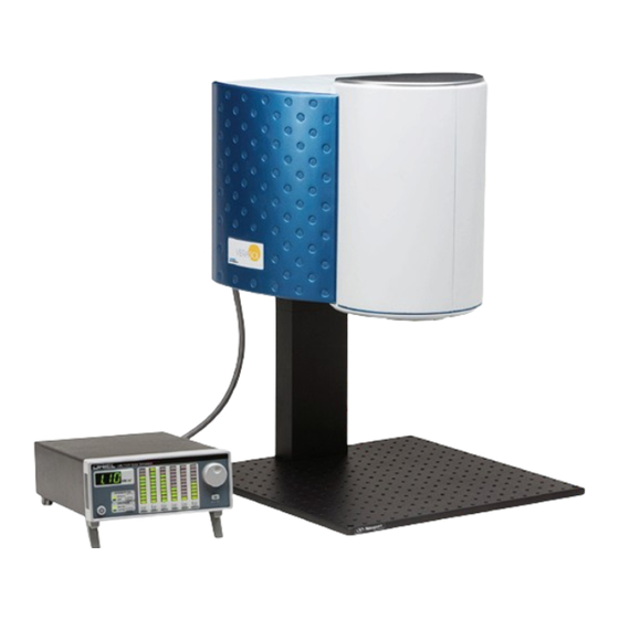
Chapter 1: Introduction and Specifications This chapter is an introduction to the VeraSol LED Solar Simulator consisting of the (patented) LSS-7120 LED Controller and LSH-7520 LED Head. Safety Considerations and unpacking information Product Overview Options and accessories ... -
Page 12: Product Overview
Product Overview Newport is proud to introduce the first in a series of innovative solar simulator designs utilizing ® LED light sources. The Oriel VeraSol is made up of the LSS-7120 LED Controller and (patented) the revolutionary LSH-7520 LED Head. The system provides a variable output from 0.1 SUN to 1.0 SUN over a 2”... - Page 13 Features of the LSS-7120 LED Controller include: 19 independently controlled LED wavelengths from 400 nm – 1100 nm Front panel control of the 6 IEC wavelength bands Rapid turn-on / turn-off Factory calibrated AM1.5G spectral match preset ...
- Page 14 Features of the LSH-7520 LED Head include: Fast turn on time, < 100ms –no shutter required 10,000 hour LED lifetime PV Cell Placement Indicator Optical support rod for easy height adjustment Can be mounted pointing up, down, or to the side with 90 rotational accessory ...
-
Page 15: Options And Accessories
Options and Accessories Options and accessories available for VeraSol-2 LED Solar Simulator: DESCRIPTION MODEL / PART NUMBER Single Rack Mount Kit RM-144 Solid Aluminum Optical Breadboard, 18 x 24 in., 1 in. 1/4-20 Grid SA2-18X24 Solid Aluminum Optical Breadboard, 450 x 450 mm, 25 mm M6 Grid M-SA2-18X24 LED Head Interconnect Cable CC720... -
Page 16: Specifications
Specifications PERFORMANCE SPECIFICATIONS Illumination Area (in.) [mm] 2 x 2 [50 x 50] Maximum Output Power 100 mW/cm (1.0 SUN) Variable Output Control 0.1 to 1.0 SUN Wavelength Range 400 – 1100 nm Nominal Working Distance (in.) [mm] 8.0 [200] Alignment Laser Diode-Based Optical Alignment 9.0 –... -
Page 17: Chapter 2: Assembly Instruction
Chapter 2: Assembly Instruction This chapter describes the assembly process for the VeraSol system. The VeraSol kit includes the following parts: 6-32 x 5/16” Flat Head Philip Screws Cover Plate ¼-20 x 2” Socket Head Cap Screws Vertical Adjustment Assembly ¼-20 x 1”... - Page 18 Tools Required: #1 Phillips Screw Driver 5/16 inch Ball Point Hex Driver (provided) 5mm Ball Point Hex Driver for assembly to metric optical bread board only Step 1: Secure (D) Vertical Adjustment Assembly to (H) Optical Bread Board. If you are securing it to an imperial units bread board use (E) 4 - ¼-20 x 1”...
- Page 19 90 Degree Head Mounting Instructions The LSH-7520 may be mounted at a 90 degree orientation by using the MA701 90 Degree Head Mount Adapter sold separately. To install the MA701 head mounting adaptor complete the following: MA701 Parts List ¼-20 x 1.75” Socket Head Cap Screws 90 Degree Adaptor Block Standard LSH-7520 Parts ¼-20 x 2”...
- Page 20 March 2019 VeraSol...
-
Page 21: Chapter 3: General Operation
Chapter 3: General Operation This chapter is an overview of the operation of the VeraSol-2 LSS-7120 LED Controller and LSH-7520 LED Head. Power requirements Front panel operation General operating procedures Grounding Requirements The LSS-7120 LED Controller comes with a three conductor AC power cable. The power cable must be plugged into an approved three-contact electrical outlet or used with a three-contact to two-contact adaptor with the grounding wire connected to an electrical ground (safety ground). -
Page 22: Firmware Upgradeability
Firmware Upgradeability The firmware on the LSS-7120 can be upgraded via USB. Contact Oriel Instruments technical support for information on upgrading the software. USB Communication The USB connector is located on the rear panel. The USB connector is the square "B"-style connector. -
Page 23: Front Panel Operation
Front Panel Operation This section describes the fundamentals of operation for the LSS-7120 Controller and the LSH-7520 LED Head. is the AC power on/off button. Pressing the POWER button applies power to the LSS-7120 Controller and starts the power up sequence described above. When turned on, the instrument provides power to temperature control the head. - Page 24 Bar Graph Display This bar graph display consists of six vertical banks of ten LEDs. Each LED can be green, red, or orange. When the output is Off the LEDs are orange. When the output is On the LED’s are green. When a band is selected for adjustment the LEDs will turn Red.
- Page 25 The 7 segment display will then read 1.00 to reflect the above change. Default Mode Instrument utilizes factory calibrated amplitude values for each LED. Default mode can be activated by either the front panel or remotely through USB. User Mode ...
- Page 26 Output On Button & Adjustment Knob Pressing the Output button turns the output on and off. When the output is on, the LEDs in the bar graph are all green. When the output is off, the LEDs are orange. If the output-on button is pressed to turn on the output, but there is no head connected, a message will briefly appear in the Numeric Display.
-
Page 27: Lsh-7520 Led Head Operation
LSH-7520 LED Head Operation The LSH-7520 is designed to reduce the amount of user adjustment required to ensure a uniform consistent output. The only user adjustment to the LED Head is the height adjustment and head orientation. Connection to LSS-7120 Controller The VeraSol system comes with the LSS-7120 Controller, Interconnect cable CC720, and LSH- 7520 LED Head. - Page 28 March 2019 VeraSol...
-
Page 29: Chapter 4: Remote Operation
Chapter 4: Remote Operation This chapter is an overview of the remote operation of the LSS-7120 Controller. Fundamentals of Remote Operation Command Syntax Status Reporting USB (Universal Serial Bus) is the common serial communication protocol used by most computers for relatively fast communication. - Page 30 Table 3.1 – Acceptable and Not Acceptable Spelling DEFINITION ACCEPTABLE NOT ACCEPTABLE OUTput OUT or output OU or outp AMPLitude AMPLitude or AmPL AMP or AMPLIT White Space “White space” is any number of space characters (space bar). A white space must separate a command from its parameters or data.
-
Page 31: Chapter 5: Command Reference
Chapter 5: Command Reference This chapter is a guide to all of the commands for the LSS-7120 LED Controller. . Overview of the remote commands List of remote commands in alphabetical order Remote Command Reference Summary This section contains all of the commands for the LSS-7120. Table 4.1 –... -
Page 32: Command Reference
Returns a string of instrument identification information. The string contains a comma separated list of manufacturer, model number, serial number, and firmware revision. Examples “*IDN?” Responds with “Newport Corporation,LSS-7120,71201234,1.01” (serial # 71201234, rev 1.01) AMPLitude <suns> AMPLitude? Description Sets or reports the output power of the Head relative to number of suns (1 kW/m Parameters suns –... - Page 33 LEDTEST:POWER? Description Sequentially turns on each LED while measuring the output power. Parameters None Return Returns 1 when the test is finished. Returns 0 if the test fails due to a hardware problem. NOTE: the test takes several seconds before it returns a result. LEDTEST:RESULT? <LED #>...
- Page 34 STATus? Description Requests the status of the LSS-7120. Response A decimal number containing bit-encoded information: If bit 0 is set, the output is on. Bit 1: reserved If bit 2 is set, the head is disconnected (check the cable). If bit 3 is set, the head has not yet warmed up to its optimum operating temperature. If bit 4 is set, the head temperature is above its optimum operating range.
-
Page 35: Chapter 6: Remote Control Software
Chapter 6: Remote Control Software The VeraSol system includes a remote software application to aid the user in setting custom spectrums and to perform system functional tests. The software can be found on the USB thumb drive provided with the unit. Setup executables on the thumb drive will update the USB drivers to allow access to the instrument, and also load the VeraSol Control Panel application. -
Page 36: Operation
Operation A – Connection This section is used to connect to the instrument. You must first connect a USB cable between your computer and the instrument. Follow the installation instructions above to load and install the appropriate drivers for the system. This area displays: ... - Page 37 The test also measures the operating temperature of the LEDs. The LEDs are temperature controlled to ensure consistent output power. A green head-temperature indication means the LEDs are operating at the specified temperature. The unit typically takes 15 minutes to reach nominal operating temperature.
- Page 38 March 2019 VeraSol...
-
Page 39: Chapter 7: Verasol Replicator
Chapter 7: VeraSol Replicator This chapter is to help guide the user through the use of the VeraSol Replicator software. VeraSol Replicator gives the user a method to generate a solar spectrum based on geographic location, as well as date and time of day. This spectrum is used to generate a VeraSol LED spectrum, replicating the solar spectrum. - Page 40 A file search capability as designated by the folder icon allows the user to locate a file of choice. When entering the file name directly via the Input File text box, only the preface part of the file name is required. If the file cannot be located, an appropriate error message will be presented to the user.
-
Page 41: Output File
Output File Specifying an output file designation is optional. If not provided, it results in the default creation of the position file in the default “C:\Users\<username>\Documents\VeraSolReplicator Data” directory. The name provided by the user in the Output File text box is used in the creation of the resulting position data file, VeraSol Simulator data file, and screen shot of the generated spectrum report. -
Page 42: Location Helper
Location Helper A location helper function has been incorporated into the dialog, assisting the user in setting correct values for position (latitude / longitude) and UTC Time Zone offset. Selecting the Location button provides the user with a pop-up dialog for entering location information to be used by a Geo-coder in doing a search. -
Page 43: Utc
A UTC helper function has been incorporated into the dialog, to assist the user in setting correct values for UTC Time Zone offset. Selecting the UTC button uses the latitude / longitude specification, in conjunction with the Date and Hour specification, to calculate the correct UTC Time Zone offset. -
Page 44: Download To Verasol
Download to VeraSol The Download to VeraSol button downloads the appropriate LED intensity settings to VeraSol that most closely represent the solar spectrum. If the LSS-7120 is offline, a pop-up error message will be presented to the user indicating that fact. Upon completion of the download, the user is presented with an indication of a successful download via another pop-up dialog. -
Page 45: Chapter 8: Calibration And Troubleshooting
Chapter 8: Calibration and Troubleshooting This chapter is to help you resolve any problems you may experience with your LSS-7120 Controller or LSH-7520 LED Head. If you need additional help, please contact Oriel Instruments Customer Service. See page viii for contact information. Oriel Instruments provides in-house calibration services. - Page 46 Error Messages A user may see the errors the unit has stored in the error queue by sending the “ERROR?” query. The unit retrieves and sends one error from the queue in response to the “ERROR?” query. To see all the errors, continue to send the “ERROR?” query until the response is “0”. ERROR EXPLANATION CODE...
Need help?
Do you have a question about the Oriel VeraSol LSS-7120 and is the answer not in the manual?
Questions and answers