Table of Contents
Advertisement
Advertisement
Table of Contents

Related Manuals for jcb 19C-1E


Summary of Contents for jcb 19C-1E
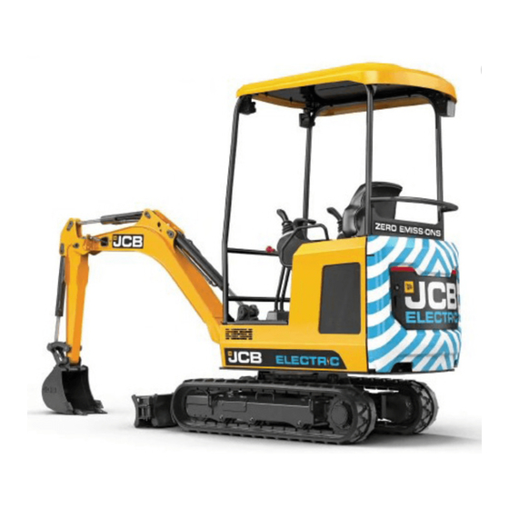
- Page 1 Quick Start Guide INSERT MODEL IMAGE JCB ELECTRIC COMPACT EXCAVATOR 19C-1E...
- Page 2 Operation of this machine without periodic maintenance could cause it to malfunction. For more information please contact your JCB Dealer. WARNING: This machine uses a 48V electrical powertrain system. DO NOT work on this machine unless you are suitably trained, competent and...
-
Page 3: Table Of Contents
19C-1E INDEX Intended Use Electrical Powertrain Specification Dimensions Dig Performance Tie Down Points 8-10 Lifting Points Cab & Control Layout 12-14 Instrumentation Panel Hydraulic Control Layout Start Up Sequence Hitch Unlock Sequence 17-18 Auxiliary Venting & Shutdown Charging Levels & Charging... -
Page 4: Intended Use
19C-1E INTENDED USE General • Machine Type – Compact Excavator • Self propelled machine with a tracked undercarriage • 360° revolving upper structure with boom, dipper, bucket and slew mechanism Intended Use • Machine intended to be used in normal conditions as detailed in the operators manual •... -
Page 5: Electrical Powertrain Specification
19C-1E ELECTRICAL POWERTRAIN SPECIFICATION Battery Type Manganese laminated Lithium-ion 14.8 kWh (3 Pack) Battery Rated Capacity 19.8 kWh (4 Pack) System Voltage Motor Type AC permanent magnet 7 kW continuous Motor Power 20kW peak On-board charger with direct connection from AC mains... -
Page 6: Dimensions
19C-1E DIMENSIONS Fig.1 Description 19C-1E Sprocket idler centres 1218 Track length on ground 1220 Undercarriage overall length – rubber 1578 Undercarriage overall length – steel 1578 Kingpost clearance Tail swing radius 1103 Overall width of superstructure Height over cab 2324 Ground clearance Track gauge –... -
Page 7: Dig Performance
19C-1E DIG PERFORMANCE Fig.2 Description 19C-1e Boom length 1800 Dipper length 1100 Maximum digging reach 4043 Maximum digging reach on ground 3981 Maximum digging depth – dozer up 2421 Maximum digging depth – dozer down 2576 Maximum digging height 3667... -
Page 8: Tie Down Points
19C-1E TIE DOWN POINTS When transporting the machine one of the following two methods should be used: Method 1 Fig. 3 A – Front undercarriage track leg tie- B – Rear undercarriage track leg tie-down down points points C – Angle = 25° to 45°... - Page 9 19C-1E TIE DOWN POINTS Method 2 Fig. 4 A – Front slew spine tie-down point B – Rear slew spine tie-down point C – Angle = 35° to 46° D – Angle = 45° to 50° E – Angle = 9° to 15°...
- Page 10 19C-1E TIE DOWN POINTS Method 3 Fig. 5 A – Front slew spine tie-down point B – Rear slew spine tie-down point C – Angle = 35° to 46° D – Angle = 35° to 45° E – Angle = 9° to 15°...
-
Page 11: Lifting Points
19C-1E LIFTING POINTS Fig. 6 Description 19C-1e Boom Lift Point Dozer Blade Lift Point Spreader Bar Centre of Gravity Fig. 6 The correct lifting positions are identified on the machine by their LIFTING POINT labels: POSITION LABEL Please see operator manual for full details. - Page 12 19C-1E CAB & SWITCH PANEL Operator Station Layout Fig. 7 A – Track controls B – Control lever C – Track extension lever D – Dozer blade control lever E – Ignition switch F – Motor running indicator light G – Rotary hand throttle control H –...
- Page 13 19C-1E CAB & SWITCH PANEL Switch Panel Fig. 8 Window Wipers Work Lights Beacon 1 = Off 1 = Off 1 = Off 2 = Intermittent / continuous / 2 = On (Boom) 2 = On washer 3 = On (Boom & Cab)
- Page 14 19C-1E INSTRUMENT PANEL Instrument Panel – 19C-1E Fig. 10 Fig. 11 Charger connected Dozer float Hydraulic oil-over High speed travel temperature System over Swing active temperature Li- ion battery system SAE active fault 12V battery charging Master warning Motor fault...
- Page 15 19C-1E JOYSTICK & DOZER LEVER Swing Controls Auxiliary Controls Fig. 12 Fig. 13 A – Tilt/grab changeover for tilt-rotator A – Swing left B – Boom swing/Aux change over button B – Swing right C – Thumb wheel control – Aux 2 (Low flow) C –...
-
Page 16: Start Up Sequence
19C-1E START UP SEQUENCE Raise Pod Arm Engage Seat Belt Power Machine On Ensure the hydraulic isolation Engage seat belt (A) into Insert key in to ignition lever (left hand arm rest) is in latch (B) before starting switch, and turn to position I. -
Page 17: Hitch Unlock Sequence
19C-1E HYDRAULIC HITCH UNLOCK SEQUENCE Standard Attachments Start Unlock Process Confirm Process Boom LED Indicator To start quick hitch unlock Instrument panel will indicate When the sequence is process ensure hydraulics are need to confirm process (A). confirmed the LED on the... - Page 18 19C-1E MECHANICAL HITCH UNLOCK SEQUENCE Standard Attachments Park Machine Up Insert tommy bar Disconnect Attachment Park the machine on firm level Stop the motor, remove any Insert the tommy bar into ground. Position the connected hydraulic hoses the hole of the latch hook attachment (A) just above the and remove the locking pin.
- Page 19 19C-1E SHUTDOWN & AUXILIARY VENTING Auxiliary Venting (Within 1 Minute of Motor Shutdown) Lower LH Arm Rest Machine Power On Press 2 GO Button While sitting in the operating Turn ignition switch to Press 2 GO button (A) to station with motor off lower position 1 so that the activate hydraulics.
-
Page 20: Charging Levels & Charging
If further issues occur, unplug the charging cable and contact your local JCB Dealer. If there is a fault with the power supply the status LED will alternate green and red. -
Page 21: Maintenance Position
19C-1E MAINTENANCE POSITION Park the machine on solid, level ground Release the two track levers Set the hand throttle dial to the idle position Lower the dozer blade Lower the excavator so the attachment is flat on the ground Fig. 18 A –... - Page 22 19C-1E SERVICE / MAINTENANCE Daily Checks (10h) Check Check condition of hydraulic cooling pack and system Visual Check Check hydraulic oil level Visual Check Check the condition of welded structure Visual Check Check condition of bodywork and framework Visual Check...
-
Page 23: Access Covers
19C-1E ACCESS COVERS – SERVICE ITEMS AND RELAYS Fig. 19 Fig. 20 A – Lock A – Fixings B – Service compartment cover B – Relay access cover C – Handle Fig. 21 A – Grease gun B – Service disconnect C –... - Page 24 19C-1E ACCESS COVERS – FLUID LEVELS AND FILL Fig. 22 A – Hydraulic compartment cover B – Lock Fig. 23 A – Hydraulic tank filler cap B – High voltage batteries charging point C – Hydraulic oil level indicator Please see operator manual for full details.
-
Page 25: Fluids & Lubricants
19C-1E FLUIDS & LUBRICANTS J C B Part Container Item Capacity Fluid/Lubricant Number Size JCB Engine Oil HP SAE 30 (Not Track Gearbox (each) 0.3L 4001/0305 Multigrade) Track Idler Wheels 0.3L JCB HP90 Gear Oil 4001/0305 Track Rollers 0.025L JCB HP90 Gear Oil... -
Page 26: Machine Attachments
19C-1E MACHINE ATTACHMENTS Weight H y d r a u l i c Description I n t e n d e d U s e (kg) R e q u i r e m e n t s Mechanical Quickhitch 13.7... -
Page 27: Troubleshooting / Faqs
19C-1E TROUBLESHOOTING / FAQ’S Issue / FAQ Resolution / Answer My machine will not start Ensure the service disconnect is turned on. Verify the start up sequence has been followed (Page 16). If machine still will not start contact dealer I can’t activate the Hydraulics... - Page 28 19C-1E TROUBLESHOOTING / FAQ’S Issue / FAQ Resolution / Answer 500hrs Greasing - Do the bushes No, just grease and continue work need to be replaced at 500hrs? 500hrs Greasing - After the first No, the bushes wont need greasing until the next 500hrs...
- Page 29 J C B Sales Limited, Rocester, Staffordshire, United Kingdom ST14 5JP Tel: +4 4 1889 590312 Email: salesinfo@jcb.com Download the very latest information on this product range at: www.jcb.com The J C B logo is a registered trademark of J C Bamford Excavators Ltd. ©2009 J C B Sales.
Need help?
Do you have a question about the 19C-1E and is the answer not in the manual?
Questions and answers