
Related Manuals for TAJIMA SAI MDP-S0801C(200×300)S


Summary of Contents for TAJIMA SAI MDP-S0801C(200×300)S
-
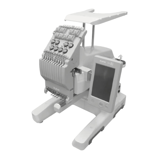
Page 1: Embroidery Machine
Embroidery machine Operation Manual MDP-S0801C(200×300)S Please keep this manual in handy even after use for future reference. - Page 3 Introduction Thank you, and congratulations on your purchase of the SAI 彩 (MDP-SC). Before using this embroidery machine, make sure to thoroughly read this manual, so you are certain you have gained a sufficient grasp of all the procedures required to operate it. Manual organization The manuals for this machine are organized as follows.
-
Page 4: Table Of Contents
Table of contents Table of contents Important Safety Instructions ........4 WARNING stickers . - Page 5 Table of contents 4.7 Setting the thread colors ......... . 55 4.7.1 Selecting from the database .
-
Page 6: Important Safety Instructions
Important Safety Instructions IMPORTANT SAFETY INSTRUCTIONS Read all instructions before using this appliance. When using an electrical appliance, basic safety precautions should always be followed, including the following: DANGER To reduce the risk of electric shock: An appliance should never be left unattended when plugged in. Always unplug this appliance from the electric outlet immediately after using and before cleaning. - Page 7 Important Safety Instructions If smoke, strange odors, or abnormal sounds are emitted Switch OFF the power switch, and pull out the plug of the power cord from the outlet. Then contact your sales dealer. To prevent fire, electrical shock, and malfunctions In each of the following situations, switch OFF the power switch, and pull out the plug of the power cord from the outlet.
- Page 8 Important Safety Instructions To reduce the risk of burns, fire, electric shock, or injury to persons: Do not allow children to use the machine as a toy Do not allow to be used as a toy. Close attention is necessary when this appliance is used by or near children.
- Page 9 Important Safety Instructions To reduce the risk of burns, fire, electric shock, or injury to persons: Use only for intended purpose Use this appliance only for its intended use as described in this manual. Use only attachments recommended by the manufacturer as contained in this manual.
- Page 10 Important Safety Instructions CAUTION Minor injury or property damage may result if the following instructions are not adhered to. Avoid unsuitable environments for using/storing the unit Do not use or store the machine in any of the following places: Otherwise, malfunction, discoloration, or deformation may occur.
- Page 11 Important Safety Instructions If the machine is dropped, damaged, or fails to function properly Immediately stop use of the machine and contact your sales dealer. When air conditioning devices are used Take care so as not to allow the airflow from an air conditioning device to directly strike the machine.
- Page 12 Important Safety Instructions GROUNDING INSTRUCTIONS (For USA and Canada only) This product must be grounded. In the event of malfunction or breakdown, grounding provides a path of least resistance for electric current to reduce the risk of electric shock. This product is equipped with a cord having an equipment-grounding conductor and a grounding plug.
- Page 13 Important Safety Instructions [When the product is used in a nominal rating up to 120V] This product is for use on a nominal 120V circuit, and has a grounding plug that looks like the plug illustrated in sketch A in Figure-1. A temporary adaptor, which looks like the adaptor illustrated in sketches B and C, may be used to connect this plug to a 2-pole receptacle as shown in sketch B if a properly grounded outlet is not available.
- Page 14 Important Safety Instructions Statement on FCC Rules (For USA Only) This device complies with part 15 of the FCC Rules. Operation is subject to the following two conditions: (1) This device may not cause harmful interference, and (2) this device must accept any interference received, including interference that may cause undesired operation.
-
Page 15: Warning Stickers
Important Safety Instructions WARNING stickers A number of WARNING stickers are affixed to the machine. Carefully observe the messages contained in the WARNING stickers, and use the machine safely. Do not remove any of the WARNING stickers. Do not damage or deface them. If any of the WARNING stickers are no longer in place, or have become difficult to read, please contact your sales dealer. -
Page 16: Chapter 1 Let's Learn The Names Of Things And What They Do
Chapter 1 Let's Learn the Names of Things and What They Do Chapter 1 Let's Learn the Names of Things and What They Do 1.1 Machine main unit Number Name Function Thread tension Adjusts the tension of the upper thread. Slides to right and left;... - Page 17 Chapter 1 Let's Learn the Names of Things and What They Do Number Name Function Used to connect a USB memory or barcode reader. Used mainly when USB port (*) connecting a USB memory. Frame drive system Moves the frame forward and back, and right and left. LAN port Used to connect a LAN cable.
-
Page 18: Home Screen
Chapter 1 Let's Learn the Names of Things and What They Do 1.2 Home screen After the power switch is turned ON, the following Home screen appears on the operation panel. 3 4 5 Number Icon Description Current needle (No. 1 to 8) is displayed. is displayed while the laser crosshair marker is lit. -
Page 19: Basic Operations On The Screens
Chapter 1 Let's Learn the Names of Things and What They Do 1.3 Basic operations on the screens The operation panel is a touch screen. To switch among screens, make settings, etc., simply tap the icons displayed on the touch screen with your finger or the stylus packed with the machine. -
Page 20: Chapter 2 Getting Ready To Embroider
Chapter 2 Getting Ready to Embroider Chapter 2 Getting Ready to Embroider Before you start using the machine, prepare the needles, thread, and the fabric on which the embroidery is to be performed. 2.1 Replacing needles Before you start embroidering, check the condition of the needles, and if any of them are bent or broken, replace them with new needles following the procedure below. -
Page 21: Threading The Upper Thread
Chapter 2 Getting Ready to Embroider 2.2 Threading the upper thread The following illustration shows the places through which the upper threads for each needle should be passed. Carefully thread each upper thread, making sure that its path is correct at each position. The numbers that appear in the illustration below correspond to the needle numbers. - Page 22 Chapter 2 Getting Ready to Embroider Hook the upper thread onto the tip of the upper thread guide (Accessory part), and insert it into the thread tube. Continue inserting until the threader comes out from the thread tube opening that is fixed in the tension base. Once the upper thread has through the thread tube opening, thread it as shown in the illustration to the right.
- Page 23 Chapter 2 Getting Ready to Embroider As illustrated to the right, place the upper thread on the center thread course of the needle bar case, and then thread it through the hole at the top. The upper thread can be threaded through the hole in the take-up lever more easily if it is folded in two.
- Page 24 Chapter 2 Getting Ready to Embroider Using spool nets When using metallic threads (gold or silver threads) or threads with high tensile strength, spool nets (Accessory part) should be placed over the spools. By using spool nets, you can help prevent thread snarling.
-
Page 25: Setting The Under Thread
Chapter 2 Getting Ready to Embroider 2.3 Setting the under thread Initially, only the bobbin case is installed in the rotary hook and you will need to install a bobbin before running the machine. First, take the bobbin case out of the rotary hook. Then, after winding the under thread onto the bobbin, place it in the bobbin case. -
Page 26: Placing In Rotary Hook
Chapter 2 Getting Ready to Embroider Adjust the tension of the under thread. Suspend the bobbin case by holding the end of the thread, and swing it back and forth. If the under thread comes out slowly, it means that the tension is set to the appropriate amount. If an adjustment is necessary, turn the thread tension adjustment screw using the bobbin-case-use flat head screwdriver. -
Page 27: Setting Up The Embroidery Frame
Chapter 2 Getting Ready to Embroider Close the front cover of the bed. 2.4 Setting up the embroidery frame There are two sizes of embroidery frames available, one large, one small. Select the appropriate one to use depending on the size of the design. Note that you must change the settings for the frame on the operation panel whenever you change the embroidery frame. -
Page 28: Attaching An Embroidery Frame
Chapter 2 Getting Ready to Embroider Loosely tighten the adjustment screw on the outer frame, and then smooth out the cloth within the frame to remove any looseness or wrinkles. Stretch out the fabric only to the extent that none of its weave is disturbed in any way. -
Page 29: Chapter 3 How To Perform Embroidery
Chapter 3 How to Perform Embroidery Chapter 3 How to Perform Embroidery In the following we will explain the steps you need to take to perform embroidery from start to finish. First, get needles, thread, and fabric ready. Then, follow along with this manual and perform the actual operations. - Page 30 Chapter 3 How to Perform Embroidery If an embroidery has been paused partway through, and the power has been cycled, the Paused screen is displayed instead of the Home screen.
-
Page 31: Starting The Embroidery
Chapter 3 How to Perform Embroidery 3.2 Starting the embroidery In the following, we will explain the steps you need to take before performing an embroidery. 3.2.1 Loading the design to be embroidered Using any of the following methods, load the design to be embroidered. •... - Page 32 Chapter 3 How to Perform Embroidery Tap a folder to select designs that are contained in the folder. The root folder and three levels of subfolders of the USB memory (USB flash drive) are loaded. Up to 255 designs contained in a folder can be displayed in the List screen. Root folder Subfolder (first level) Subfolder (second level)
-
Page 33: Setting The Needle Number
Chapter 3 How to Perform Embroidery 3.2.2 Setting the needle number With some designs, the thread color and needle number for each step (order, for each color, in which embroidery is to take place) are already assigned in the design. Even without changing the settings for steps, for each step in the design, the upper thread of the color that you want to embroider can be set for the set needle No., allowing embroidery to take place using the correct color order. -
Page 34: Setting The Orientation Of The Design And The Start Point
Chapter 3 How to Perform Embroidery 3.2.3 Setting the orientation of the design and the start point Here's how to set the orientation of the design and the embroidery start point. Select the orientation of the design. • To leave it in the original position: •... -
Page 35: Moving The Frame To The Embroidery Start Point
Chapter 3 How to Perform Embroidery 3.2.4 Moving the frame to the embroidery start point Manually, move the frame to the embroidery start point. Caution Keep hands away from the area surrounding the frame. Otherwise, there is a risk of injury due to the movement of the frame. -
Page 36: Confirming That The Design Fits Within The Embroidery Area
Chapter 3 How to Perform Embroidery 3.2.5 Confirming that the design fits within the embroidery area By using the trace function, which moves the frame in accordance with the contour of the design, you can find out whether the embroidery design is appropriate or not, and whether the allowable area for embroidery will be exceeded or not. -
Page 37: Selecting The Speed
Chapter 3 How to Perform Embroidery If you have determined, as the result of the trace, that there are no problems with the embroidery position, tap The Embroidery Start screen is displayed. If a start message has been set for the design, the start message screen is displayed. 3.2.6 Selecting the speed Three speeds are available: high speed, medium speed, and low speed. -
Page 38: Starting The Embroidery
Chapter 3 How to Perform Embroidery 3.2.7 Starting the embroidery The following explains each item on the Embroidery Start screen. Number Icon Description Opens the Trace screen. "3.2.5 Confirming that the design fits within the embroidery area" Opens the Sewing Speed Setting screen. "3.2.6 Selecting the speed"... - Page 39 Chapter 3 How to Perform Embroidery While the Embroidery Start screen is displayed, press the [START] button on the operation panel. The embroidery starts. An image of the design is displayed on the operation panel, and the current position of the needle is indicated with a marker. Also, areas where embroidery has been completed are shown in gray.
-
Page 40: Pausing The Machine
Chapter 3 How to Perform Embroidery 3.2.8 Pausing the machine While embroidery is in progress, the machine can be paused. Press the [STOP] button on the operation panel while embroidery is in progress. The machine stops and the Paused screen is displayed. The following explains items not displayed on the Embroidery Start screen. - Page 41 Chapter 3 How to Perform Embroidery Resuming embroidery Press the [START] button on the operation panel. Embroidery resumes from the paused position. Starting the embroidery again from the beginning , and then tap [YES]. Thread is trimmed automatically, and embroidery is stopped. Also, you are returned to the Embroidery Start screen.
-
Page 42: When Thread Breaks During Embroidery
Chapter 3 How to Perform Embroidery 3.2.9 When thread breaks during embroidery When thread breakage is detected, the machine stops automatically and an error is displayed. You should deal with this in the following methods, depending on the content of the error. When "Upper Thread Break"... -
Page 43: Ending The Embroidery
Chapter 3 How to Perform Embroidery 3.3 Ending the embroidery 3.3.1 Removing the frame and fabric While lifting the front of the frame, remove the frame from the machine's frame holder. Disengage the clips on the inner frame. Take away the fabric. 3.3.2 Checking the tension of the upper thread If the under thread is appearing on the front of the fabric, you should lower the thread tension of the upper thread. -
Page 44: Turning Off The Machine's Power
Chapter 3 How to Perform Embroidery To check the tension of the upper thread, the thread lock needs to be in the raised position as shown below. It cannot be checked properly if the thread lock is not raised. 3.3.3 Turning off the machine's power Turn off the machine's power switch. -
Page 45: Chapter 4 Getting The Most Out Of The Machine
Chapter 4 Getting the Most Out of the Machine Chapter 4 Getting the Most Out of the Machine Your machine offers a variety of convenient functions. For example, you can easily search for designs that have been used before, you can set the order in which a design is to be sewn, and you can carry out repair sewing. -
Page 46: Storing A Design As A Favorite Or Removing It
Chapter 4 Getting the Most Out of the Machine 4.2 Storing a design as a favorite or removing it From the Record screen, designs you've used before can be stored in the Record. By storing a design that you use frequently, it can conveniently be called up the next time you want to use it. - Page 47 Chapter 4 Getting the Most Out of the Machine Removing a design from the favorites on the Design Load screen. The Design List screen is displayed. Tap the design you want to remove from the favorites. displayed at the lower left corner of the screen changes The confirmation screen is displayed.
-
Page 48: Loading Designs From Records Or Favorites
Chapter 4 Getting the Most Out of the Machine 4.3 Loading designs from records or favorites Designs that have been loaded before, and designs that have been stored in the favorites can be selected from Record or Favorite, and then used to perform embroidery. Once a design has been loaded, it is stored in Record. -
Page 49: Loading A Design From A Pc Using A Lan Cable
Chapter 4 Getting the Most Out of the Machine 4.4 Loading a design from a PC using a LAN cable Designs from the dedicated design creation software or a separately available DG product on a PC can be loaded into the machine after it has been connected to the PC using a LAN cable. If you want to directly connect the PC to the machine, you will need to prepare a commercially available cross-cable. -
Page 50: Loading A Design Using A Barcode Reader
Chapter 4 Getting the Most Out of the Machine The Design List screen is displayed, select the design to be loaded. Next, perform the steps that need to be carried out before you can start embroidery, such as setting the needle numbers and the embroidery start point. -
Page 51: Editing The Steps Of A Design
Chapter 4 Getting the Most Out of the Machine 4.6 Editing the steps of a design With some designs, the thread color and needle number for each step (order, for each color, in which sewing is to take place) are already assigned to the design. The following explains the steps you need to take if you want to carry out embroidery using needle numbers different than those stored within the design. -
Page 52: Needle No. Setting Screen
Chapter 4 Getting the Most Out of the Machine 4.6.1 Needle No. Setting screen Number Icon Description Displays the design-load source. Displayed while setting thread colors and steps. If you've arrived at this screen from the Pause screen, this icon is not displayed. -
Page 53: Setting The Needle Number
Chapter 4 Getting the Most Out of the Machine 4.6.2 Setting the needle number In the Needle No. Setting screen, tap the icon for the step for which you want to set the needle No. The icon of the step that was tapped and the needle No. set for the step are highlighted in yellow. -
Page 54: Bringing The Frame Out
Chapter 4 Getting the Most Out of the Machine Repeat steps 1 and 2 until all steps have a needle number assigned to them. The step is set. 4.6.3 Bringing the frame out While embroidery work is in progress, the machine can be paused and the frame can be brought out in front of the machine. -
Page 55: Pausing
Chapter 4 Getting the Most Out of the Machine 4.6.4 Pausing While a step is in progress, the machine can be paused. In the Needle No. Setting screen, tap one of the step icons to which the pause is to be added. The icon of the step that was tapped and the needle No. -
Page 56: Repeating Step
Chapter 4 Getting the Most Out of the Machine 4.6.5 Repeating step This function allows specific steps to be repeated. After the step repetition operation has been inserted, the step before that will be executed repeatedly. On the Needle No. Setting screen, tap the icon for the step into which the step repetition is to be inserted. -
Page 57: Setting The Thread Colors
Chapter 4 Getting the Most Out of the Machine 4.7 Setting the thread colors The thread color can be set for each needle No. There are two ways of selecting thread colors. They can be selected from the database contained in the machine, or they can be selected from the color palette. - Page 58 Chapter 4 Getting the Most Out of the Machine Select the thread color, and then tap Once the color has been selected, the [Name] and [Code] are displayed. You are returned to the List of Thread Color Setting screen. Repeat steps 2 through 4 until the maker and color have been set for all needles up to needle No.
-
Page 59: Selecting From The Color Palette
Chapter 4 Getting the Most Out of the Machine 4.7.2 Selecting from the color palette on the Home screen. The List of Thread Color Setting screen is displayed. The needle No. 1 Color Palette screen is displayed. Select the thread color for needle No. 1, and then The needle No. -
Page 60: Bringing The Frame Out Quickly
Chapter 4 Getting the Most Out of the Machine 4.8 Bringing the frame out quickly When the machine is stopped, the frame can be brought out quickly. This function can be conveniently used when you want to check the condition of the embroidery while it is being sewn, or when you want to change the frame. -
Page 61: Returning Frame/Advancing Frame According To Design
Chapter 4 Getting the Most Out of the Machine 4.9 Returning frame/advancing frame according to design The frame can be returned or advanced according to the design data. This feature comes in handy in the following situations. • When you want to do some repair stitching after the thread has broken, and you want to restart the embroidery from the position before the thread broke. -
Page 62: Manual Operation
Chapter 4 Getting the Most Out of the Machine 4.10 Manual operation When the machine is stopped, movement of the frame, needle bar changes, and thread trimming can be performed manually. 4.10.1 Moving the frame manually The frame can be moved to any position you want. When the frame can be moved manually, is displayed on the screen. -
Page 63: Manually Changing The Needle Position
Chapter 4 Getting the Most Out of the Machine 4.10.2 Manually changing the needle position The needle for the sewing start point can be changed by sliding the needle bar case. When the needle bar case can be operated manually, is displayed on the screen. -
Page 64: Trimming The Thread Manually
Chapter 4 Getting the Most Out of the Machine 4.10.3 Trimming the thread manually The thread can be trimmed manually. When the thread can be trimmed manually, is displayed on the screen. Caution Keep hands away from the area surrounding the needles and frame. Otherwise, there is a risk of injury when the needles come down and the frame moves. -
Page 65: Using The Laser Crosshair Marker
Chapter 4 Getting the Most Out of the Machine 4.11 Using the laser crosshair marker The laser crosshair marker provides a cross-shaped laser illuminated area on the fabric, which indicates the position the needle will fall. When lighted, the laser crosshair marker makes it easy to adjust positioning when the frame is moved, such as when moving the frame to a position to be embroidered. -
Page 66: Using Design Creation Software
Chapter 4 Getting the Most Out of the Machine 4.12 Using design creation software Designs can be created on a PC using the dedicated design creation software or a separately available DG product. Once a design is created, USB memory (USB flash drive) or the network functionality can be used to load the design into the machine, and use it for embroidery. -
Page 67: Chapter 5 Lettering Embroidery
Chapter 5 Lettering Embroidery Chapter 5 Lettering Embroidery Text such as initials or names can be embroidered using combinations of the fonts stored in the machine. Designs created using the lettering embroidery function can consist of only one color. Textual embroidery designs that have been created are automatically given a file name when they are stored in Record. - Page 68 Chapter 5 Lettering Embroidery to set the maximum width of the character string, and then tap The Text Height Setting screen is displayed. The maximum width of the character string can be set to any value from 5 to 300 mm. Select the character height, and then tap •...
- Page 69 Chapter 5 Lettering Embroidery The Confirm Image screen is displayed. • 1: Name of design • 2: Image of design • 3: Horizontal width of set design (in mm units) • 4: Number of stitches in design • 5: Height of set design (in mm units) The character spacing selection icons ([Whole] or [Part]) are displayed to the right of the icon.
- Page 70 Chapter 5 Lettering Embroidery If [Part] was tapped in step 7, tap and select the two characters for which the spacing is to be set. The character spacing can be set to any value from -50 to 100 mm. (The default setting is 0.5 mm.) The two characters that were selected are displayed in red.
-
Page 71: Chapter 6 Setting The Machine
Chapter 6 Setting the Machine Chapter 6 Setting the Machine Settings for the machine, such as those for the embroidery frame or those on how the machine is to be used, are explained in the following. Please refer to this chapter for the convenient settings, such as if you would like to adjust the settings of the network and frame movement, or change the wallpaper of the operation panel. -
Page 72: Detecting Thread Breakage
Chapter 6 Setting the Machine Once the setting has been made, tap You are returned to the Setting screen. To cancel a setting, tap A confirmation screen is displayed, tap [YES], the selected setting will return to its previous state. 6.1.1 Detecting thread breakage This setting specifies whether or not breakage of the upper thread or under thread is to be detected. -
Page 73: Sewing Return Stitches At The Beginning Of The Embroidery
Chapter 6 Setting the Machine 6.1.2 Sewing return stitches at the beginning of the embroidery This setting determines whether or not return stitches are sewn at the beginning of the embroidery. When this setting is enabled, return stitches―two times back and fourth―are sewn at the beginning of embroidery. -
Page 74: Moving The Needle Bar Case After The Design Has Been Embroidered
Chapter 6 Setting the Machine 6.1.4 Moving the needle bar case after the design has been embroidered This setting determines whether or not the needle bar case moves to the position of the laser crosshair marker after the design has been embroidered, and the laser crosshair marker lights. Having the laser crosshair marker light makes it easier to decide the position of the next design to be embroidered. -
Page 75: Frame Settings
Chapter 6 Setting the Machine 6.2 Frame settings 6.2.1 Setting the type of frame to be used The frame settings need to be modified according to the type of frame to be used. Caution If the settings are not suitable for the frame being used, the frame could come into contact with parts of the machine and cause damage to the frame or the machine itself. -
Page 76: Memorizing The Frame Origin
Chapter 6 Setting the Machine 6.2.2 Memorizing the frame origin Whenever you change to a different type of frame, the frame origin needs to be memorized in the machine. The "frame origin" refers to the absolute coordinate values (X: 0.0, Y: 0.0) that are used for reference when calculating the current position of the frame. - Page 77 Chapter 6 Setting the Machine Tap [YES]. The frame moves, and the process for memorizing the frame origin is carried out. Once the frame origin has been successfully memorized, you will be returned to the Frame Setting screen.
-
Page 78: Memorizing The Frame Origin Upon Power Up
Chapter 6 Setting the Machine 6.2.3 Memorizing the frame origin upon power up This setting determines whether or not a message related to memorizing the frame origin is displayed when the machine's power is turned on. on the Home screen. The Setting screen is displayed. -
Page 79: Setting The Permissible Range Of Movement For The Frame
Chapter 6 Setting the Machine 6.2.4 Setting the permissible range of movement for the frame This setting determines whether or not a permissible range of movement (frame limits) for the frame is to be set. The machine is originally set so that the frame cannot be moved beyond the range inside the frame in which embroidery can be performed. -
Page 80: Returning The Frame To Its Original Position After Manually Moving It
Chapter 6 Setting the Machine If [NO] was selected in step 3, a confirmation message is displayed, so tap [YES]. Once a setting has been completed, you will be returned to the Frame Setting screen. 6.2.5 Returning the frame to its original position after manually moving it This setting determines whether or not the frame is to be moved back to the original point after it has been moved manually when the machine was stopped partway through a design. -
Page 81: Performing Network Settings
Chapter 6 Setting the Machine Tap [YES] or [NO] for [Return the frame after manual frame travel]. • To have the frame move back to its original position after it has been moved manually, and then resume the embroidery: [YES] (default setting) •... - Page 82 Chapter 6 Setting the Machine Tap [DHCP], and then select [YES] or [NO]. • When using a DHCP server or router: [YES] • When manually setting network addresses such as the IP address: [NO] If [NO] was selected in step 4, tap [IP Address], [Subnet], [Gateway].
-
Page 83: Setting The Date And Time
Chapter 6 Setting the Machine 6.4 Setting the date and time on the Home screen. The Setting screen is displayed. The Date/Time Setting screen is displayed. Set the date and time using , and then tap You are returned to the Setting screen. -
Page 84: Setting The Language Used For Display On The Operation Panel
Chapter 6 Setting the Machine 6.5 Setting the language used for display on the operation panel on the Home screen. The Setting screen is displayed. The Info/Maintenance Setting screen is displayed. The Language Setting screen is displayed. Tap [ 日本語 (Japanese) ] or [English]. to return to the previous screen, and the display language will change. -
Page 85: Displaying Information About The Machine
Chapter 6 Setting the Machine 6.6 Displaying information about the machine The current date and time, model name, and other information about the machine can be checked as follows: on the Home screen. The Setting screen is displayed. The following is displayed on the Info/Maintenance Setting screen. -
Page 86: Changing The Wallpaper Color On The Operation Panel
Chapter 6 Setting the Machine 6.7 Changing the wallpaper color on the operation panel The wallpaper color on the operation panel can be changed as follows. The current wallpaper is displayed in the Wallpaper Setting screen. on the Home screen. The Setting screen is displayed. -
Page 87: Other Settings
Chapter 6 Setting the Machine 6.8 Other settings The functions and settings below, which are not explained in this manual, were pre-set so as to assure the proper operation of the machine, and are used by service personnel when performing maintenance tasks. -
Page 88: Chapter 7 Using Optional Accessories
Chapter 7 Using Optional Accessories Chapter 7 Using Optional Accessories This chapter explains how to use optional accessories. 7.1 Using the cap frame By using a separately sold cap frame, you can embroider visored caps. Caution Please take note of the following things regarding use of a cap frame. Type and size When using a cap frame, you can embroider visored caps. - Page 89 Chapter 7 Using Optional Accessories Loosely screw in the knobbed screws (two places, at right and left) at the lower part of the frame drive system. Position the center, cylindrical part of the cap frame unit onto the ring shaft, and slide the cap frame unit in, along the ring shaft.
-
Page 90: Positioning A Cap On The Cap Frame
Chapter 7 Using Optional Accessories Turn the drive ring to move the connecting sashes right and left, so the screw holes in the connecting sashes are lined up with the positions of the screw holes in the moving part (two places, at right and left). If the screw holes are not aligned, slightly loosen the knobbed screws at the lower part (two places, at right and left) set in step 2, and tighten them after... - Page 91 Chapter 7 Using Optional Accessories Remove the fastening band from the cap frame, and place the backing on the surface of the holder of the cap frame. Pull out the sweatband from the cap so it is on the outside. Position the visor of the cap so it faces directly upwards, and insert the sweatband under the holder on the cap frame.
-
Page 92: Positioning The Cap Frame On The Cap Frame Unit
Chapter 7 Using Optional Accessories Pull the fabric downward so that the portion to be embroidered is stretched out properly. Smooth out the fabric of the cap, then secure it by attaching clips to the clip holders (two places). Press the lock levers (two places) on the gauge, and then pull off the cap frame from the gauge. -
Page 93: Changing The Settings For The Frame
Chapter 7 Using Optional Accessories Align the cutout portion of the cap frame with the position of the guide on the drive ring and push in the cap frame. Keep pushing in until the lock levers (three places) click into place, and the cap frame is secured. -
Page 94: Removing The Cap Frame
Chapter 7 Using Optional Accessories 7.1.5 Removing the cap frame Once the embroidery is complete, remove the cap. Press the lock levers (three places), and remove the cap frame. Remove the clips that were attached to the clip holders. Open the latches, and remove the fastening band from the cap. -
Page 95: Chapter 8 Appendix
Chapter 8 Appendix Chapter 8 Appendix In this chapter you will find information regarding needles and threads, which can help you create beautiful embroidery, instructions on how to perform routine maintenance for the machine, and measures to take when problems are encountered. 8.1 Producing beautiful embroidery The following shows some representative examples of fabric, thread, and needle combinations to improve the quality of the finished embroidery. -
Page 96: Maintenance
Chapter 8 Appendix 8.2 Maintenance Regular maintenance is important to assure reliable, long-lasting use of the machine. In addition to periodically cleaning the machine, you should also apply oil at the specified locations. 8.2.1 Cleaning the machine The places shown below must be cleaned on a routine basis. Place extra care on keeping the area around the rotary hook and thread trimming knife clean, since waste thread, dust, etc. -
Page 97: Lubrication
Chapter 8 Appendix Inside the rotary hook Use the brush to clean away any dust or waste thread that may have accumulated inside the rotary hook. Inside the bobbin case Use the brush to clean away any dust or waste thread that may have accumulated inside the bobbin case. - Page 98 Chapter 8 Appendix Rotary hook race Apply a few drops of oil to the rotary hook race. All needle bars and felt inside needle bar case From the gaps in the take-up lever located in the upper part of needle bar case, apply a few drops of oil to the upper part of the needle bar.
- Page 99 Chapter 8 Appendix Moving parts in arm Remove the caps from the screws at two places on the cover on the right side. The screw caps can be removed more easily if you insert tweezers or other narrow-tipped objects into the hole.
-
Page 100: Troubleshooting
Chapter 8 Appendix 8.3 Troubleshooting The following explains the measures you should take when an error message is displayed, when you are unable to achieve the intended sewing results, or when other problems are encountered. 8.3.1 What to do when an error message is displayed When the machine is operated incorrectly, or an abnormality occurs, the machine stops, and a message screen is displayed on the operation panel. - Page 101 Chapter 8 Appendix When a red message screen is displayed These are displayed when settings for the machine are incorrect or it was not operated correctly. They can also be caused by a malfunction in the machine itself or by communication errors. Code Message Measure to take...
- Page 102 Chapter 8 Appendix Code Message Measure to take Frame back limit over Do not return the frame any further. Frame back reached the limit. Incorrect function code segment Modify the design so that the start and end codes form Functions with start/end are not registered in a pair, using the dedicated design creation software or a pair of start and end.
- Page 103 Chapter 8 Appendix Code Message Measure to take Upper thread hook motor overcurrent Turn off the power, wait at least 5 seconds or more, then turn it back on. If the issue cannot be resolved, contact your sales dealer. Start/Stop switch error Contact your sales dealer.
-
Page 104: What To Do When The Embroidery Results Are Not As Expected
Chapter 8 Appendix 8.3.2 What to do when the embroidery results are not as expected Often, the cause of problems can be things such as the needle condition or the thread tension. Refer to the following and try to determine the source of the problem. If the cause cannot be identified, or the problem persists even after the recommended measures have been taken, consult with your sales dealer. - Page 105 Chapter 8 Appendix Cause Measure to take Reference "2.3.2 Putting the bobbin in Bobbin is deformed. Replace the bobbin. place" • Tip of needle is smashed. • Replace with a new needle. • Needle not suitable for design or • Replace with appropriately sized "2.1 Replacing needles"...
-
Page 106: Specifications
Chapter 8 Appendix 8.4 Specifications Machine main unit Item Details Model MDP-S0801C(200×300)S Power supply 24V DC Rated current 3.8 A Rated electrical 92 W power Weight 37 kg AC adapter Item Details Input: 100 to 240V AC (±10%), 3 A (Max.), 50–60 Hz Electricity Output: 24V DC, 7.5 A, 180 W Machine... -
Page 107: Index
Index Index Load a design 29 Lubrication 95 Attach an embroidery frame 26 Machine information 83 Barcode reader 15, 48 Machine main unit 14, 15 Bed 14 Maintenance function 85 Bobbin 23 Manual 60 Bobbin case 23, 95 Memorize frame origin 74, 76 Bring frame out 58 Mounting the fabric on the embroidery frame 25 Move frame manually 60... - Page 108 Index Thread breakage detection 70 Thread breakage detection disk 20 Thread color 55 Thread course 14 Thread guide 20 Thread pressing shaft 19 Thread stand 14 Thread tension 14, 41 Thread trim length 71 Thread tube 14 Trace 34 Trim thread manually 62 Under thread setup 23 Upper thread setup 19 Upper thread tension 41...
- Page 110 Tokai Industrial Sewing Machine Co., Ltd. Manufactured by: NO.1800, Ushiyama-cho, Kasugai, Aichi-pref., 486-0901, Japan Telephone:568-33-1161 Fax:568-33-1191 Tajima Industries Ltd. Distributed by: 19-22, Shirakabe, 3-chome, Higashi-ku, Nagoya, 461-0011, Japan Telephone:52-932-3444 Fax:52-932-2457 M-MDP-01E Duplication, reprint, and modification in whole or in part of this manual without permission is prohibited.
Need help?
Do you have a question about the SAI MDP-S0801C(200×300)S and is the answer not in the manual?
Questions and answers
I was told at the 2025 Impressions convention that the Tajima Sai has a annual maintenance PDF. How can I get the PDF