Table of Contents
Advertisement
Advertisement
Table of Contents

Related Manuals for thomann t.racks FIR DSP 408


Summary of Contents for thomann t.racks FIR DSP 408
- Page 1 FIR DSP 408 digital speaker management system user manual...
- Page 2 Musikhaus Thomann Thomann GmbH Hans-Thomann-Straße 1 96138 Burgebrach Germany Telephone: +49 (0) 9546 9223-0 E-mail: info@thomann.de Internet: www.thomann.de 01.10.2019, ID: 472928...
-
Page 3: Table Of Contents
Table of contents Table of contents General information......................4 1.1 Further information......................4 1.2 Notational conventions....................4 1.3 Symbols and signal words................... 5 Safety instructions......................... 6 Features............................8 Installation and starting up....................9 Connections and controls....................11 Operating on the unit......................13 Operating on the computer.................... -
Page 4: General Information
1.1 Further information On our website (www.thomann.de) you will find lots of further information and details on the following points: Download This manual is also available as PDF file for you to download. -
Page 5: Symbols And Signal Words
General information Text input Text inputs that are carried out on the device are indicated by typewriter font. Example: 2323 Instructions The individual steps of an instruction are numbered consecutively. The result of a step is indented and highlighted by an arrow. Example: Switch on the device. -
Page 6: Safety Instructions
Safety instructions Safety instructions Intended use This device is intended to be used for amplification, mixing and playback of signals from musical instruments and microphones. Use the device only as described in this user manual. Any other use or use under other operating conditions is considered to be improper and may result in personal injury or property damage. - Page 7 Safety instructions NOTICE! Possible damage due to installation of a wrong fuse The use of different types of fuses can cause serious damage to the unit. Fire hazard! Only fuses of the same type may be used. FIR DSP 408...
-
Page 8: Features
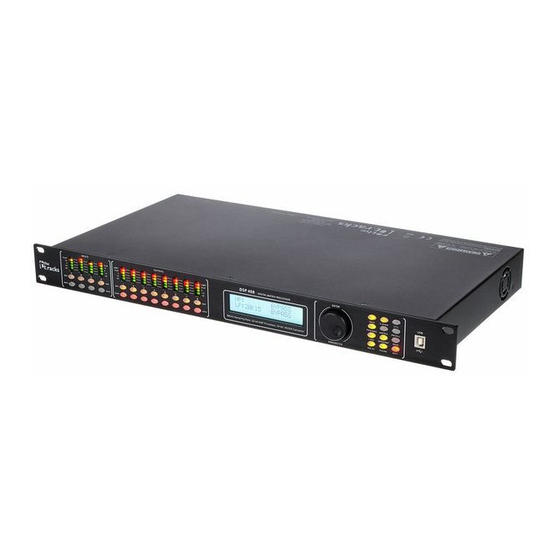
Features Features Digital speaker management system with FIR filter AD/DA converter 32-bit DSP 4 × XLR input sockets 8 × XLR output sockets Comprehensive setting options for optimal sound – Parametric Equalizer – Graphic Equalizer – High- and low-pass filters –... -
Page 9: Installation And Starting Up
Installation and starting up Installation and starting up Unpack and check carefully there is no transportation damage before using the unit. Keep the equipment packaging. To fully protect the product against vibration, dust and moisture during transportation or storage use the original packaging or your own packaging material suitable for transport or storage, respectively. - Page 10 Installation and starting up Configuration example 2 The illustrations show schematically how one device or several devices can be inte‐ grated into a local area network (LAN). Configuration example 3 The illustrations show schematically how a device can be configured via the serial port.
-
Page 11: Connections And Controls
Connections and controls Connections and controls Front panel 1 Display 2 Buttons for direct selection of a parameter. Use [EXIT] to exit the Edit mode. 3 [ENTER / PARAMETER] Rotary switch 4 [EDIT] Buttons for selecting the Edit mode for the respective input channel. The set parameters of the selected channel appear in the display. - Page 12 Connections and controls 9 [MUTE] Buttons for muting or unmuting the respective output channel 10 [MUTE] Buttons for muting or unmuting the respective input channel Rear panel 11 IEC chassis plug with fuse holder for the power supply 12 [POWER] Main switch.
-
Page 13: Operating On The Unit
Operating on the unit Operating on the unit Starting the device Connect the device to the power grid and turn it on with the main switch to start operation. After a few seconds, the display indicates that a reset is in progress. The device is then ready for use. - Page 14 Operating on the unit User presets All device settings can be stored in up to 20 different user presets and recalled when needed. This allows you to easily restore your settings for different rooms or stage setups. Recalling user preset Press [PRESET].
- Page 15 Operating on the unit Settings for the inputs Press the [EDIT] button corresponding to the desired channel. ð The settings menu for the desired channel opens up. The display shows ‘GAIN’ . In the default state of the menu, you can adjust the channel level in a range of -60 dB…+12 dB with the rotary switch.
- Page 16 Operating on the unit Settings for the outputs Press the [EDIT] button corresponding to the desired channel. ð The settings menu for the desired channel opens up. The display shows ‘GAIN’ . In the default state of the menu, you can adjust the channel level in a range of -60 dB…+12 dB with the rotary switch.
- Page 17 Operating on the unit Parameter Button Selection range Meaning ‘MATRIX’ [MATRIX] Assignment selection of input channels to the respective output channel. To each output channel, an input channel or the mix of several input channels can be freely assigned. ‘MIX’ [MATRIX] ‘T’...
-
Page 18: Operating On The Computer
Operating on the computer Operating on the computer Install and start the software. Insert the software CD into the disk drive of your Windows PC and start the installation programme that matches the device version. Follow the instructions of the installation programme to completion. Connect your PC to the device via a USB cable and turn on the device. - Page 19 Operating on the computer Main menu Menu item Meaning ‘File’ Loading user presets and saving them to the PC; Data upload to the PC and data download to the device ‘Link’ Assignment of input to output channels ‘Copy’ Copying parameter settings from one input or output channel to another ‘Lock’...
- Page 20 Operating on the computer ‘Gain’ tab Range Meaning Display area The waveform of input and output channels is graphically displayed. Use the radio buttons ‘Inx’ and ‘Outx’ to set the inputs and outputs to be displayed. Control area Drag the faders with the mouse to adjust the levels for the input and output channels. The ‘Mute’ button mutes or unmutes the respective channel.
- Page 21 Operating on the computer ‘Gate’ tab Range Meaning Display area Shows the current settings of the noise gate for the respective channel, with a symbolic level indi‐ cator symbol appearing next to it for the input channels. The red dot in the curve corresponds to the current signal.
- Page 22 Operating on the computer ‘Comp’ tab Range Meaning Display area Shows the current settings of the compressor function for the respective output channel, with a sym‐ bolic level indicator symbol appearing next to it for all output channels. The red dot in the curve cor‐ responds to the current signal.
- Page 23 Operating on the computer ‘Limit’ tab Range Meaning Display area Shows the current settings of the limiter for the respective channel, with a symbolic level indicator appearing next to it for all channels. Control area Drag the faders with the mouse to set the limiter parameters for all input and output channels: Threshold, attack, ratio, soft knee, release.
- Page 24 Operating on the computer ‘Delay’ tab Range Meaning Display area Shows the set delays for all in and output channels. Control area Drag the faders with the mouse to adjust the delay for the respective channel. Press one of the but‐ tons ‘ms’...
- Page 25 Operating on the computer ‘Matrix’ tab Range Meaning Display area Shows the current interconnection of input to output channels. Input and output channels can be renamed. Click on a functional area (e.g. ‘PEQ’ or ‘DELAY’ ) to open the tab where you can enter the corresponding parameters directly. Control area With a mouse click you can interconnect each input with each output channel.
- Page 26 Operating on the computer ‘In’ tab Range Meaning Display area Use the radio buttons ‘Mag’ or ‘Phase’ to switch the diagram from Cartesian coordinates (level vs. frequency) to polar coordinates (angle vs. frequency). Use the radio button ‘SHOW ALL EQ’ to display the parameters for all nine frequency bands. Control area For each input channel and all nine frequency bands (numbered with ‘PEQ’...
- Page 27 Operating on the computer ‘Out’ tab FIR DSP 408...
- Page 28 Operating on the computer Range Meaning Display area Use the radio buttons ‘ Mag’ or ‘Phase’ to switch the diagram from Cartesian coordinates (level vs. frequency) to polar coordinates (angle vs. frequency). Use the radio button ‘SHOW ALL EQ’ to display the parameters for all nine frequency bands. Control area For each output channel and all nine frequency bands (numbered with ‘PEQ’...
-
Page 29: Technical Specifications
Technical specifications Technical specifications Inputs Type XLR chassis socket (balanced) Level +18 dBu (max.) Impedance 1 MΩ (stereo), 500 kΩ (mono) Outputs Type XLR chassis plug (balanced) Level +20 dBu (max.) Impedance < 500 Ω Frequency response 20 Hz … 20 kHz, –0.3 dBu <... -
Page 30: Plug And Connection Assignment
Plug and connection assignment Plug and connection assignment Introduction This chapter will help you select the right cables and plugs to connect your valuable equipment in such a way that a perfect sound experience is ensured. Please note these advices, because especially in ‘Sound & Light’ caution is indicated: Even if a plug fits into the socket, an incorrect connection may result in a destroyed power amp, a short circuit or ‘just’... -
Page 31: Protecting The Environment
Protecting the environment Protecting the environment Disposal of the packaging material For the transport and protective packaging, environmentally friendly materials have been chosen that can be supplied to normal recycling. Ensure that plastic bags, packaging, etc. are properly disposed of. Do not just dispose of these materials with your normal household waste, but make sure that they are collected for recycling. - Page 32 Notes digital speaker management system...
- Page 33 Notes FIR DSP 408...
- Page 34 Notes digital speaker management system...
- Page 36 Musikhaus Thomann · Hans-Thomann-Straße 1 · 96138 Burgebrach · Germany · www.thomann.de...
Need help?
Do you have a question about the t.racks FIR DSP 408 and is the answer not in the manual?
Questions and answers