Table of Contents
Advertisement
Quick Links
TOMATECH AUTOMATION
COPY RIGHTS
This user manual describes all items concerning the operation of
the system in detail as much as possible. However, it is impractical
to give particular descriptions of all unnecessary and/or unavailable
operations of the system due to the manual content limit, product
specific operations and other causes. Therefore, the operations not
specified herein shall be considered impossible or unallowable.
This user manual is the property of TOMATECH AUTOMATION
CO.,LTD
All rights are reserved. It is against the law for any organization or
individual to publish or reprint this manual without the express
written permission of TOMATECH and the latter reserves the right
to ascertain their legal liability.
TOMATECH(SHENZHEN)AUTOMATION CO.,LIMITED
Add.: 303,No.6 Minhuan Rd. Longhua New Distr. Shenzhen, China
Tel:+86
755 85276656
Web.: www.tomatech-cnc.com
Advertisement
Table of Contents

Summary of Contents for TOMATECH TAC-100XT
- Page 1 All rights are reserved. It is against the law for any organization or individual to publish or reprint this manual without the express written permission of TOMATECH and the latter reserves the right to ascertain their legal liability. TOMATECH(SHENZHEN)AUTOMATION CO.,LIMITED Add.: 303,No.6 Minhuan Rd.
- Page 2 FOREWORD Dear user, We are really grateful for your patronage and purchase of thisTAC-100XT Turning CNC system made by TOMATECH AUTOMATION CO.,LTD The user manual describes the programming, operation, installation and connection of thisTAC-100XT Turning CNC system. Please read it carefully before operation in order to get the safe and effective working.
-
Page 3: Troubleshooting
TOMATECH AUTOMATION ■ Troubleshooting Switch off power supply before troubleshooting or changing components. Troubleshoot and then startup the system when there is short circuit or overload. Do not switch on or off it frequently and an interval is 1 minute at least after the system is powered on again. - Page 4 TOMATECH AUTOMATION Ⅰ Programming TAC-100XT CNC Technical Specification, Product Type, Command and Program Format Ⅱ Operation TAC-100XT CNC Operation Use Ⅲ Installation and Connection TAC-100XT CNC Installation, Connection and Setting Appendix CNC Ladder Function Allocation, Alarm Message Table...
- Page 5 TOMATECH AUTOMATION Safety Responsibility Manufacturer’s safety responsibility —— The manufacturer should be responsible for the cleared or the controlled safety in the design and the structure of the CNC system and the accessories. —— The manufacturer should be responsible for the CNC system and the accessories.
-
Page 6: Table Of Contents
TOMATECH AUTOMATION CONTENTS Ⅰ Programming CHAPTER 1 PROGRAMMING......................1 1.1TAC-1002T Introduction .........................1 1.1.1 Product introduction...................1 1.1.2 Technical specification ..................2 1.1.3 Environment and conditions................4 1.1.4 Power supply ......................5 1.1.5 Guard........................5 1.2 CNC System of Machine Tools and CNC Machine.Tools...................... - Page 7 TOMATECH AUTOMATION Return from subprogram M99..................23 Macro program call M9000~M9999................24 M commands defined by standard PLC ladder diagram..........24 Program stop M00 ......................25 Program optional stop M01 ..................25 Spindle CW, CCW and stop control M03, M04, M05..........26 Cooling control M08, M09....................26...
- Page 8 TOMATECH AUTOMATION 3.11.3 Special cases....................72 3.12 Dwell G04......................74 3.13 Machine Zero Function ..................74 3.13.1 Machine 1st reference point G28 ..............74 3.13.2 Machine 2nd, 3rd, 4th reference point G30............. 75 3.14 Skip Interpolation G31..................77 3.15 Automatic Tool Offset G36, G37................ 79 3.16 Workpiece Coordinate System G50 ..............
- Page 9 TOMATECH AUTOMATION 3.26.2 Transfer and cycle.................... 147 3.27 Metric/Inch Switch....................150 CHAPTER 4 TOOL NOSE RADIUS COMPENSATION (G41, G42) ......152 4.1 Application ......................152 4.1.1 Overview......................152 4.1.2 Imaginary tool nose direction ................152 4.1.3 Compensation value setting................156 4.1.4 Command format ..................... 157 4.1.5 Compensation direction ...................
- Page 10 TOMATECH AUTOMATION 2.2 System Power-off ....................205 2.3 Overtravel Protection ....................206 2.3.1 Hardware overtravel protection................206 2.3.2 Software Overtravel Protection................206 2.4 Emergency Operation....................207 2.4.1 Reset ........................207 2.4.2 Emergency stop.....................207 2.4.3 Feed hold.......................207 2.4.4 Power-off .......................207 CHAPTER 3 MANUAL OPERATION ................209 3.1 Coordinate Axis Move....................209 3.1.1 Manual feed......................209...
- Page 11 TOMATECH AUTOMATION 6.1.3 Searching a character....................226 6.1.4 Inserting a character .....................229 6.1.5 Deleting a character....................230 6.1.6 Altering a character....................230 6.1.7 Deleting a single block...................231 6.1.8 Copying and pasting a block..................232 6.1.9 Canceling and recovering a program..............233 6.1.10 Program save ......................233 6.1.11 Macro program edit....................234...
- Page 12 TOMATECH AUTOMATION 8.1.5 Adjustment of the feedrate, rapid rate ..............258 8.1.6 Spindle speed adjustment..................258 8.2 Running State ......................259 8.2.1 Single block execution...................259 8.2.2 Dry run........................259 8.2.3 Machine lock......................259 8.2.4 MST lock........................260 8.2.5 Block skip ......................260 8.3 MPG Trial-cut......................260 8.3.1 Switching MPG trial-cut mode ................260 8.3.2 Command speed in MPG trial-cut mode..............261...
- Page 13 TOMATECH AUTOMATION 11.3.3 Operation path selection ..................287 11.3.4 Format of data backup/resume file...............288 11.3.5 Level explanation of data backup/resume operation..........289 11.4 Notes........................289 CHAPTER 12 COMMUNICATION.................290 12.1TAC-100XT Communication Software TOMATECHComm......................290 12.1.1 TOMATECHComm’s system (PC) requirements........................290 12.1.2 Software interface....................290 12.1.3 Receiving files (CNC→PC).................291 12.1.4 Sending files (CNC→PC)..................293...
- Page 14 2.3.2 Signal explanation ..................... 315 2.4 Spindle Interface....................316 2.4.1 Spindle interface definition................. 316 2.4.2 Connection to inverter ..................317 2.5TAC-1002T/TAC-100XT-V being Connected with PC ..........317 2.5.1 Communication interface definition ..............317 2.5.2 Communication interface connection..............317 2.6 Power Interface Connection .................318 2.7 I/O Interface Definition ..................318...
- Page 15 TOMATECH AUTOMATION 2.8.22 Tri-color Lamp................... 365 2.8.23 Extended M Function…………………………………………………………...365 2.8.24 HOLD Control…………………………………………………………………..367 2.8.25 Gear/tool number display ………………………………………………………367 2.9 Commonly Use Symbol of Electricity Drawing..........367 CHAPTER 3 PARAMETERS................369 Contents 3.1 Parameter Description (by sequence)............369 3.1.1 Bit parameter ....................369 3.1.2 Data parameter....................378 3.1.3 PLC parameters(standard PLC definition)...
- Page 16 TOMATECH AUTOMATION 4.8 Tool Post Debugging.................421 4.9 Step/MPG Adjustment................422 CHAPTER 5 DIAGNOSIS MESSAGE ............423 5.1 CNC Diagnosis ..................423 5.1.1 I/O status and data diagnosis message..........423 5.1.2 CNC motion state and data diagnosis message ......... 423 5.1.3 Diagnosis keys..................424 5.1.4 Others....................425 5.2 PLC State....................425...
- Page 17 TOMATECH AUTOMATION Appendix Ⅴ Outline Dimension of Accessional Panel AP03........................453 Appendix Ⅵ Outline Dimension of I/O deconcentrator MCT01A......................454 Appendix Ⅶ Outline Dimension of I/O deconcentrator MCT02 ......................454 Appendix Ⅷ Delivery standard parameter .......................455 Appendix Ⅸ Alarm list........................462 Appendix Ⅹ Operation...
-
Page 18: Chapter 1 Programming
CHAPTER 1 PROGRAMMING 1.1 TAC-100XT Introduction 1.1.1 Product introduction TAC-100XT is a new upgraded software, its software, hardware based on TOMATECH, structure horizontal and vertical, matched with 8.4 inch color LCD, with 5 feed axes (including C axis), 2 analog spindles, least input increment 0.1μm. It uses the graphic interface, friendly human-machine operation window. -
Page 19: Technical Specification
TOMATECH AUTOMATION Max. speed 60m/min(up to 24m/min in 0.1μm) Adapting to the servo spindle to realize the spindle continuously positioning, rigid tapping, and the rigid thread machining Built-in multi PLC programs, and the PLC program currently running can be selected... - Page 20 TOMATECH AUTOMATION 2-channel 0V~10V analog voltage output, two-spindle control 1-channel spindle encoder feedback, spindle encoder line can be set ( 100p/r~5000p/r) Transmission ratio between encoder and spindle:(1~255):(1~255) Spindle speed: it is set by S or PLC, and speed range: 0r/min~9999r/min Spindle override: 50%~120% 8 grades tune...
- Page 21 TOMATECH AUTOMATION software serial upgrade USB:U file operation, U file directly machining, PLC program, system software U upgrade Safety function Emergency stop Hardware travel limit Software travel check Data backup and recovery Ⅰ Programming...
-
Page 22: Environment And Conditions
Altitude ≤1000m ≤1000m Chapter 1 Programming Ⅰ Programming 1.1.4 Power supply TAC-100XT can normally run in the following AC input power supply. Voltage: within(0.85~1.1)×200V (rated AC input voltage); Frequency: 49Hz~51Hz continuously changing 1.1.5 Guard TAC-100XT guard level is not less than IP20. - Page 23 Thereof, the motion control systems and logic control systems are the main of CNC machine tools. TAC-100XT Turning Machine CNC system has simultaneously motion control and logic control function to control two axes of CNC machine tool to move, and has nested PLC function.
- Page 24 TOMATECH AUTOMATION Programming is a course of workpiece contours, machining technologies, technology parameters and tool parameters being edit into part programs according to special CNC programming G codes. CNC machining is a course of CNC controlling a machine tool to complete machining of workpiece according requirements of part programs.
-
Page 25: Programming.fundamentals
Sketch map of CNC turning machine is as follows: Fig. 1-3 TAC-100XT uses a rectangular coordinate system composed of X, Z axis. X axis is perpendicular with axes of spindle and Z axis is parallel with axes of spindle; negative directions of them approach to the workpiece and positive ones are away from it. -
Page 26: Machine Coordinate System, Machine Zero And Machine Reference Point
TOMATECH AUTOMATION 1.3.2 Machine coordinate system, Machine Zero and machine reference point Machine tool coordinate system is a benchmark one used for CNC counting coordinates and a fixed one on the machine tool. Machine tool zero is a fixed point which position is specified by zero switch or zero return switch on the machine tool. -
Page 27: Interpolation Function
TAC-100XT X and Z axis are link axes and 2 axes link CNC system. The system possesses linear, circular and thread interpolation function. -
Page 28: Absolute Programming And Incremental Programming
TOMATECH AUTOMATION thread cutting. For thread interpolation, the feed axis rotates along with the spindle, the long axis moves one pitch when the spindle rotates one rev, and the short axis and the long axis directly interpolate. Example: Fig. 1-7 …... -
Page 29: Diameter Programming And Radius Programming
TOMATECH AUTOMATION program, which is called the compound programming. Example: A→B linear interpolation Fig.1-8 Absolute programming: G01 X200 Z50; Incremental programming: G01 U100 W-50; Compound programming: G01 X200 W-50; or G01 U100 Z50 Note: When there are command address X/ U or Z/ W at the same time, X/Z command value is valid. -
Page 30: General Structure Of A Program
TOMATECH AUTOMATION User needs to compile part programs (called program) according to command formats of CNC system. CNC system executes programs to control the machine tool movement, the spindle starting/stopping, the cooling and the lubricant ON/OFF to complete the machine of workpiece. - Page 31 TOMATECH AUTOMATION Word A word is the basic command unit to command CNC system to complete the control function,composed of an English letter (called command address) and the following number (operation command with/without sign). The command address describes the meaning of its following operation command and there may be different meaning in the same command address when the different words are combined together.
- Page 32 TOMATECH AUTOMATION...
- Page 33 TOMATECH AUTOMATION Block A block which is basic unit of CNC program consists of a sequence of words, ending with “;” or“*” . There is the character “;” or “*” between blocks. “;” is used to separate blocks in the manual as follows: One block may be with a number of words or only with “;...
-
Page 34: Main Program And Subprogram
TOMATECH AUTOMATION Character for block skip Insert “/” in the front of block and startup when some block cannot be executed (cannot be deleted), and the system skips the block and executes the next one. The block with “/” in the front of it is executed if the block skip switch is not started. - Page 35 TOMATECH AUTOMATION the cursor is located in the heading of the first block and can be moved in Edit mode. In the run stop state in Auto mode, the program starts to run by the cycle start signal ( is pressed or external cycle start signal)from a block pointed by current cursor, usually blocks are executed one by one according to their programming sequence, the program stops running till executing M02 or M30.
-
Page 36: Execution Sequence Of Word
TOMATECH AUTOMATION executing M99(if M99 specifies a target block number, the system returns to it to run) after the subprograms or macro programs run completely; The system return to the first block to run and the current program is executed repetitively when M99 is executed in a main program. -
Page 37: Chapter 2 Mstf Command
TOMATECH AUTOMATION CHAPTER 2 MSTF COMMAND 2.1 M (Miscellaneous Function) M command consists of command address M and its following 1~2 or 4 bit digits, used controlling the flow of executed program or outputting M commands to PLC. M98, M99, M9000~M9999 is executed by NC separately and NC does not output M commands to PLC. -
Page 38: Subprogram Call M98
TOMATECH AUTOMATION program (whether the cursor return to the start of program or not is defined by parameters). If No.005 Bit 4 is set to 0, the cursor does not return to the beginning of program, and the cursor returns immediately after the program is executed completely when No.005 Bit 4 is set to 1. -
Page 39: Macro Program Call M9000~M9999
TOMATECH AUTOMATION Called subprogram number ( 0000 ~ 9999 ) . The leading zero of subprogram number can be omitted when the calling times is not input; the subprogram number must be with 4 digits when the calling times is input.. -
Page 40: M Commands Defined By Standard Plc Ladder Diagram
TOMATECH AUTOMATION level (machine manufacturer) when editing O9000~O9999, and macro programs calling commands are executed to call with 3~5 operation level. M9000~M9999 are invalid in MDI mode. M commands defined by standard PLC ladder diagram Other M commands are defined by PLC except for the above-mentioned ones(M02, M30, M98, M99, M9000~M9999). -
Page 41: Program Optional Stop M01
TOMATECH AUTOMATION Command function: After M00 is executed, the program stops and the system displays “Pause”, and then the program continuously runs after the cycle start key is pressed. Program optional stop M01 Command format: M01 or M1 Ⅰ Programming Command function: in AUTO, MDI mode, it is valid. -
Page 42: Spindle Clamped/Released M20, M21
TOMATECH AUTOMATION Command format:M14; M15; Command function: M14: spindle is in the position control mode from speed control mode; M15:spindle is in speed control mode from the position control mode. Note: Refer to time sequence and logic of M14, M15 defined by standard PLC ladder in Ⅲ... -
Page 43: Spindle Function
TOMATECH AUTOMATION Command format:M5n;(n=0~8) Command function:M50:cancel orientation state; M5n(n=0~8):the spindle oriented to No. n point. Note: Refer to time sequence and logic of M50~M58 defined by standard PLC ladder in Ⅲ INSTALLATION & CONNECTION. The 2nd spindle rotation CCW, rotation CW , stop M63, M64, M65 Command format: M63;... -
Page 44: Constant Surface Speed Control G96, Constant Rotational Speed Control G97
TOMATECH AUTOMATION When executing S00, S1~S4 output are cancelled and only one of S1~S4 is valid at the same time. 2.2.2 Spindle speed analog voltage control Spindle speed is controlled by analog voltage when No.001 BIT4 is set to 1. - Page 45 TOMATECH AUTOMATION rotational speed control is valid and the spindle speed is defined (r/min). G96 is modal G code. If the current modal is G97, G97 cannot be input. Command format: G50 S__; (S0000~S9999, the leading zero can be omitted.) Command function: define max.
- Page 46 TOMATECH AUTOMATION end point in the program block. In G96 (constant surface speed control), Z coordinates axis of workpiece system must consist with the axes of spindle (rotary axis of workpiece), otherwise, there is different between the actual surface speed and the defined one.
-
Page 47: Spindle Override
OPERATION. 2.2.5 Multiple spindle control function TAC-100XT can control up to two analog spindles. One S code is used to command one of them which are selected by PLC signal and which have the gear change function. BecauseTAC-1002T has only one spindle encoder interface, the 2 spindle has no encoder feedback and the spindle speed is not displayed. -
Page 48: Cs Contour Control Function
TOMATECH AUTOMATION control function. The spindle control has several methods which are set by MSI(№196#7)as follows: Multiple spindle control method A When SWS1 signal selects the 1 spindle, SIND signal is used to determine that the spindle analog voltage is controlled by PLC or CNC, R011 to R121 signals are used to set the spindle analog voltage. -
Page 49: Tool Function
TOMATECH AUTOMATION 2.3 Tool Function 2.3.1 Tool control T functions ofTAC-1002T: automatic tool change and executing tool offset. Control logic of automatic tool change is executed by PLC and tool offset is executed by NC. Command format: Command function: The automatic tool post rotates to the target tool number and the tool offset of tool offset number commanded is executed. - Page 50 TOMATECH AUTOMATION the tool length compensation is changed. Example: When the state parameter No.004 Bit4 is set to 0 and X tool length compensation value is 10mm, the external diameter of workpiece is 10mm; when No. 004 is set to 1 and X tool length compensation value is 10mm, the external diameter of workpiec is 20mm.
- Page 51 TOMATECH AUTOMATION Ⅰ Programming Fig. 2-7 Tool traversing mode Fig. 2-8 Modifying the coordinates mode In Edit and Auto mode, a sole T word in executing tool offset (it is not with the motion command in the same block) is relative to No.004 BIT3 setting (as Fig.2-6 and Fig.2-7).
- Page 52 TOMATECH AUTOMATION and a sole T command is executed, the tool offset number is displayed in poor, which is cleared out(tool offset number is still displayed in poor when tool offset is not executed for one axis, the previous bit of tool offset number is for X axis tool compensation and the next one is for Z axis tool compensation) after executing tool offset.
-
Page 53: Tool Life Management
TOMATECH AUTOMATION 2.3.2 Tool life management 1. Starting tool life management function The state parameter No.002 Bit0 (TLIF) is the market whether the tool life management function is valid or not, the corresponding tool life management window is not displayed when it is invalid. - Page 54 TOMATECH AUTOMATION The current window displays the life management data of current used tool life management and defined tool groups. The window is shown below: Current tool state: display the current used tool life management data; Tool number: current used tool and tool compensation number;...
- Page 55 TOMATECH AUTOMATION Command format: G11 Command function: cancel the tool life management data input mode Programming L_: tool life data, the specified value can be time or number of times according to the different count N value Note 1: The tool group numbers specified by P may not be the continuous, but it is better to gradually increase the sequence number to easily search the tool group number.
- Page 56 TOMATECH AUTOMATION mode, parameter switch ON and 3-level operation limit. A. alter data: In tool compensation -> tool life window, press to move the tool to the life position, input directly data, such as 500, press to confirm the input. Press complete data input (tool offset, life) .
- Page 57 TOMATECH AUTOMATION After insert b)Insert the middle and the previous sequence number moves backward. Before insert...
- Page 58 TOMATECH AUTOMATION After insert c)Insert behind Before insert...
- Page 59 TOMATECH AUTOMATION After insert C. Delete data: a) Delete data in all groups. In tool compensation-> tool life window, press to delete all defined data. Before operation After operation...
- Page 60 TOMATECH AUTOMATION b) Delete data in any group ――>input serial number[02]――> Press Before operation After deletion...
- Page 61 TOMATECH AUTOMATION c) Delete any serial number in the current page(the parameter switch is ON) ――>input serial number[04]――> Programming Press Before deletion After deletion...
- Page 62 TOMATECH AUTOMATION 4. Tool life function use Command format: Txx99: end of current used tool group, start the tool and execute the life management in group. Txx88: cancel the tool offset in XX group Two examples are as follows: Application example: O0000 (O0000) …...
- Page 63 TOMATECH AUTOMATION determined by No.002 Bit3 (MDITL). 002 MDITL MDITL=0 Tool life management is invalid in MDI mode. MDITL=1 Tool life management is valid in MDI mode. The tool life count has two methods including time and number of times.
- Page 64 TOMATECH AUTOMATION 6. G, F signals relevant to tool life function a) Tool change signal TLCH(F064#0) [Type] output signal [Function] inform PLC that the last tool life ends of in this group [Output condition] the signal is set to 1, the last tool life in one group ends, all other tool life ends.
-
Page 65: Chapter 3 Gcommands
TOMATECH AUTOMATION CHAPTER 3 G COMMANDS 3.1 Commands G command consists of command address G and its following 1~2 bits command value, used for defining the motion mode of tool relative to the workpiece, defining the coordinates and so on. Refer to G commands as Fig. 3-1. -
Page 66: Modal, Non-Modal And Initial Mode
TOMATECH AUTOMATION 3.1.1 Modal, non-modal and initial mode G commands are divided into group 00, 01, 02, 03, 06, 07, 16, 21. After G commands are executed, their defined functions and states are valid until they are changed by others in the same group, which commands are called modal G commands. -
Page 67: Omitting Words
TOMATECH AUTOMATION 3.1.2 Omitting words To simplify the programming, their command values are reserved after executing words in Table 3-2. If the words are contained in the previous blocks, they cannot be input when the words are used with the same values and definitions in the following blocks. -
Page 68: Related Definitions
TOMATECH AUTOMATION Example 1: O0001; G0 X100 Z100; (rapid traverse to X100 Z100; the modal G0 is valid) X20 Z30; (rapid traverse to X20 Z30; the modal G0 is not input) G1 X50 Z50 F300; (linear interpolation to X50 Z50, feedrate 300mm/min; the modal G1 is valid) X100;... - Page 69 TOMATECH AUTOMATION X, U, Z, W range: ± 99999999× least input increment; Can omit one or all command addresses X(U), Z(W). The coordinate values of starting point and end point are the same when omitting one command address; the end point and the starting point are in the same position when all are omitted.
-
Page 70: Linear Interpolation G01
TOMATECH AUTOMATION G0 X20 Z25; (absolute programming) G0 U-22 W-18; (incremental programming) G0 X20 W-18; (compound programming) G0 U-22 Z25; (compound programming) 3.3 Linear Interpolation G01 Command format: G01 X(U) _ Z(W) _ F_; Command function: The movement path is a straight line from starting point to end point as Fig.3-3. - Page 71 TOMATECH AUTOMATION 3.4 Circular Interpolation G02, G03 Command function: G02 movement path is clockwise (rear tool post coordinate system)/counterclockwise (front tool post coordinate system) arc from starting point to end point as Fig. 3-5. G03 movement path is counterclockwise (rear tool post coordinate system/clockwise (front tool post coordinate system) arc from starting point to end point as Fig.
- Page 72 TOMATECH AUTOMATION I: X difference value between circle center and starting point of arc in radius; K: Z difference value between circle center and starting point of arc; Center point of arc is specified by address I, K which separately corresponds to X, Z, I, K expresses the vector (it is the increment value) from starting point to center point of arc as following figure;...
- Page 73 TOMATECH AUTOMATION R is valid and I, K are invalid when they are input at the same time. R value must be equal to or more than half distance from starting point to end point, and The system alarms if the end point is not on the arc defined by R command;...
-
Page 74: Plane Selection G17~G19
TOMATECH AUTOMATION Program: O0001 N001 G0 X40 Z5; (Rapidly traverse) N002 M03 S200; (Start spindle) N003 G01 X0 Z0 F900; (Approach workpiece) N005 G03 U24 W-24 R15; (Cut R15 arc) N006 G02 X26 Z-31 R5; (Cut R5 arc) N007 G01 Z-40; (Cut φ26) N008 X40 Z5;... -
Page 75: Chamfering Function
TOMATECH AUTOMATION Diameter or radius programming: currently, because there is only one bit parameter No 1.2 to select the diameter or the radius programming and is valid to only X axis, Z and Y axis use the only radius programming in G2, G3, and X axis is selected by the parameter;... - Page 76 TOMATECH AUTOMATION C. Circular to circular Command format: G02/G03 X(U)_ Z(W)_ R_ L_; G02/G03 X(U)_ Z(W)_ R_; G02/G03 X(U)_ Z(W)_ I_ K_ L_; G02/G03 X(U)_ Z(W)_ I_ K_; Command function: insert one straight line between two circular interpolation blocks. Programming D.
-
Page 77: Circular Chamfering
TOMATECH AUTOMATION Command function: insert one straight line block between circular and linear interpolation block. 3.11.2 Circular chamfering Circular chamfering: insert one circular between linear contours, circular contours, linear contour and circular contour, the circular and the contour line are transited by the tangent. - Page 78 TOMATECH AUTOMATION Command function: insert one circular between linear and circular, the inserted circular is tangent to the linear and the circular, and the radius is the data behind the command address D. C. Circular to circular Command format: G02/G03 X(U)_ Z(W)_ R_ D_;...
- Page 79 TOMATECH AUTOMATION D. Circular to linear Command format: G02/G03 X(U)_ Z(W)_ R_ D_; G01 X(U)_ Z(W)_; G02/G03 X(U)_ Z(W)_ I_ K_ D_; G01 X(U)_ Z(W)_; Command function: insert one circular block between the circular and the linear, the inserted circular block is tangent to the circular and the linear, and the radius is the data behind the command address D.
- Page 80 TOMATECH AUTOMATION The chamfering linear length is L, CNC alarms when other end of the caculated chamfering linear is not in the interpolation linear(in the extension line of the interpolation linear). 2) Circular chamfering A. The circular chamfering function is invalid when two interpolation straight lines are in the same block.
- Page 81 TOMATECH AUTOMATION Programming The circular chamfering function is valid when the circular tangency is as follows: 3.12 Dwell G04 Command format: G04 P__ ; or G04 X__ ; or G04 U__ ; or G04; Command function: each axis stops the motion, the modal of G commands and the reserved data, state are not changed, and execute the next block after dwelling the defined time.
- Page 82 TOMATECH AUTOMATION G28 is non-modal. X, Z, Y: absolute coordinates of middle point; U, W, V: Z absolute coordinates of middle point; W: Difference value of absolute coordinates between middle point and starting point in Z direction. Omit all or one of X(U), Z(W) as follows: Running path(as Fig.
- Page 83 The coordinates of machine reference point are No.120, No.121 setting value. Executing machine zero return is considered to executing the machine reference point return. TAC-100XT has machine 2 reference point functions. Use separately No.122~ No.127...
- Page 84 TOMATECH AUTOMATION G30 Pn X(U) Z(W) X and Z return to the machine nth reference point simultaneously Note 1: n in the above table is 2, 3 or 4; Note 2: Do not check the deceleration, zero signal when you execute the machine 2 reference point.
- Page 85 TOMATECH AUTOMATION 3.14 Skip Interpolation G31 Command format: G31 X(U)_ Z(W)_ F_; Command function: in executing the command, when the outside skip signal (X3.5) is input, the system stops the command to execute the next block. The function is used to the dynamic measure (such as milling machine), toolsetting measure and so on of workpiece measure.
- Page 86 TOMATECH AUTOMATION Fig. 3-15: Program: G31 Z200 F100 G01 X100 Z300 Ⅰ Programming b. Signals relevant to G31 Skip signal: SKIP:G6.6 Type: input signal Function: G6.6 ends the skip cutting. I.e. in a block containing G31, the skip signal becoming the absolute coordinate position of “1” is to be stored in the macro variable (#5011~#5015 separately corresponds to X, Z, Y)
- Page 87 TOMATECH AUTOMATION system is created again (using G50). Command specifications: G50 is non-modal; X: New absolute coordinates of current position in X direction; U: Different value between the new absolute coordinates of current position in X direction And the absolute coordinates before executing commands;...
- Page 88 TOMATECH AUTOMATION 3.18 Workpiece Coordinate System G54~G59 Command format: G54 workpiece coordinate system 1 G55 workpiece coordinate system 2 G56 workpiece coordinate system 3 G57 workpiece coordinate system 4 G58 workpiece coordinate system 5 G59 workpiece coordinate system 6 Command function: one of G54~G59 is specified, one of workpiece coordinate system 1~6 is selected.
- Page 89 TOMATECH AUTOMATION Absolute coordinates after zero return is(0,0);EXOF=(0,0) ; ZOFS1=(-10,-10); Absolute coordinate values after zero return in G54: 0 - (-10 + 0) = 10; Example 2: Absolute coordinate values after zero return:(20,20);EXOF=(5,5) ; ZOFS2=(10, 10); Absolute coordinate values after zero return in G55: 20 - (10 + 5) = 5;...
- Page 90 TOMATECH AUTOMATION systems, which are shown below: Ⅰ Prog ramming 3.19 Fixed Cycle Command To simplify programming, the system defines G command of single machining cycle with block to complete the rapid traverse to position, linear/thread cutting and rapid traverse to...
- Page 91 TOMATECH AUTOMATION ① X rapidly travrses from starting point to cutting starting point; ② Cutting feed (linear interpolation) from the cutting starting point to cutting end point; ③ X executes the tool retraction at feedrate (opposite direction to the above- mentioned), and return to the position which the absolute coordinates and the starting point are the same;...
- Page 92 TOMATECH AUTOMATION Fig. 3-19 Example: Fig. 3-20, rod Φ125×110...
- Page 93 TOMATECH AUTOMATION Fig. 3-20 Ⅰ Programming 3.19.2 Radial cutting cycle G94 Command format: G94 X(U) __ Z(W) __ F__; (face cutting) G94 X(U) __ Z(W) __ R__ F__; (taper face cutting) Command function: From starting point, the cutting cycle of cylindrical surface or taper surface is completed by radial feeding(X) and axial (Z or X and Z) cutting.
- Page 94 TOMATECH AUTOMATION Fig. 3-21 ogra mming Fig. 3-22 Cutting path: Relative position between cutting end point and starting point with U, W is shown in Fig.3-23:...
- Page 95 TOMATECH AUTOMATION Fig. 3-23 Ⅰ Programming Example: Fig. 3-24, rod Φ125×112...
-
Page 96: Caution Of Fixed Cycle Commands
TOMATECH AUTOMATION Fig. 3-24 3.19.3 Caution of fixed cycle commands 1) After X(U) , Z(W) , R are executed in the canned cycle command, their command values are value if X(U) , Z(W) ,R are not redefined by executing a new canned cycle commands. -
Page 97: Multiple Cycle Commands
TOMATECH AUTOMATION N010 G90 X20.0 Z10.0 F400; N011 ; (execute G90 one time repetitively) … 4) Pause or single block is executed in G90, G94, the single block stops after the tool moves end point of current path. (Outer cutting Φ120)... - Page 98 TOMATECH AUTOMATION to the formed roughing of non-formed rod. Relevant definitions: Finishing path: The above-mentioned Part 3 of G71(ns~nf block)defines the finishing path, and the starting point of finishing path (starting point of ns block)is the same these of starting point and end point of G71, called A point; the first block of finishing path(ns block)is used for X rapid traversing or tool infeed, and the end point of finishing path is called to B point;...
- Page 99 TOMATECH AUTOMATION S, T,F functions of M, S, T, F blocks are invalid in G71, and they are valid in G70 finishing blocks. Type I: 1)Execution process: (Fig. 3-25) ① X rapidly traverses to A’ from A point, X travel is Δu, and Z travel is Δw;...
- Page 100 TOMATECH AUTOMATION 2)Coordinate offset direction with finishing allowance: Δu, Δw define the coordinate offset and cut-in direction in finishing, and their sign symbol are as follows Fig. 3-26: B→C for finishing path, B’→C’ for roughing path and A is the tool start-up point.
- Page 101 TOMATECH AUTOMATION Fig. 3-26-2(type Ⅱ) 3)The first tool cutting need not the vertical: the machining can be executed when Z is the monotonous change shape as follows: rogramming Fig. 3-26-3 4)After the turning, the system should execute the tool retraction, the retraction travel is specified by R(e)or No.
- Page 102 TOMATECH AUTOMATION Fig. 3-26-5(typeⅡ) Notes: ● ns block is only G00, G01. When the workpiece is type II, the system must specify the two axes X(U) and Z(W), and W0 must be specified when Z does not move; ● For type II, only X finishing allowance can be specified; when Z finishing allowance is specified, the whole machining path offsets, and it can be specified to 0;...
- Page 103 TOMATECH AUTOMATION the system has executed end point of current path; ● △d,△u are specified by the same U and different with or without being specified P, Q commands; ● G71 cannot be executed in MDI, otherwise, the system alarms;...
-
Page 104: Radial Roughing Cycle G72
TOMATECH AUTOMATION 3.20.2 Radial roughing cycle G72 Command function: G72 is divided into three parts: ⑴ 1st blocks for defining the travels of tool infeed and tool retraction, the cutting speed, the spindle speed and the tool function in roughing;... - Page 105 TOMATECH AUTOMATION offset corresponds separately to A’, B’, C’ point of roughing path, and the final continuous cutting path of G72 is B’→C’ point. Δd: it is Z cutting in roughing, its value: 0.001~99.999(unit: mm/inch) without sign symbol, and the direction of tool infeed is determined by ns block traverse direction. the specified value Δd is reserved and the data value is switched to the corresponding value to save to...
- Page 106 TOMATECH AUTOMATION Programming Fig. 3-28 Command specifications: ● ns~nf blocks in programming must be followed G72 blocks. If they are in the front of G72 blocks, the system automatically searches and executes ns~nf blocks, and then executes the next program following nf block after they are executed, which causes the system executes ns~nf blocks repetitively;...
- Page 107 TOMATECH AUTOMATION ● The tool retraction point should be high or low as possible to avoid crashing the workpiece. ogramming Coordinate offset direction with finishing allowance: Δu, Δw define the coordinate offset and its direction of cut-in in finishing, and their sign symbol are as follows Fig.
-
Page 108: Closed Cutting Cycle G73
TOMATECH AUTOMATION Program: O0005; G00 X176 Z10 M03 S500 (Change No.2 tool and execute its compensation, spindle CW rotation with 500 r/min) G72 W2.0 R0.5 F300; (Tool infeed 2mm, tool retraction 0.5mm) G72 P10 Q20 U0.2 W0.1; (Roughing a--d,X roughing allowance 0.2mm and Z 0.1mm) Ⅰ... - Page 109 TOMATECH AUTOMATION block of finishing path(ns block)is called B point; the end point of finishing path(end point of nf block) is called C point. The finishing path is A→B→C. Roughing path: It is one group of offset path of finishing one, and the roughing path times are the same that of cutting.
- Page 110 TOMATECH AUTOMATION compared to A. Δw>0,it is the offset of the last X positive roughing path compared to finishing path. The system defaults Δw=0 when W(Δw) is not input, i.e. there is no Z finishing allowance for roughing cycle. F: Feedrate; S: Spindle speed; T: Tool number, tool offset number.
- Page 111 TOMATECH AUTOMATION Fig. 3-31 G73 path Command specifications: ● ns~nf blocks in programming must be followed G73 blocks. If they are in the front of G73 blocks, the system automatically searches and executes ns~nf blocks, and then executes the next program following nf block after they are executed, which causes the system executes ns~nf blocks repetitively.
- Page 112 TOMATECH AUTOMATION Coordinate offset direction with finishing allowance: Δi, Δk define the coordinates offset and its direction of roughing; Δu, Δw define the coordinate offset and the cut-in direction in finishing, and their sign symbols are as follows Fig. 3-32: A is tool start-up point, B→C for workpiece contour, B’→C’...
-
Page 113: Finishing Cycle G70
TOMATECH AUTOMATION Fig.3-34 3.20.4 Finishing cycle G70 Command format: G70 P(ns) Q(nf) ; Command function: The tool executes the finishing of workpiece from starting point along with the finishing path defined by ns~nf blocks. After executing G71, G72 or G73 to roughing, execute G70 to finishing and single cutting of finishing allowance is completed. -
Page 114: Axial Grooving Multiple Cycle G74
TOMATECH AUTOMATION position of ns, nf block in G70~G73 blocks are as follows: Command specifications: ● ns~nf blocks in programming must be followed G70 blocks. If they are in the front of G71 blocks, the system automatically searches and executes ns~nf blocks, and then executes the next program following nf block after they are executed, which causes the system executes ns~nf blocks repetitively. - Page 115 TOMATECH AUTOMATION and radial tool infeed are defined by relative position between end point X(U) Z(W) and starting point of cutting. G75 is used for machining radial loop groove or column surface by radial discontinuously cutting, breaking stock and stock removal.
- Page 116 TOMATECH AUTOMATION ① Axial (Z) cutting feed △k from the starting point of axial cutting cycle, feed in Z negative direction when the coordinates of cutting end point is less than that of starting point in Z direction, otherwise, feed in Z positive direction;...
-
Page 117: Radial Grooving Multiple Cycle G75
TOMATECH AUTOMATION Command specifications: ● The cycle movement is executed by Z(W) and P(Δk) blocks of G74, and the movement is not executed if only “G74 R(e) ; ” block is executed; ● Δd and e are specified by the same address and whether there are Z(W) and P(Δk) word or not in blocks to distinguish them;... - Page 118 TOMATECH AUTOMATION cycle: Tool infeeds from starting point in radial direction, retracts, infeeds again, and again and again, and last tool retracts in axial direction, and retracts to position in radial direction, which is called one radial cutting cycle; tool infeeds in axial direction and execute the next radial cutting cycle;...
- Page 119 TOMATECH AUTOMATION 9999999(IS_B)/0<Δk≤ 99999999(IS_C)(unit: least input increment, without sign symbol).. R(Δd):Axial (Z) tool retraction clearance after cutting to end point of radial cutting, its range:0~99999999×least input increment(unit: mm/inch, without sign symbol). The system defaults the tool retraction clearance is 0 after the radial cutting end point is completed when R(Δd) is omitted.
- Page 120 TOMATECH AUTOMATION radial cutting cycle is not the last one, execute ⑥; if it is the previous one before the last radial cutting cycle, execute ⑦; ⑥ Axial(X) rapid tool infeed, and it direction is opposite to ④ retract tool. If the end point...
-
Page 121: Thread Cutting Commands
M30; (End of program) 3.21 Thread Cutting Commands TAC-100XT CNC system can machine many kinds of thread cutting, including metric/inch single,multi threads, thread with variable lead and tapping cycle. Length and angle of thread run-out can be changed, multiple cycle thread is machined by single sided to protect tool and improve smooth finish of its surface. - Page 122 TOMATECH AUTOMATION Execute the end face thread cutting when X coordinates of starting point and end point are the same one(not input Z or W); Execute the cutting taper thread when X and Z coordinates of starting point and end point are different;...
- Page 123 TOMATECH AUTOMATION Fig. 3-38 G32 path Notes: ● J, K are modal. The thread run-out is previous J, K value when they are omitted in the next block in continuous thread cutting. Their mode are cancelled when no thread cutting are executed;...
-
Page 124: Thread Cutting With Variable Lead G34
TOMATECH AUTOMATION G32 X50 W-75 F2.0; (Second taper thread cutting ) G00 X55; (Tool retraction) W75 ; (Z returns to the starting point) M30; 3.21.3 Thread cutting with variable lead G34 Command format:G34 X(U)__ Z(W)__ F(I)__ J__ K__ R__ ;... - Page 125 TOMATECH AUTOMATION Use macro variables to simplify programming when G34 is used many times. δ1 = 4mm,δ2 =4mm, total cutting depth 4mm, total cutting cycle 15 times; first tool infeed 0.8mm, gradual decreasing cutting every time 0.2mm, min. infeed 0.2mm.
-
Page 126: Z Thread Cutting G33
TOMATECH AUTOMATION Cutting infeed: #100=#102 Tool infeed Variable pitch cutting Tool retraction Z returns to starting point Decreasing of cutting feed again: #101=#100-0.2 Assignment again #102=#101 Infeed: Jump to block N20 when #102≦0.2mm Unconditionally jump to block N10 Min. infeed: #102=0.2... - Page 127 TOMATECH AUTOMATION Example: Fig. 3-89, thread M10×1.5 Program O0011; G00 Z90 X0 M03; Start spindle G33 Z50 F1.5; Tap cycle M03 Start spindle again G00 X60 Z100; Machine continuously Note 1: Before tapping, define rotation direction of spindle according to tool rotating. The spindle stops rotation after the tapping is completed and the spindle is started again when machining thread continuously.
- Page 128 TOMATECH AUTOMATION P: Pause time (ms) when tapping to the hole bottom F(I):Thread lead, F(I)> 0 right-hand tapping, F(I)< 0 left-hand tapping K: Repetitive count of tapping. When the incremental programming is used to the tapping hole position, the tapping is performed in the different hole position M: Used to clamp the graduation spindle.
- Page 129 TOMATECH AUTOMATION When the block for rigid tapping specifies M code used to clamp the spindle, Mβ is output. Note: α value is set in №170, β=α+1, so, these corresponding M codes in PLC are executed. Rigid tapping sequence Taking example of G84 right-hand tapping, explain the creation, execution and cancellation of rigid tapping.
-
Page 130: Thread Cutting Cycle G92
TOMATECH AUTOMATION Notes: ● In rigid tapping, when the tapping direction is changed(i.e. G84 and G88 are switched),the system specifies again the hole bottom position of the tapping, otherwise, the unexpected result rises; ● The rigid tapping G command is in Group 01, it is cancelled temporarily in the rigid tapping state, and then is recovered it after the tapping is done;... - Page 131 TOMATECH AUTOMATION Z reaches to end point of cutting as Fig. 3-44. Command specifications: G92 is modal; Starting point of cutting: starting position of thread interpolation; End point of cutting: end position of thread interpolation; X: X absolute coordinate of end point of cutting, unit: mm;...
- Page 132 TOMATECH AUTOMATION Fig. 3-45 The system can machine one thread with many tool infeed in G92, but cannot do continuous two thread and end face thread. Definition of thread pitch in G92 is the same that of G32, and a pitch is defined that it is a moving distance of long axis(X in radius) when the spindle rotates one rev.
- Page 133 TOMATECH AUTOMATION ● Thread cutting decelerates to stop when the system resets, emergently stops or its driver alarms. Command path: relative position between thread cutting end point and starting point with U, W, R and tool path and thread run-out direction with different U, W, R signs below: Fig.3-46...
-
Page 134: Multiple Thread Cutting Cycle G76
TOMATECH AUTOMATION G92 X58.7 Z-28 F3 J3 K1; (Machine thread with 4 times cutting, the first tool infeed 1.3mm) X57.7 ; (The second tool infeed 1mm) X57; (The third tool infeed 0.7mm) X56.9; (The fourth tool infeed 0.1mm) M30; 3.21.7 Multiple thread cutting cycle G76 Command format: G76 P(m) (r) (a) Q(△dmin) R(d) ;... - Page 135 TOMATECH AUTOMATION X: X absolute coordinate (unit: mm) of thread end point; U: Different value (unit: mm) of X absolute coordinate between thread end point and starting point; Z: Z absolute coordinate (unit: mm) of thread end point; W: Different value (unit: mm) of Z absolute coordinate between thread end point and starting point;...
- Page 136 TOMATECH AUTOMATION without sign symbols), the radius value is equal to X absolute coordinates between cut-in point Be of thread finishing and Bf of thread roughing. After R(d) is executed, the specified value d is reserved and the system parameter №060 value is rewritten to d×1000(unit: 0.001 mm) . The value of system parameter №060 is regarded as the cutting travel of thread finishing when R(d) is not...
- Page 137 TOMATECH AUTOMATION Fig. 3-48(a) Cut-in method as follows: Fig. 3-48(b): Ⅰ Programming Fig. 3-48(b)
- Page 138 TOMATECH AUTOMATION Pitch is defined to moving distance ( X radius value) of long axis when the spindle rotates one rev. Z is long when absolute value of coordinate difference between C point and D point in Z direction is more than that of X direction ( radius value, be equal to absolute value of i);...
-
Page 139: Constant Surface Speed Control G96, Constant Rotational Speed Control G97
TOMATECH AUTOMATION corresponding to four kinds of machining path as Fig. 3-46. Example: Fig. 3-49, thread M68×6. Fig.3-49 Program: O0013; G50 X100 Z50 M3 S300; (Set workpiece coordinate system, start spindle and specify spindle speed) G00 X80 Z10; (Rapid traverse to starting point of machining) G76 P020560 Q150 R0.1;... -
Page 140: Macro Commands
No.030: cutting feed start and end speed 3.25 Macro Commands TAC-100XT provides the macro command which is similar to the high language, and can realize the variable assignment, and subtract operation, logic decision and conditional jump by user macro command, contributed to compiling part program for special workpiece, reduce the fussy counting and simplify the user program. - Page 141 TOMATECH AUTOMATION Macro variables reference 1. Macro variables can replace command values Format: ﹤Address﹥+“# i” or﹤Address﹥+“-# I”. It shows the system takes variable value or negative value of variable value as address value. Example: F#103…when #103=15, its function is the same that of F15;...
- Page 142 TOMATECH AUTOMATION range. (2) The share variable (#100~#199, #500~#999) values are displayed in the macro variable window, and is also displayed the window, the data is input directly to value the share variable. (3) The local variable (#1~#33) and the system variable values are not displayed. Some local variable or system variable value is displayed by assigned with the share variable.
- Page 143 TOMATECH AUTOMATION (4) System modal information variable (5) system variable of coordinate position information: Note: The position listed in the above table separately corresponds orderly to X, Y, Z, 4 axis. For example: #5001 meanings to be X position information, #5002 meanings to be Y position information, #5003...
-
Page 144: Operation And Jump Command G65
TOMATECH AUTOMATION (7) address and local variable relationship 3.25.2 Operation and jump command G65 Command format: G65 Hm P# i Q# j R# k; m: operation or jump command, range 01~99. # I: macro variables name for storing values. # j: macro variables name 1 for operation, can be constant. - Page 145 TOMATECH AUTOMATION 1 Operation commands 1) Assignment of macro variables: # I = # J G65 H01 P#I Q#J...
- Page 146 TOMATECH AUTOMATION (Example) G65 H01 P# 101 Q1005; (#101 = 1005) G65 H01 P#101 Q#110; (#101 = #110) G65 H01 P#101 Q-#102; (#101 = -#102) 2) Decimal add operation: # I = # J+# K G65 H02 P#I Q#J R#K amming (Example) G65 H02 P#101 Q#102 R15;...
- Page 147 TOMATECH AUTOMATION G65 H27 P#I Q#J R#K (Example) G65 H27 P#101 Q#102 R#103; (#101 = +#103 #102 16) Sine: # I = # J•SIN(# K) (Unit: ‰) G65 H31 P#I Q#J R#K (Example) G65 H31 P#101 Q#102 R#103; (#101 = #102•SIN(#103) ) 17) Cosine: # I = # J•COS(# K) (Unit: ‰)
-
Page 148: Program Example With Macro Command
TOMATECH AUTOMATION 8) P/S alarm G65 H99 Pi; i: alarm number +500 (Example) G65 H99 P15; P/S alarm 515. Note: Block number can be specified by variables. Such as: G65 H81 P#100 Q#101 R#102; The program jumps to block that its block number is specified by #100. - Page 149 TOMATECH AUTOMATION Note: The addresses which are not needed to specify can be omitted, the corresponding local variable of the omitted address is valued by <null>. Method II: use A, B, C and li, Ji, Ki (I is 1~10), the used letter and executed times(I, J, K) automatically decides the corresponding variable number of argument.
-
Page 150: Metric/Inch Switch
TOMATECH AUTOMATION Ⅰ Programming 3.27 Metric/Inch Switch Command format: G20; (inch input) G21; (metric input) Explanation: input/output unit of CNC system is divided into two, i.e., metric unit: mm and inch unit: inch.Input unit of modifying the system has also: Modifying BIT0 (metric/inch): 0: metric input 1: inch input No. -
Page 151: Chapter 4 Tool Nose Radius Compensation (G41, G42)
TOMATECH AUTOMATION metric machine: 0.001 mm inch machine: 0.0001 inch When the setting is 100, the metric machine is 0.1mm and the inch machine is 0.01 inch. Position parameters: No.34, No.35, No.37~No.40, No.45~No.48, No.102~No.104 and all pitch error compensation parameter;... -
Page 152: Imaginary Tool Nose Direction
TOMATECH AUTOMATION 4.1.2 Imaginary tool nose direction Suppose that it is generally difficult to set the tool nose radius center on the initial position as Fig.4-3; suppose that it is easily set the tool nose on it as Fig. 4-4; The tool nose radius can be omitted in programming. - Page 153 TOMATECH AUTOMATION The tool is supposed to one point in programming but the actual cutting blade is not one ideal point owing to machining technology. Because the cutting blade is not one point but one circular, machining error is caused which can be deleted by tool nose circular radius compensation.
- Page 154 TOMATECH AUTOMATION Fig. 4-7 Imaginary tool nose number in rear tool post coordinate system...
- Page 155 TOMATECH AUTOMATION Fig. 4-8 Imaginary tool nose number in front tool post coordinate system...
-
Page 156: Compensation Value Setting
TOMATECH AUTOMATION Fig. 4-9 Tool nose center on starting point 4.1.3 Compensation value setting Preset imaginary tool nose number and tool nose radius value for each tool before executing tool nose radius compensation. Set the tool nose radius compensation value in OFFSET window (as Fig. -
Page 157: Command Format
TOMATECH AUTOMATION Fig. 4-10 Tool offset value of tool post center as benchmark 4.1.4 Command format 4.1.5 Compensation direction Specify its direction according to relative position between tool nose and workpiece when executing tool nose radius compensation is shown in Fig. 4-11 and Fig.4-12. - Page 158 TOMATECH AUTOMATION Fig. 4-11 Compensation direction of rear coordinate system...
-
Page 159: Notes
TOMATECH AUTOMATION 4.1.6 Notes The system is in tool nose radius compensation mode at initial state, and starts to create tool nose radius compensation offset mode when executing G41 or G42. When the system starts to execute compensation, it pre-read two blocks, and the next block is saved to storage for tool nose radius compensation when executing one of them. -
Page 160: Application
TOMATECH AUTOMATION key. G40 must be specified to cancel offset mode before the program is ended, otherwise the tool path offsets one tool nose radius. The system executes the tool nose radius compensation in main program and subprogram but must cancel it before calling subprogram and then create it again in the subprogram. -
Page 161: Tool Nose Radius Compensation Offset Path
TOMATECH AUTOMATION Program: G00 X100 Z50 M3 T0101 S600; (Position, start spindle, tool change and execute tool compensation) G42 G00 X0 Z3; (Set tool nose radius compensation) G01 Z0 F300; (Start cutting) X16; Z-14 F200; G02 X28 W-6 R6; G01 W-7;... -
Page 162: Tool Traversing When Starting Tool
TOMATECH AUTOMATION 3 steps to execute tool nose radius compensation: tool compensation creation, tool compensation execution and tool compensation canceling. Tool traverse is called tool compensation creation (starting tool) from offset canceling to G41 or G42 execution. Note: Meanings of S, L, C in the following figures are as follows: S――Stop point of single block;... -
Page 163: Tool Traversing In Offset Mode
TOMATECH AUTOMATION (c) Tool traversing inside along corner (α<90° ) (d) Tool traversing outside along corner , linear →linear (α≤ angle set by No. 237) Ⅰ Programming 4.2.3 Tool traversing in Offset mode Offset mode is called to ones after creating tool nose radius compensation and before canceling it. - Page 164 TOMATECH AUTOMATION (b) Tool traversing outside along corner(180° >α≥90°) 1)Linear→ linear 2) 2)Linear→circular (c) Tool traversing outside along corner(α<90° )
- Page 165 TOMATECH AUTOMATION (d) Special cutting Without intersection...
- Page 166 TOMATECH AUTOMATION Offset path of changing compensation direction in compensation mode The compensation direction can be changed in compensation mode in special cutting. There is no inside and outside cutting when the system changes the compensation direction. The following are the path of tool running when the compensation changes are changed: 1)Linear→linear...
- Page 167 TOMATECH AUTOMATION Fig. 4-15a Linear—linear, no intersection(changing compensation direction) ii ) Linear ---circular Fig. 4-15b Linear—circular without intersection (changing compensation direction) iii ) Circular-----circular Fig. 4-15c Circular—circular without intersection (changing compensation direction)
-
Page 168: Tool Traversing In Offset Canceling Mode
TOMATECH AUTOMATION 4.2.4 Tool traversing in Offset canceling mode In compensation mode, when the system executes a block with one of the followings, it enters compensation canceling mode, which is defined to compensation canceling of block. 1. Execute G40 in a program;... -
Page 169: Tool Interference Check
TOMATECH AUTOMATION 4.2.5 Tool interference check “Interference” is defined that the tool cuts workpiece excessively and it can find out excessive cutting in advance, the interference check is executed even if the excessive cutting is not created, but the system cannot find out all tool interferences. - Page 170 TOMATECH AUTOMATION (2) Executing it without actual interference 1) Concave groove less than compensation value Fig. 4-17 Executing interference (1) Directions of block B and tool nose radius compensation path are opposite without interference, the tools stops and the system alarms.
-
Page 171: Commands For Canceling Compensation Vector Temporarily
TOMATECH AUTOMATION 2) Concave channel less than compensation value Ⅰ Programm Fig. 4-18 Executing interference (2) Directions of block B and tool nose radius compensation path are opposite without interference,the tools stops and the system alarms. 4.2.6 Commands for canceling compensation vector temporarily In compensation mode, the compensation vector is cancelled temporarily in G50, G71~G76 and is automatically resumed after executing the commands. - Page 172 TOMATECH AUTOMATION Fig. 4-20 Cancel compensation vector temporarily in G28 G71~G75 compound cycle; G76, G92 thread cutting When executing G71~G76 , G96 thread cutting, the system does not execute the tool nose radius compensation and cancel it temporarily, and there is G00, G01,in the following blocks, and the system automatically recovers the compensation mode.
-
Page 173: Chapter 1 Operation Mode And Display
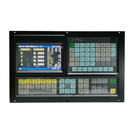
TOMATECH AUTOMATION Ⅰ Programming Ⅱ Operation Ⅱ Operation Ⅱ Operation CHAPTER 1 OPERATION MODE AND DISPLAY INTERFACE 1.1 Panel Division TAC-100XT,TAC-1002T-V CNC system uses an integrated panel, which is divided as follows:... -
Page 174: State Indication
TOMATECH AUTOMATION Ⅱ Operation 1.1.1 State indication Indicator for axis zero return completion Three-color light 1.1.2 Display Submenu Menu Remark To enter Position interface including RELATIVE POS, ABSOLUTE POS, POS & PRG, INTEGRATED POS page. “ABSOLUTE POS” page can display the current absolute coordinates, clear out machining count, machining time;... -
Page 175: Machine Panel
TOMATECH AUTOMATION Set/search G54~G59 coordinate system and zero offset value in workpiece coordinate system page; Set/search use information of current tool life Enter alarm interface including alarm information, alarm log page Search CNC alarm, CNC warning, PLC alarm, PLC warning in alarm information page;... - Page 176 TOMATECH AUTOMATION...
-
Page 177: Summary Of Operation
TOMATECH AUTOMATION Ⅱ Operation 1.2 Summary of Operation Mode There are 8 modes inTAC-1002T, which are Edit, Auto, MDI, Machine zero, Step/MPG, Manual,Program Zero, and MPG trial-cut modes. Edit mode In this mode, the operation of part program setup, deletion and alteration can be performed. -
Page 178: Display Interface
The chapter introduces page switch, relationship between operation input and soft key, and concrete operation methods. TAC-100XT has 9 function keys including POS, PRG, SET, etc. on its edit keyboard. Each function key corresponds to one interface which has many pages and operation soft keys, which are shown below: 1.3.1 POS interface... -
Page 179: Prg Interface
TOMATECH AUTOMATION is executed; CUT TIME: the system counts the time when the automatic run is started, time unit is hour,minute and second in order. The part counting and cut time are memorized at power-down, the clearing ways for them are shown below: Ⅱ... - Page 180 TOMATECH AUTOMATION Press to enter PRG interface, which includes. Press repetitively PRG keys to switch interfaces. Ⅱ O 1) PRG page In the page, the program content including current block can be displayed. Press the program content can be viewed forward or backward by pressing or key.
-
Page 181: Alarm Interface
TOMATECH AUTOMATION Note: The axis names of Y, the 4 , the 5 axis is defined by No.225. 2) MACRO interface There are 25 pages in this interface, which can be shown by pressing or key. In Macro window there are 600 (No.100~No.199 and No.500~No.999) macro variables which can be specified by macro command or set directly by keypad. -
Page 182: Parameter Interfaces
TOMATECH AUTOMATION Chapter 1 Operation Mode and Display Interface Ⅱ Operation 1) CNC setting page 2) System clock page 3) Document management page Ⅱ Operation 1.3.6 PARAMETER Interfaces Press to enters PARAMETER interface including pages , , , which can be switched by pressing repetitively or the corresponding soft keys. -
Page 183: Ladder Interface
TOMATECH AUTOMATION 1.3.9 Ladder Interface Press to enter LADDER interface including pages , , , which can be switched by pressing repetitively or corresponding soft keys. The interface is shown below: Chapter 1 Operation Mode and Display Interface Ⅱ Operation 1) PLC I/O state page The page can display PLC I/o state information. -
Page 184: Chapter 2 Power On/Off And Protection
TOMATECH AUTOMATION parameter, functional command and network in the current displayed block, and move the cursor to the corresponding position. (3)Press , to locate the cursor to the home or end of the current block. 3) PLC data page PLC data includes K, D, DT, DC, which can be set in the page. - Page 185 TOMATECH AUTOMATION overtravel of X, Y, or Z. 2.3.1 Hardware overtravel protection The stroke switches are fixed at the positive and negative maximum travel of the machine X, Z, Y axis respectively, they are connected by the following figure. And the BIT3 of bit parameter No.172...
- Page 186 TOMATECH AUTOMATION these incidents. This section mainly describes the resolutions that the system is capable of under the emergency situation. Please see the relative explanation on these resolutions under the emergency by machine manufacturer. 2.4.1 Reset Press key to resetTAC-1002T system when there are abnormal output and axis operations: 1 All axes motion stops;...
- Page 187 TOMATECH AUTOMATION Ⅱ Operation should be cut off immediately to avoid the accidents. But it should be noted that there may be a large error between the CNC coordinates displayed and the actual position. So the toolsetting operation should be performed again.
- Page 188 TOMATECH AUTOMATION press or and the 5th axis feeds negatively or positively, and its feeding stops if the key is released. The rapid override time-tuning is enabled. In Manual mode, press key to make the indicator OFF, and the rapid traverse is disabled and manual feed is executed.
- Page 189 TOMATECH AUTOMATION 3.2 Other Manual Operations 3.2.1 Spindle CCW, CW, stop control : In Manual mode, the spindle rotates counterclockwise if pressing this key; : In Manual mode, the spindle stops if pressing this key; : In Manual mode, the spindle rotates clockwise if pressing this key.
- Page 190 TOMATECH AUTOMATION And it is cancelled after a setting time by data parameter DT013; M32 is to execute lubricating output and the output is cancelled after a time set by DT013. If the setting time is not yet up, M33 is executed to cancel the lubricating output.
- Page 191 PLC parameter:K13.0 1/0:tailstock control valid/invalid PLC parameter: K13.1 1/0: the spindle rotation and the tailstock forward/backward are/not interlocked Note: The tailstock function is only for TOMATECH 980TDc-V CNC system. 3.2.7 Hydraulic control : press it to switch the hydraulic motor ON/OFF in any mode.
-
Page 192: Increment Selection
TOMATECH AUTOMATION Chapter 4 MPG/Step Operation Ⅱ Operation CHAPTER 4 MPG/STEP OPERATION In MPG/Step mode, the machine moves by a specified increment. 4.1 Step Feed Set the system parameter No.001 Bit3 to 0, and press key to enter the STEP working mode, it displays as follows: 4.1.1 Increment selection... -
Page 193: Moving Axis And Direction Selection
TOMATECH AUTOMATION are all active. For example, to press key, the window is shown as follows: 4.2.2 Moving axis and direction selection In MPG mode, press , , , , , key, the corresponding axis will be selected. For example, press key and the window is shown below: Volume Ⅱ... -
Page 194: Explanation Items
TOMATECH AUTOMATION In MPG/Step mode, if the spindle speed is controlled by analog voltage output, the spindle speed may be overrided. Pressing , can change the spindle speed in real-time to adjust 8 steps of 50%~120 % of the spindle override 4.2.4 Explanation items... -
Page 195: Block Execution
TOMATECH AUTOMATION 5.2 Block Execution After the word is input, is pressed and the display is as follows: After the code words are input and is pressed to display the block, key is pressed to execute the input block. During the execution, , and Emergency Stop button may be pressed to terminate these code words execution. -
Page 196: Program Creation
CNC to CNC, or CNC to PC can also be done. To prevent the program to be altered or deleted accidentally, a program switch is set up for this TAC-100XT system. And it must be turned on before program editing. Please see details in Section 10.1.1 of the part. -
Page 197: Searching A Character
TOMATECH AUTOMATION Ⅱ Operation 2) Press ,input orderly , , , in the pop-up dialog box(taking example of creating O0001, the leading zero can be omitted when it is input). It display is shown below: 3) Press ( or ) to create the new program. The current page is automatically switched into the program content page. -
Page 198: Inserting A Character
TOMATECH AUTOMATION the next window, if it windows to the end of the program, the cursor moves to the last row and 1st column of the program; 2. Finding: To search for the specified character upward or downward from the... -
Page 199: Deleting A Character
TOMATECH AUTOMATION automatically generated when inserting the code address; if the cursor is located at the row head, the space will not be generated, and it should be inserted manually. Note 2: In the Insert mode, if the previous bit before the cursor is a decimal point and the cursor is located at the row end, input an address word, the “0”... -
Page 200: Copying And Pasting A Block
TOMATECH AUTOMATION Ⅱ Operation 1) Press in Edit mode to enter program interface, and press to enter program content page. 2) Move the cursor to the head of the block to be deleted, then press key. 6.1.8 Copying and pasting a block Steps: 1) Select Edit mode, and the program content page is displayed;... -
Page 201: Creating And Modifying A Program Annotation
Note: The system cannot execute the program search and the scan in macro program edit state. 6.1.12 Creating and modifying a program annotation TAC-100XT can add annotation to each line, and its steps are shown below: 1) Select Edit mode, press to enter program interface, press to enter the program content page;... -
Page 202: Deleting All Programs
TOMATECH AUTOMATION 6.2.2 Deleting all programs Steps: 1) Refer to Section 6.2.1, Method 2 to enter the local program page; 2) Press to enter the next menu and the display is shown below: Ⅱ Operation 3) Press , and then press ,the all program are deleted. -
Page 203: Executing A Program
TOMATECH AUTOMATION 3) Pressing can enter the subordinate menu, which can be omitted. The display is shown below: 4) Press , to move the cursor to the program name which is to be selected. 5) Refer to the above Step 3) to enter the subordinate menu, at the moment, press directly to open it. -
Page 204: Program Management
TOMATECH AUTOMATION 2) Press to input a new program name; 3) Press . Chapter 6 Program Edit and Management Ⅱ Operation Method 2: 1) Select Edit mode, press to enter the program interface, and in necessity press to enter the local directory page:... -
Page 205: Tool Positioning Setting
TOMATECH AUTOMATION Area 4 Area 2 Area 3 Chapter 6 Program Edit and Management Ⅱ Operation 4) The operation mode is switched by pressing any of the keys among , , , , or ; 5) The data transmission 6) Refer to II OPERATION, Chapter 12 7) Cooling control Refer to II Operation, Section 3.2.3... -
Page 206: Trial Toolsetting
TOMATECH AUTOMATION 3. Select a tool by random (usually the 1 tool, this tool will be used as the reference tool); 4. Position the tool nose of the reference tool to a point (toolsetting point), as shown in Fig. 5. In PRG STATE page of the MDI mode, set up the workpiece coordinate system by the command G50 X__ Z__;... -
Page 207: Toolsetting By Machine Zero Return
TOMATECH AUTOMATION press , and the CNC records the absolute values of the position, at the moment, directly move the tool; 7) Measure the diameter "α" (supposing α=15) ; 8) Press key to enter the Offset interface, select the TOOL OFFSET window, then move the cursor by pressing , key to select the corresponding offset number;... - Page 208 TOMATECH AUTOMATION only needs to be set again, and a machine zero return should be done before the toolsetting. The machining could be continued by performing a machine zero return at power on after power-off, which is very convenient for the operation.
- Page 209 TOMATECH AUTOMATION β 1 Surface B1 Surface A1 Ⅱ Operation 14) Make the tool to cut on Surface A1; 15) Retract the tool along X axis without Z axis moving and stop the spindle; measure the distance "β1" between the Surface A1 and the workpiece coordinate system origin (supposing β1=1) ;...
-
Page 210: Coordinates Record
TOMATECH AUTOMATION workpiece Chapter 7 Tool Offset and Setting Ⅱ Operation coordinate system is (a,b), the setting value of system parameter No.047 should be close to a,b. 7.4 Coordinates Record When the trail-cut toolsetting or machine zero return toolsetting is executed, the coordinates record function can be used to get the convenient toolsetting operation. -
Page 211: Offset Setting
TOMATECH AUTOMATION 7.5.1 Offset setting 1) Press key to enter the offset setting page, select the desired window by pressing the 2) Move the cursor to the location of the tool offset, wear number to be input. Scanning: Press , to move the cursor in sequent... -
Page 212: Clearing The Offset Values
TOMATECH AUTOMATION No. X Z T R 00 0 0 0 0 01 16.380 -24.562 0 0 In machining, the actual external diameter measured of workpiece is Ф55.561, so the offset value of No.01 can be altered as follows table: No. -
Page 213: Locking And Unlocking The Offset Value
TOMATECH AUTOMATION Ⅱ Operation 7.5.6 Locking and unlocking the offset value In order to protect the offset value to be operated by mistaken, the offset values can be put into lock, the operation steps are as follows: 1) Move the cursor to the location of the offset number to be locked;... -
Page 214: Stop Of Automatic Run
TOMATECH AUTOMATION , make a check whether the cursor is located at the block to be executed. 8.1.3 Stop of automatic run Stop by code (M00) 1. M00 After the block containing M00 is executed, the auto run is stopped. So the modal function state are all reserved. -
Page 215: Automatic Run From An Arbitrary Block
TOMATECH AUTOMATION mode, the current block “dwells” immediately; when the Auto mode is switched to the Edit, MDI mode in Auto mode, the “dwell” is not displayed till the current block is executed. Note 1: Ensure that the fault has been resolved before cancelling the emergency alarm. -
Page 216: Spindle Speed Adjustment
TOMATECH AUTOMATION Note 2: When the rapid override is F0, the min. rapid traverse rate is set by bit parameter No.032. 8.1.6 Spindle speed adjustment While the spindle speed is controlled by the analog voltage output in Auto mode, it can be adjusted by spindle override. -
Page 217: Machine Lock
TOMATECH AUTOMATION Rapid traverse switch ON Rapid traverse Max. manual feedrate Rapid traverse switch OFF Manual feedrate or rapid traverse(see note) Manual feedrate Note 1: The rate by manual feedrate or rapid rate is set by the BIT6 of the CNC system parameter No.004. -
Page 218: Mpg Trial-Cut
TOMATECH AUTOMATION mode. 8.3 MPG Trial-cut The user can use MPG trial-cut function after editing part programs, check the run path of program. In MPG trial-cut function, rotating MPG controls the execution speed of program, which can easily check the program error conveniently. -
Page 219: Notes In Mpg Trial-Cut Mode
TOMATECH AUTOMATION [MPG pulse amount per 1 second]×λ×([No.241 setting value]/100)×(8/1000) At the moment, when the speed by rapidly rotating MPG exceeds the clamped, the rapid traverse speed is clamped at the setting value by parameter, i.e.: [MPG pulse amount per 1 second]×λ×([No.241 setting value]/100)×(8/1000) ≤1 8.3.3 Notes in MPG trial-cut mode... -
Page 220: Other Operations
TOMATECH AUTOMATION Chapter 8 AUTO Operation Ⅱ Operation the next block is valid again. The related G commands include: G31, G36, G37 8.4 Other Operations 1. In Auto mode, press key to switch on/off the cooling; 2. Press any of the , , , , , , keys to switch the operation modes;... -
Page 221: Machine Zero Return
TOMATECH AUTOMATION chapter is based on theTAC-1002T standard PLC program! Chapter 9 Zero Return Operation Ⅱ Operation Note 1: The tool offset is not changed for the program zero return operation, if there is offset, the return position is the point set by G50. -
Page 222: Other Operations In Zero Return
TOMATECH AUTOMATION 9.3 Other Operations in Zero Return 1) The spindle rotates (CW, CCW), stops. 2) The cooling is ON or OFF. 3) The lubricating control. 4) Manual relative tool change. 5) The spindle override tuning. 6) Rapid override tuning. - Page 223 TOMATECH AUTOMATION level setting function, and its password grade is divided into five, from high to low grade: grade (machine manufacturer), 3 grade (device management), 4 grade (engineer), 5 grade (machining Ⅱ Operation grade(operation limit). The current operation grade is displayed in “Current operation), 6 Level:_”...
-
Page 224: Parameter Operation
TOMATECH AUTOMATION grade 3 digits 123 grade None None Note 2: When the operation level is less than or equal to the 3 grade ( 3 or 6 grade) and system is turned on again, the operation level does not change. When the level is the 2... -
Page 225: Clock Setting
TOMATECH AUTOMATION recovered (read). Programs can be stored in the CNC when the backup or recovery is executed. The display is shown below: 1) Option explanation: Backup current parameters (user): the user to backup the CNC data (store) Resume backup parameters(user): the user resumes the backup data (read) -
Page 226: Graphic Display
TOMATECH AUTOMATION 10.3 Graphic Display Press key to enter the path page as follows: Press to open the next page menu as follows: 1) The START, STOP and CLEAR of the graphic path In the path display page, press the (or ) and the system starts the drawing;... -
Page 227: Parameter Setting
TOMATECH AUTOMATION Chapter 10 Data Setting, Backup and Restore Ⅱ Operation Bit parameter No.175 Bit1 Bit0 Graphic path coordinate display 10.4 Parameter Setting Parameter setting can adjust related characteristics of the drive unit and machine. Press to enter Parameter interface which includes , , , as follows: 10.4.1 State parameter... -
Page 228: Data Parameter, Pitch Compensation
TOMATECH AUTOMATION c) Move the cursor to the parameter number to be set(the method is referred to Section 10.4.1 Step c); d) Press to enter the bit alteration mode, at the moment, some bit of the parameter is backlighted. Press or to move the cursor to the bit to be altered, then key in 0 or e) After all parameters setting is finished, the PARM SWT needs to be set to OFF for security. -
Page 229: Chapter 11 U Operation Function
Ⅱ Operation CHAPTER 11 U OPERATION FUNCTION 11.1 File Management Function Introduction TAC-100XT has the file management function to execute the file copy, data backup, data resume, the system upgrading (2 grade) and so on. In any states, press to select the setting interface, press to enter the file management page. -
Page 230: Often Used File Operation Function Introduction
TOMATECH AUTOMATION press , to move the line where the current cursor is. 11.2 Often Used File Operation Function Introduction 11.2.1 File extension and return 1) Move the cursor to the required extension file, press to extend it as follows:... -
Page 231: Data Copy And Resume
TOMATECH AUTOMATION window, is pressed and the file in the CNC is copied to the U disk. 11.3 Data Copy and Resume In the file managemetn page, backup, resume the CNC data (including the system parameters, part parameter, tool compensation, pitch compensation, ladder parameters, ladder, alarm log and so on) via the U disk. -
Page 232: Format Of Data Backup/Resume File
TOMATECH AUTOMATION “U:\TAC-1002T_backup\serial Ⅱ Operation number” remains unchanged. For the above reason, the user should execute the operation path selection during resuming data: Default path :U:\TAC-1002T_backup\user Serial number path:U:\TAC-1002T_backup\serial number Example: backup/resume data of many CNC systems When the user backups the system A (serial number CT0000001), the generated file by data backup is “U:\TAC-100XT_backup\CT0000001”... - Page 233 TOMATECH AUTOMATION requirements .ld2 PLC programs PLC parameter plcpar .dat K, D, DT, DC parameters Part program O0000~O9999 .CNC Part programs 11.3.5 Level explanation of data backup/resume operation System parameters More than the 5 grade password Tool compensation data More than 5...
-
Page 234: Notes
TOMATECH AUTOMATION password Resume operation Part programs More than 4 grade(including the 4 grade) password 11.4 Notes The user should pay more attention to the followings during executing the data backup/resume operation: 1) Need more than the 2 grade password(including the 2 grade) to resume more than (including be equal to) 9000 part programs;... -
Page 235: Receiving Files (Cnc→Pc)
TOMATECH AUTOMATION TOMATECHComm software takes an administrator as a unit to complete management. When it run firstly, it does not upload project files, at the moment, the user should create an project program or upload project to execute the communication operation. The display is shown below after... -
Page 236: Part Program Management
TOMATECH AUTOMATION Ⅱ Operation Hereby, the user can select the required receiving files from CNC including part programs, tool compensation (TOFF.CMP), pitch compensation (WOFF.WMP), parameters (PARA.PAR). The part programs which can be altered are saved to the file name of the CNC. Move the cursor to... -
Page 237: Communication Setting Baud Rate
TOMATECH AUTOMATION cable when PC and CNC are turned off. 12.2.2 Communication setting baud rate Setting the baud rate of communication ensures that the baud rate of PC is the same that of the CNC communication. The communication baud of the serial port is set by No.044; click [Communication Setup]... -
Page 238: Programming
TOMATECH AUTOMATION Tool number Tool shape Explanation No. 4 Threading tool, tool nose angle 60° 13.1 Programming Set up the workpiece coordinate system as Fig.13-1 according to the machining process and the codes introduced in this manual. The programming steps are as follows: O0001;... -
Page 239: Program Input
TOMATECH AUTOMATION N0200 T0303; Change for the No.3 tool and execute its offset N0210 G0 Z-56 X42; Approach to the part N0220 G1 X30 F100; Cut the Φ30 groove N0230 G1 X37 F300; Return N0240 G1 X40 W1.5; Chamfering N0250 G0 X42 W30; Keep the width of the grooving N0260... -
Page 240: Creating A New Program
TOMATECH AUTOMATION 13.2.2 Creating a new program Enter the local catalog page in Edit mode, press address key , choose a name that is not same with the ones in this window (i.e. 0001), key in the number key , , , and to create a new program as follows: Ⅱ... -
Page 241: Connection
TOMATECH AUTOMATION Ⅱ Operation 6) Release the tool along Z when X does not move, and stop the spindle, measure the dimensions of the outer circle of the part (e.g. The measuring value is 135mm); 7) Execute G50 X135 command in PROGRAM>MDI page in MDI mode to set the coordinate of X axis;... -
Page 242: Chapter 1 Nstallation Layout
TOMATECH AUTOMATION CHAPTER 1 NSTALLATION LAYOUT 1.1 GK980TDc System Connection 1.1.1 GK980TDc,TAC-1002T-V rear cover interface layout AXIS 5 SPINDLE INPUT CN61 +12V CN11 AXIS X OUTPUT CN62 CN15 CN13 CN12 AXIS Z AXIS Y COM PORT CN51 POWER SUPPLY CN31... -
Page 243: Interface Explanation
Fig.1-2 TOMATECH 980TDc-V rear cover interface layout Ⅲ Connection 1.1.2 Interface explanation Power box: TOMATECH-PB2, for +5V, +24V, +12V, -12V, GND power supply Filter(optional): Input terminals for 220V AC power, PE terminal for grounding, output terminals to L, N terminals of TOMATECH-PB2 power box CN1: power supply interface CN11: X axis,pin15 D female, connect with X drive unit... -
Page 244: Preconditions Of The Cabinet Installation
TOMATECH AUTOMATION See Appendix Ⅰ, Ⅱ. 1.2.2 Preconditions of the cabinet installation The dust, cooling liquid and organic resolution should be effectively prevented from entering the cabinet; The designed distance between the CNC back cover and the cabinet should be not less... -
Page 245: Chapter 2 Definition & Connection Of Interface
TOMATECH AUTOMATION current, the wiring should follow the following: Table 1-1 The Wiring requirement Group Cable type Wiring requirement AC power cable A AC coil AC contactor Tie up A group cables with a clearance at least 10cm from that of B, C groups, or shield A group cables from... -
Page 246: Drive Unit Alarm Signal Nalm
TOMATECH AUTOMATION externally, and the interior circuit for them is shown in Fig. 2-2: Fig. 2-2 Interior circuit of code pulse and direction signals 2.1.3 Drive unit alarm signal nALM The low or high level of the drive unit alarm is set by the CNC parameter No.009 Bit0, Bit1, Bit2, Bit3 and Bit4, its interior circuit is shown in Fig. -
Page 247: Axis Enable Signal Nen
TOMATECH AUTOMATION nCP– nDIR Chapter 2 Definition and Connection of Interface Signal Ⅲ Connection Type 1: Type 2: Fig. 2-4 Signal types by drive unit 2.1.4 Axis enable signal nEN nEN signal output is active as CNC works normally (nEN signal to 0V on); when the drive unit alarm or emergency alarm occurs, CNC cuts off nEN signal output (nEN signal to 0V off). -
Page 248: Connection To A Drive Unit
+24V Chapter 2 Definition and Connection of Interface Signal Ⅲ Connection 2.1.7 Connection to a drive unit TOMATECH 980TDc/TAC-100XT-V is connected with our drive unit, shown in Fig. 2-11: 980TDc side (CN11,CN12, CN13, CN1 4) GS2000T-N side CN1 nCP+ 1 2 PULS+... - Page 249 TOMATECH AUTOMATION TAC-100XT(CN11, CN12,CN13,CN14) Connection betweenTAC-1002T and DA98 (A) DA98(A)signal interface Metal shell DA98B signal interface PULS+ SIGN+ PULSALM 38 COM+ 32 DG 14 SIGNnCPnCP+ nDIR+ nALM 10 nDIRConnection betweenTAC-1002T and DA98B TAC-100XT(CN11, CN12,CN13,CN14) Metal shell Metal shell Ⅲ Connection...
-
Page 250: Being Connected With Spindle Encoder
90° and their maximum signal frequency is less than 1MHz; the encoder pulses TAC-100XT are set at will by parameter, the setting range is from 100 to 5000. Its interior circuit is shown in Fig. 2-13: (n=A, B, C) Fig. -
Page 251: Being Connected With Mpg (Manual Pulse Generator)
TOMATECH AUTOMATION *PCS/PCS Encoder C phase pulse Chapter 2 Definition and Connection of Interface Signal Ⅲ Connection Fig. 2-14TAC-1002T/TAC-100XT-V is connected with the encoder 2.3 Being Connected with MPG (Manual Pulse Generator) 2.3.1 MPG interface definition Fig. 2-15 CN31 MPG interface... -
Page 252: Spindle Interface
TOMATECH AUTOMATION TLP181 XHB+ XHA+ Fig. 2-16 MPG signal circuit TAC-100XT/TAC-100XT-V is connected with MPG shown in Fig. 2-17: Ⅲ Connection 3 HB+ HAHB- Metal shell TAC-100XT(CN31) MPG Null HBHANull 3 HB+ Metal shell TAC-100XT(CN31) Fig. 2-17TAC-1002T/TAC-100XT-V is connected with MPG 2.4 Spindle Interface... - Page 253 TOMATECH AUTOMATION Note 1: It is valid when PC5 is connected with 0V, and it is different with other feed axes(it is valid when PC of CN11~CN14 axis interface is connected with +24V). Note 2: They are valid when X5.0~X5.3 are connected with 0V, and they are different with other input signals( other are valid when they are connected with +24V).
-
Page 254: Connection To Inverter
Fig. 2-23ATAC-1002T is connected with PC Signal Explanation RXD Receiving data TXD Transmitting data GND Signal grounding 2: RXD 3: TXD 5: GND Ⅲ Connection 2.6 Power Interface Connection TOMATECH-PB2 power box is applied inTAC-1002T system, which involves 4 groups of... -
Page 255: I/O Interface Definition
+5V(3A) ,+12V(1A) ,-12V(0.5A) ,+24V(0.5A) , and its common terminal is COM(0V) . The connection of TOMATECH-PB2 power box toTAC-1002T XS2 interface has been done for its delivery from factory, and the user only need to connect it to a 220V AC power in using. - Page 256 TOMATECH AUTOMATION X0.4 DITW Tailstock for/backward X0.5 Emergency stop buttom X0.6 LIMU Overtravel release signal X0.7 Tool signal T05 X1.0 Tool signal T06 X1.1 Tool signal T07 X1.2 Tool signal T08 X1.3 DECZ Z axis homing decelerate signal X1.4 External cycle start signal X1.5...
-
Page 257: Input Signal
TOMATECH AUTOMATION X3.7 LMI5 axis overtravel input tion Fig.2-25 input Ⅲ Connection Fig.2-26 output interface (CN62) 2.7.1 Input signal Input signal means the signal from machine to CNC, when this signal is through on with +24V, the input is active; when it is off with +24V, the input is inactive. The contact of input signal... - Page 258 TOMATECH AUTOMATION Y 1.0 S1/M41 Spindle mechanical gear output 1 Y 1.1 S2/M42 Spindle mechanical gear output 2 Y 1.2 S3/M43 Spindle mechanical gear output 3 Y 1.3 S4/M44 Spindle mechanical gear output 4 Y 1.4 DOQPJ Chuck clamp output Y 1.5...
-
Page 259: I/O Function And Connection
TOMATECH AUTOMATION To drive LED A serial resistance is needed to limit the current (usually 10mA) that goes through the LED using ULN2803 output to drive LED, which is shown in Fig. 2-30: Fig. 2-30 To drive filament indicator An external preheat resistance is needed to decrease the current impact at power on by... - Page 260 Signal connection The ESP signal circuit is shown in Fig.2-33: Note! The I/O function significance of thisTAC-1002T /TAC-100XT-V turning machine CNC system is defined by PLC programs (ladders), and they are defined by the machine builder when matching with a machine, please refer to the manual the machine builder.
-
Page 261: Tool Change Control
TOMATECH AUTOMATION 2-34B: Fig. 2-34B Separate connection between the emergency stop and travel switch Control logic (1) Series connection between the emergency stop and travel switch When the contact of the emergency stop switch is cut off, the ESP signal is off to +24V, and CNC makes an emergency alarm. - Page 262 TOMATECH AUTOMATION Tool signal7/pre-graduation proximity switch (Yantai AK31) Also as OV3 input T08 CN61.11 X1.2 Tool signal8/tool post worktable overheat check(Yantai AK31) Also as OV4 input Input signal TCP CN61.35 X2.6 Tool post locking signal TL+ CN62.15 Y1.6 Tool post rotation(CW) signal TL- CN62.16 Y1.7 Tool post rotation(CCW) signal...
- Page 263 TOMATECH AUTOMATION =1 : check tool signal after the tool change is completed CHOT=0 : do not check tool post overheat =1 : check tool post worktable overheat D T 0 4 TLMAXT The maximum time limit for tool change...
- Page 264 TOMATECH AUTOMATION turns off TL- signal after a delay time specified by the data parameter No.085. So the tool change is over. ②When CHET(K0011.5) is set to 1(check tool signal after the tool change ends) and the tool post (CCW) rotation time ends to confirm whether the current tool input signal is consistent with the current tool No., if not, the system alarms.
- Page 265 TOMATECH AUTOMATION ③ The tool change process ends. ④ After the system outputs the too rotation(CCW) signal, when it has not received TCP signal in the time set by DT08, it alarms and closes TCP signal. ⑤ If the tool post has no locking signal, CTCP(K0011.3)is set to 0,at the time, the system does not check the tool post locking signal.
- Page 266 TOMATECH AUTOMATION the motor brake is turned on. ⑺.When the system delays 200ms,it closes the pregraduation electromagnetic output signal, and then the electromagnet is turned off. ⑻.The system checks the current tool no. again and confirms whether the encoding signal...
-
Page 267: Machine Zero Return
TOMATECH AUTOMATION C ● ● ● ● ● ● D ● ● ● ● ● ● E ● ● ● ● ● ● ● ● ● ● ● ● 4.2 Signal specification Sensor A, B, C, D: only check the tool, and are not any start signals Sensor E: it executes the inductive once when one tool change is executed, which makes tool pot stop and the start signal be locked. - Page 268 TOMATECH AUTOMATION PC4: 4th zero signal; PC5: 5th zero signal; Diagnosis data 0 0 0 DEC5 DEC4 DECZ DECY DECX Interface pin CN61.34 CN61.33 CN61.12 CN61.32 CN61.4 0 0 8 PC5 PC4 PCY PCZ PCX Interface pin CN15.10 CN14.3 CN13.3 CN12.3 CN11.3...
- Page 269 TOMATECH AUTOMATION deceleration signal and zero-point signal at the same time). Bit 2 1: During machine zero return, the deceleration signal of the Y axis (DECY) and one-rotation signal (PCY) are connected in parallel (use a proximity switch as a deceleration signal and zero-point signal at the same time).
- Page 270 TOMATECH AUTOMATION needed to be detected during machine zero return; 0: Machine zero point is not set on the 5 , Y, Z, X axes; deceleration signal and zero point signal are not detected during machine zero return; 1 8 3 MZR5 MZR4 MZRY MZRZ MZRX Bit4/Bit3/Bit2/Bit1/Bit0 1: The direction of machine zero return is negative;...
- Page 271 TOMATECH AUTOMATION again. And CNC begins to detect the encoder one-turn signal (PC), if this signal level skips, the motion will be halted. And the corresponding zero return indicator on the operator panel lights up for machine zero return completion.
- Page 272 TOMATECH AUTOMATION indicator on the operation panel lights up for zero return completion. Machine zero return by a proximity switch taken as both deceleration and zero signals ① Its sketch map is as follows: Sketch map of zero tongue for machine zero return mode B: Fig.
-
Page 273: Spindle Control
TOMATECH AUTOMATION Zero return speed Velocity ( High return speed Low return speed Return finish Time( Decelerates to stop Reversely Fig. 2-44-b C type machine zero return process A: Select the Machine Zero mode, press manual positive or negative (zero return direction by bit parameter No.183) feed key, the corresponding axis will move to the zero at a high... - Page 274 TOMATECH AUTOMATION SCLP CN62.7 Y0.6 Spindle clamped SPZD CN62.8 Y0.7 Spindle brake SVF CN62.37 Y3.0 Spindle servo OFF Output signal SFR CN15.22 Y5.2 Spindle rotation(CW) Its function is consistent with that of M03 Chapter 2 Definition and Connection of Interface Signal Ⅲ...
- Page 275 TOMATECH AUTOMATION 1 7 5 SAR Bit6 1: The spindle SAR signal is checked before cutting; 0: The spindle SAR signal is not checked before cutting. Data parameter 0 7 2 SAR_DELEY Delay check time (ms) of the spindle speed arrival.
- Page 276 TOMATECH AUTOMATION Brake Stop Stop signal 机 床 侧 ine side +5V CNC +24V Chapter 2 Definition and Connection of Interface Signal Ⅲ Connection ② When M03(M04)output is valid, M04(M03)is executed, the alarm occurs. ③ When №175.6 is set to 1, the system checks whether the speed arrival signal SAR is valid, if it is valid, the system normally runs, if not, “Check speed arrival……”...
-
Page 277: Spindle Switching Volume Control
TOMATECH AUTOMATION abnormality alarm. Note 1: In the emergency stop, it turns off M03, M04, M08 signals, and outputs M05 signal; Note 2: Whether M03, M04 is cancelled is set by BIT3 of the bit parameter No.009 when CNC is reset. - Page 278 TOMATECH AUTOMATION Fig. 2-47 Control parameter Bit parameter 0 0 1 ACS Bit4 =1: Spindle analog volume control, set to 1 if using spindle automatic gearing =0: Spindle switching volume control K 1 5 SHT AGIM AGIN AGER AGER =1: Spindle automatic gearing active...
-
Page 279: Spindle Eight-Point Orientation Function
TOMATECH AUTOMATION When spindle auto gearing is used to control automatic spindle mechanical gear switching, CNC executes S□□□□ code, it calculates the analog voltage output to spindle servo or frequency inverter based on the parameter of the current gear by M4n (M41~M44 to data parameters No.037~No.040 respectively) to make the actual speed to be consistent with the S code. - Page 280 TOMATECH AUTOMATION Spindle abnormality alarm signal It is valid when 0V is input STAO CN62.41 Y3.4 Spindle orientation start signal SP0 CN62.42 Y3.5 Orientation position 0 SP1 CN62.43 Y3.6 Orientation position 1 SP2 CN62.44 Y3.7 Orientation position 2 SFR CN15.22 Y5.2 Spindle rotation (CW)
- Page 281 TOMATECH AUTOMATION 4-point orientation. Control parameter K 1 5 SPOR SPOR =1: The spindle eight-orientation function is valid. =0: The spindle eight-orientation function is invalid. K 1 7 SALM SALM =1: The system alarms when the spindle abnormality check input signal is LOW(it is not connected with 0V).
- Page 282 TOMATECH AUTOMATION external speed control mode. Orientation sequence drawing Orientation function wiring diagram betweenTAC-1002T and DAP03 TAC-100XT signal interface DAP03 signal interface Ⅲ Connection CN15 22 ALM5 7 COMCOM+ 24 SON SVC-GND 14 VCMD+ 9 SFR 15 VCMD- 16 PAO+...
-
Page 283: Spindle Cs Axis Control Function
23,35 3,16 11,17 Orientation function wiring diagram betweenTAC-1002T and GS3000Y-N TAC-100XT signal interface GS3000Y-N signal interface Note 1: When the system is matched with GS3000Y-N, the single-point orientation is defaulted; up to 4 points orientation can be realized. Note 2: GS3000 Series signal interface CN1 adopts DB44 3-stripe male plug. - Page 284 TOMATECH AUTOMATION the rigid tapping) SFR CN15.22 Y5.2 Spindle rotation CW Output signal SRV CN15.23 Y5.3 Spindle rotation CCW Command format M14: The spindle is switched from the speed control mode into the position M15: The spindle is switched from the position control mode into the speed...
- Page 285 TOMATECH AUTOMATION switch signal; 2) Drive unit starts the switch control mode. After the switch is completed, Drive→PLC outputs the speed/position switch state signal VPO; 3) After the PLC receives the spindle speed/position switch state signal VPO, the spindle contour control switch signal CON is set to 1.
- Page 286 TOMATECH AUTOMATION ZOUT- 15 DIR5- ALM5 DIR5 CP5+ CP5- 34 SIGNZOUT+ PULSSIGN+ PULS+ COMCOM+ SVC-GND 14 VCMD+ 9 SFR 12 VP 44 VPO 15 VCMD- 16 PAO+...
-
Page 287: Multiple Spindle Function
Wiring diagram betweenTAC-1002T and GS3000Y-N spindle servo unit (the 5 axis is Cs axis in the following example) TAC-100XT signal interface GS3000Y-N signal interface TAC-100XT signal interface DAP03 signal interface Ⅲ Connection Note 1: CN15 signal interface onTAC-1002T side adopts DB25 2-stripe male plug, CN21 adopts DB15 2-stripe female plug. - Page 288 TOMATECH AUTOMATION in-position signal Output signal VP2 CN62.36 Y2.7 The 2 spindle speed/ position control switch output Chapter 2 Definition and Connection of Interface Signal Ⅲ Connection TAP2 CN62.39 Y3.2 The 2 gain selection signal of the 2 spindle speed loop (used to rigid tapping) M63 CN62.40 Y3.3 The 2...
- Page 289 TOMATECH AUTOMATION rotary axis (A-type); 11: set the additional axis to the rotary axis (B-type); 10: set the additional to be invalid. 1 9 6 MSI CSS MSEN Bit7 1: The multiple spindle control B type; 0: The multiple spindle control A type.
- Page 290 TOMATECH AUTOMATION of the spindle on the panel still controls the 1 spindle. 1.5. The spindle override of the 2 spindle is fixed to 100%. 1.6. Cs axis control of two spindles can be separately switched and the current used...
- Page 291 TOMATECH AUTOMATION does not check the chuck in-position signal. Connection diagram between the 2 spindle and DAP03 CN14 VPO2 TAP2 ZOUT+ 10 DIR- 4 +24V CP34 SIGNZOUT- PULSSIGN+ PULS+ COM+ 24 SON SVC-OUT2 SVC-GND 14 VCMD+ 9 SFR...
-
Page 292: Rigid Tapping Function
23/35 37/38 Connection diagram between the 2 spindle and GS3000Y-N spindle servo unit TAC-100XT signal interface GS3000Y-N signal interface TAC-100XT signal interface DAP03 signal interface Ⅲ Connection Note: CN1 on GS3000Y-N Series adopts DB44 3-stripe male plug; 2.8.10 Rigid tapping function... -
Page 293: External Cycle Start And Feed Hold
TOMATECH AUTOMATION mode. After the rigid tapping return, the tapping spindle returns to the previous control mode. ④ When the system is in the rigid tapping state, the manual movement tapping spindle cannot be performed. ⑤ The rigid tapping state is cancelled in reset or emergency stop. -
Page 294: Cooling Control
TOMATECH AUTOMATION TAC-100XT +24V Normal-close contact without lock Ⅲ Connection 2.8.12 Cooling control Relevant signal (defined by standard PLC program) Type Sign Interface Address Function Remark Output signal M08 CN62.1 Y0.0 Cooling control output M08 Cooing ON Command format M09 Cooling OFF Signal connection Its internal circuit is shown in Fig. - Page 295 TOMATECH AUTOMATION RSJG =1: when is pressed, CNC does not close M03, M04, M08, M32 output signal. =0: when is pressed, CNC closes M03, M04, M08, M32 output signal. K 1 6 M32A M32A =1: output lubricating in starting the system when the automatic lubricating is valid...
-
Page 296: Chuck Control
TOMATECH AUTOMATION 2.8.14 Chuck control Relevant signal (defined by standard PLC program) DIQP: Chuck control input signal DOQPJ: Inner chuck clamping output/outer chuck releasing output signal DOQPS: Inner chuck releasing output/outer chuck clamping output signal NQPJ: Inner chuck clamping in-position/outer chuck releasing in-position signal, sharing a... - Page 297 TOMATECH AUTOMATION =0: Chuck clamping and releasing signals are level output Signal connection The circuit of DOQPJ/DOQPS is shown in Fig. 2-52: Fig. 2-52 Sequence ①When SLQP=1, SLSP=0, NYQP=0, CCHU=1, CNC chooses inner chuck mode, and chuck in-position signal detecting is active: DOQPS: chuck releasing output;...
-
Page 298: Tailstock Control
TOMATECH AUTOMATION active. ③The interlock between the chuck and the spindle When SLQP=1, SLSP=0, M3 or M4 is active, the alarm is issued if M13 is executed and output is unchanged. When SLQP=1, SLSP=0, CCHU=1, if M12 is executed in MDI or Auto mode, CNC does execute next code till it detects the chuck clamping in-position signal is active. -
Page 299: Low Pressure Detection
TOMATECH AUTOMATION Sequence (defined by standard PLC program) The sequence of tailstock is shown in Fig. 2-56: Tailstock advancing (DOTWJ) and retracting(DOTWS) are both inactive when power on; when the tailstock input (DITW) is active for the 1 time, tailstock advancing is active; when it is... -
Page 300: Hydraulic Control (Only Applied To 980Tdc-V)
TOMATECH AUTOMATION alarm by CNC; ②When PB3=1 and SPB3=1, PRES is connected to 0V, which is confirmed to be low pressure alarm by CNC; ③When low pressure alarm detection function is selected, once CNC detects the low pressure alarm signal PRES to be active, and the signal holding time is over the setting by the data parameter No.069 alarm is issued by CNC. -
Page 301: Cnc Macro Variables
TOMATECH AUTOMATION Control parameter PLC status parameters K 1 4 SGSP SPB4 PB4 PB4 =0: Protection door detection function is invalid; =1: Protection door detection function is valid; SPB4 =0: When SAGT is at low level (disconnect with +24V), the protection door is closed;... -
Page 302: External Override
TOMATECH AUTOMATION 2.8.20 External override Related signals Type Sign Interface Address Function Remark OV1 CN61.8 X0.7 External override 1 OV2 CN61.9 X1.0 External override 2 OV3 CN61.10 X1.1 External override 3 Input signal OV4 CN61.11 X1.2 External override 4 The external... - Page 303 TOMATECH AUTOMATION ZSSY2080 MPG Chapter 2 Definition and Connection of Interface Signal Ⅲ Connection 9 X6.3 EMP0 Increment ×1 22 X6.4 EMP1 Increment ×10 23 X6.5 EMP2 Increment ×100 11, 12, 13 GND 14,15 +5V 17,18 +24V Related parameters State parameter 0 0 1 MPG Bit3 =0: Step working mode.
- Page 304 TOMATECH AUTOMATION Signal type Sign Signal interface Address Function CLPY CN62.31 Y2.2 Yellow— normal state (non-running, non-alarm state) CLPG CN62.32 Y2.3 Green—running state Output signal CLPR CN62.33 Y2.4 Red—alarm state 2.8.23 Extended M Function Relevant signals(standard PLC program) Ⅲ Connection Signal interface Address Address characters Function CN62.36 Y2.7 EMOT1 Extended M function signal 1...
- Page 305 TOMATECH AUTOMATION Address Address characters Function CN62.03 Y0.2 HOLD HOLD release output Control parameter PLC state parameter K 1 8 HOLD HOLD =0:HOLD release control is invalid. =1:HOLD release control is valid. Function Chapter 2 Definition and Connection of Interface Signal Ⅲ...
- Page 306 1.5S, and the system executes them like the above cycle. 2.9 Commonly Use Sign of Electricity Drawing TAC-100XT DC24V power supply and the electromagnetic valve with power working current separately use DC24V, and the electronic component explanations are as follows:...
-
Page 307: Parameter Description (By Sequence)
TOMATECH AUTOMATION Volume Ⅲ Connection CHAPTER 3 PARAMETERS The CNC bit and data parameters are described in this chapter, various functions can be set by these parameters. The major parameter data type are listed as follows: Data type Range (1) Bit... - Page 308 TOMATECH AUTOMATION Volume Ⅲ Connection 0: Conceal clock Bit4 1: Tool life management group skip active 0: Tool life management group skip inactive Bit3 1: Tool life management active in MDI mode 0: Tool life management inactive in MDI mode...
- Page 309 TOMATECH AUTOMATION Volume Ⅲ Connection 0: Axial output wave is square; 0 0 6 *** *** *** ZM5 ZM4 ZMY ZMZ ZMX Bit4 1: 5 zero return mode C 0: 5 zero return mode B Bit3 1: 4 zero return mode C...
- Page 310 TOMATECH AUTOMATION Bit4 1: Direction signal (DIR) in 5 positive movement is HIGH 0: Direction signal (DIR) in 5 negative movement is HIGH Bit3 1: Direction signal (DIR) in 4 positive movement is HIGH 0: Direction signal (DIR) in 4...
- Page 311 TOMATECH AUTOMATION 0 1 1 1 0 15 0 1 1 1 1 16 1 0 0 0 0 17 1 0 0 0 1 18 1 0 0 1 0 19 1 0 0 1 1 20 1 0 1 0 0 21...
- Page 312 TOMATECH AUTOMATION Bit1 1: Program end sign EOB displayed for “;” 0: Program end sign EOB displayed for “*” Bit0 1: Prior to machine zero return after power on, manual rapid traverse active 0: Prior to machine zero return after power on, manual rapid traverse inactive 0 1 2 APRS WSFT DOFSI *** EAL *** *** ISOT Bit7 1: Automatic ABSOLUTE set after reference return,;...
- Page 313 TOMATECH AUTOMATION Bit3 1: Movement direction discrimination is valid during offset measurement 4 point input; 0: Movement direction discrimination is invalid during offset measurement 4 point input; Bit2 1: Tool offset number is set through G signal; 0: Tool offset number is set through the current cursor;...
- Page 314 TOMATECH AUTOMATION Bit2 1: Y movement key is positive, is negative 0: Y movement key is positive, is negative Bit1 1: Z movement key is positive, is negative 0: Z movement key is positive, is negative Bit0 1: X movement key is positive, is negative 0: X movement key is positive,...
- Page 315 TOMATECH AUTOMATION Russian 1 1 0 1 8 5 SK0 SKF AEO *** *** *** PRPD PLA Bit7 1: Skip input active as G31 signal is 0 Chapter 3 Parameters Volume Ⅲ Connection 0: Skip input active as G31 signal is 1...
-
Page 316: Data Parameter
TOMATECH AUTOMATION Bit1 1:The rotation direction is based on that of sign when the additional axis is rotary; 0: The rotation direction is based on the nearby principle when the additional axis is rotary. Bit0 1:The absolute coordinate cycle function is valid when the additional axis is rotary;... - Page 317 TOMATECH AUTOMATION CMR 4* * δ * Δ : Least command increment; : Teeth number of pulley on leading screw side; C: Motor encoder line number; Teeth number of pulley on motor side; L: Screw lead 0 1 9 THDCH [Data meaning]...
- Page 318 TOMATECH AUTOMATION Metric machine mm/min Inch machine 0.1inch/min [Data range] IS-B IS-C Metric machine 10~15000 10~15000 Inch machine 5~5800 10~5800 0 2 8 THDFL [Data meaning] X, Z initial speed in threading (mm/min) [Data unit] Setting unit Data unit Metric machine mm/min Inch machine 0.1inch/min...
- Page 319 TOMATECH AUTOMATION [Data type] Word axis [Data meaning] Rapid traverse rate as axis rapid override is F0 [Data unit] Setting unit Data unit Metric machine mm/min Inch machine 0.1inch/min [Data range] IS-B IS-C Metric machine 0~4000 0~4000 Inch machine 0~1500 0~1500...
- Page 320 TOMATECH AUTOMATION 0 4 0 GRMAX4 [Data meaning] GRMAX1, GRMAX2, GRMAX3, GRMAX4: Max. speeds of gear 1, 2, 3, respectively when spindle analog voltage output is 10V (the function defined byTAC-1002T PLC is: if the spindle automatic gearing is active, it uses the speeds of M41, M42, M43, M44;...
- Page 321 TOMATECH AUTOMATION radius, the X axis value is specified by radius. 0 4 7 PRSn [Data type] Word axis [Data meaning] Setting value of absolute coordinate after machine zero return [Data unit] Setting unit IS-B IS-C Metric input 0.001 mm 0.0001 mm Inch input 0.0001 inch 0.00001 inch...
- Page 322 TOMATECH AUTOMATION program code in auto running [Data unit] Setting unit IS-B IS-C Metric input 0.001 mm 0.0001 mm Inch input 0.0001 inch 0.00001 inch [Data range] -9999999~9999999 0 5 5 PATIM [Data meaning] Cycle times of G73, which may also be changed by program code in...
- Page 323 TOMATECH AUTOMATION Metric input 0.001 mm 0.0001 mm Inch input 0.0001 inch 0.00001 inch [Data range] IS-B IS-C Metric input 0~99999 0~999999 Inch input 0~99999 0~999999 0 6 0 THDFN [Data meaning] Finish allowance of G76, which may also be changed by program code...
- Page 324 TOMATECH AUTOMATION 0 7 3 SPMOTORMAX [Data type] Word spindle [Data meaning] Max. spindle motor clamping speed, setting value=(max. spindle motor clamping speed/max. spindle motor speed) ×4095 [Data unit] r/min [Data range] 0~4095 Setting value =(max. clamp speed of spindle/max. speed of spindle motor)×4095.
- Page 325 TOMATECH AUTOMATION [Data meaning] Pitch error compensation intervals [Data unit] Setting unit IS-B IS-C Metric machine 0.001 mm 0.0001 mm Inch machine 0.0001 inch 0.00001 inch [Data range] IS-B IS-C Metric machine 1000~999999 10000~9999999 Inch machine 400~999999 4000~9999999 1 0 6 THD_SPD_VAR [Data meaning]...
- Page 326 TOMATECH AUTOMATION Setting unit Data unit Metric machine mm/min Inch machine 0.1inch/min [Data range] 10~99999999 1 1 4 REF_OFFSETn [Data type] Word axis [Data meaning] Offset of each axis machine zero [Data unit] Setting unit IS-B IS-C Metric input 0.001 mm 0.0001 mm Inch input 0.0001 inch 0.00001 inch...
- Page 327 TOMATECH AUTOMATION [Data range] IS-B IS-C Metric input 1~99999 1~999999 Inch input 1~99999 1~999999 1 4 1 AUTO_OFFSET_FEED [Data meaning] Feedrate in automatic tool offset measure [Data unit] Setting unit Data unit Metric machine mm/min Inch machine 0.1inch/min [Data range]...
- Page 328 TOMATECH AUTOMATION Inch machine 0.0001 inch 0.00001 inch [Data range] IS-B IS-C Metric machine 0~1000 0~10000 Inch machine 0~50 0~500 1 6 2 CSACCFL [Data type] Word spindle [Data meaning] initial speed of CS acceleration/deceleration [Data unit] deg/min [Data range] 0~4000 1 6 3 CSACCTIME [Data type]...
- Page 329 TOMATECH AUTOMATION [Data range] 0~6000 2 1 6 ROT_REVn [Data type] Word axis [Data meaning] movement pre rev when the additional axis is rotary [Data unit] Setting unit IS-B IS-C Rotary axis 0.001 deg 0.0001 deg [Data range] 1000~99999999 2 1 9 PLCDIDOn [Data type]...
-
Page 330: Plc Parameters(Standard Plc Definition
TOMATECH AUTOMATION 0 X axis 1 Z axis 2 Y axis axis axis 2 3 6 POLARTOSAXIS [Data meaning] Rotary axis setting of the polar coordinate interpolation [Data range] 2~4 Setting value Meaning 2 Y axis axis axis 2 3 7 ACCEPTANGLEERR [Data meaning]... - Page 331 TOMATECH AUTOMATION K 1 1 CHOT CHET TCPS CTCP TSGN CHTB CHTA Bit7 1: checks the tool post worktable overheating; 0: does not check the tool post worktable overheating. Bit5 1: checks the tool signal when the tool change is completed;...
- Page 332 TOMATECH AUTOMATION 0: the spindle rotation and the tailstock forward/backward interlock, the tailstock cannot execute the forward when the spindle rotates; the spindle cannot be started when the tailstock does not execute the forward. Bit0 1: the tailstock control function is enabled;...
- Page 333 TOMATECH AUTOMATION 0: When the increment is 1u, gear “×1000” in STEP (MPG) mode is enabled; Bit5 1: When spindle stop command is in the same block with movement command, these commands are executed at the same time; 0: When spindle stop command is in the same block with movement command, movement command comes first to spindle stop command;...
- Page 334 TOMATECH AUTOMATION turned on; 0: the operation mode is the state which is that of power-off when the system is turned on. MD4 MD2 MD1 Operation mode in power-on 0 0 0 MDI mode 0 0 1 Auto mode 0 1 0 Program zero return...
-
Page 335: Parameter Description (By Function Sequence)
TOMATECH AUTOMATION 3.2 Parameter Description (by function sequence) 3.2.1 X, Z, Y, 4 axis control logic 0 0 1 *** *** *** ISC Bit1 1: IS-C incremental system; 0: IS-B incremental system. ISC Least input increment, least command increment Abbreviation 0 0.001mm,0.0001inch IS-B... -
Page 336: Acceleration & Deceleration Control
TOMATECH AUTOMATION 1 8 7 IS1 IS0 [Data type]: Bit axis BIT7, BIT6:set increment system of each axis. 00:accordance with increment system of system; 01:IS-A,10:IS-B;11:IS-C. 2 0 3 *** *** *** ABP5 ABP4 ABPY ABPZ ABPX Bit4 1: 5 pulse outputs according to the two-phase quadradure (need to power-on again);... -
Page 337: Precision Compensation
TOMATECH AUTOMATION [Data meaning] Acceleration/deceleration time constant during cutting feed and manual feed [Data unit] ms [Data range] 0~4000 0 3 0 FEDFL [Data meaning] The starting speed of cutting feed [Data unit] Setting unit Data unit Metric machine mm/min Inch machine 0.1inch/min... - Page 338 TOMATECH AUTOMATION 0 0 0 0 1 2 0 0 0 1 0 3 0 0 0 1 1 4 0 0 1 0 0 5 0 0 1 0 1 6 0 0 1 1 0 7 0 0 1 1 1 8...
-
Page 339: Machine Protection
TOMATECH AUTOMATION [Data unit] Set unit IS-B IS-C Metric machine 0.001 mm 0.0001 mm Inch machine 0.0001 inch 0.00001 inch Data range 2000 20000 [Data range] 0~2000 Note: X is diameter value. 0 9 6 PECMINn [Data type] Word axis [Data meaning]... -
Page 340: Machine Zero Return
TOMATECH AUTOMATION Bit4 1: Do not detect software stroke limit; 0: Detect software stroke limit. Bit3 1: Emergency stop inactive; 0: Emergency stop active; Bit1 1: The software limit is valid after system is energized and before machine zero return performed;... - Page 341 TOMATECH AUTOMATION 0 0 6 ZM5 ZM4 ZMY ZMZ ZMX ZMX, ZMZ, ZMY, ZM4, ZM5: Return and initial backlash direction of X, Y, Z axes machine zeroes at power on 0: Zero return type C, machine zero return and backlash direction is positive;...
- Page 342 TOMATECH AUTOMATION 0: For Z axis, press to execute the machine zero return. Bit0 1: For X axis, press to execute the machine zero return; 0: For X axis, press to execute the machine zero return. 1 8 8 *** RRTn *** *** *** [Data type]...
-
Page 343: Threading Function
TOMATECH AUTOMATION Inch input 0.0001 inch 0.00001 inch [Data range] IS-B IS-C Metric input -99999~99999 -999999~999999 Inch input -99999~99999 -999999~999999 1 2 0 REF1_COORDn 1 2 1 REF2_COORDn 1 2 2 REF3_COORDn 1 2 3 REF4_COORDn [Data type] Word axis [Data meaning]REF1_COORDn machine coordinates of 1... -
Page 344: Spindle Control
1, 2, 3, 4 respectively when analog voltage output is 10V (function defined by TAC-100XT PLC: if the spindle automatic gearing is active, they are the speeds of M41, M42, M43, M44; if the automatic gearing is inactive or CNC is powered on, the gears are memorized by parameter setting or the gear 1 is defaulted.) - Page 345 TOMATECH AUTOMATION [Data unit] mV [Data range] 0~10000 0 6 8 SJOGREV [Data meaning] spindle rotary axis speed in Manual (MPG) mode. [Data unit] r/min [Data range] 0~3000 0 6 9 PEALMTIM [Data meaning] pressure low alarm time width. [Data unit] ms [Data range]...
-
Page 346: Tool Compensation
TOMATECH AUTOMATION [Data unit] r/min [Data range] 1~8000 3.2.8 Tool compensation 0 0 2 NRC Bit1 1: Tool nose radius offset active 0: Tool nose radius offset inactive 0 0 3 TCOMP Bit4 1: Tool offset by coordinate offset 0: Tool offset by move... -
Page 347: Communication Setting
TOMATECH AUTOMATION 0: Cursor to beginning by pressing CYCLE START key after M30 0 1 2 ALM& Bit3 1: Program editing allowed during CNC alarming 0: Program editing unallowed during CNC alarming 1 8 0 SPOS Bit0 =1: DIS TO GO displayed in POS&PRG page =0: RELATIVE POS displayed in POS&PRG page... -
Page 348: Plc Axis Control Function
TOMATECH AUTOMATION 0: In STEP(MPG) mode and when the system increment is 1u, ×1000 gear is valid, Note: to avoid the step-out, the parameter should be set to 1 when the system is matched with the stepper drive unit. 3.2.14 PLC axis control function... -
Page 349: Input And Output Function In Metric And Inch System
TOMATECH AUTOMATION [Data meaning] X(AUTO_OFFSET_Y_X),Z(AUTO_OFFSET_Y_Z)γ value in automatic tool offset. [Data unit] Set unit IS-B IS-C Metric machine 0.001 mm 0.0001 mm Inch machine 0.0001 inch 0.00001 inch [Data range] 1~9999999 Note: X setting value is the radius in diameter programming and radius programming. - Page 350 TOMATECH AUTOMATION system,01: IS-A,10: IS-B;11: IS-C. Bit5 1: Cs function of additional axis is valid/invalid (power-on again); 0: Cs function of additional axis is valid/invalid (power-on again). Bit1,Bit0: 00 sets the additional axis to be the linear, 01 sets the additional axis to be the rotary(A type),11 sets the additional axis to be the rotary (B type),10 sets the additional axis to...
-
Page 351: Chapter 4 Machine Debugging Methods And Modes
BIT4, BIT3, BIT2, BIT1, BIT0 (5ALM, 4ALM, YALM, ZALM, XALM separately corresponds to 5th, 4th, Y, Z, X) of bit parameter No.009 for TOMATECH drive unit are all set to 1 according to the alarm logic level of the drive unit. -
Page 352: Gear Ratio Adjustment
TOMATECH AUTOMATION BIT2, BIT1 and BIT0 (DIR5, DIR4, DIRY, DIRZ, DIRX separately corresponds to 5th, 4th, Y, Z, X) of bit parameter No.008. The manual move direction can be set by BIT4,BIT3,BIT2,BIT1, BIT0 (5VAL, 4VAL, YVAL, ZVAL, XVAL separately corresponds to 5th, 4th, Y, Z, X movement key) of bit parameter No.175. - Page 353 TOMATECH AUTOMATION * 50 = 4 * * * = 4 *5000 * 0.00005 = CMR δ The electronic gear ratio of Z axis is: * 50 = 4 * * * = 4 *5000 * 0.0001 = CMR δ...
-
Page 354: Acc&Dec Characteristic Adjustment
TOMATECH AUTOMATION In order to ensure the CNC positioning precision and speed index, it is suggested that the electronic gear ratio is set to 1:1 and the electronic gear ratio calculated is set to the digital servo when matching with digital servo. -
Page 355: Mechanical (Machine) Zero Adjustment
TOMATECH AUTOMATION constant is set too small, and the start/end speed is set too large, it is easily to cause faults such as drive unit alarm, motor out-of-step or machine vibration. When the bit parameter No.007 BIT5(SMZ) =1, the feedrate drops to the start speed of ACC&DEC at the cutting path intersection, then it accelerates to the specified speed of... - Page 356 TOMATECH AUTOMATION Adjust the relevant parameters based on the active level of the connection signal, zero return type and direction applied: BIT5 (DECI) of the bit parameter No.004: active level of deceleration signal in machine zero return. BIT0, BIT1, BIT2,BIT3,BIT4 (ZMX, ZMZ, ZMY,ZM4, ZM5) of the bit parameter No.006:...
- Page 357 TOMATECH AUTOMATION released. In order to improve the zero return precision, and it should ensure the motor reaches the one-turn signal of encoder after it rotates half circle. The parameter setting is as follows: Bit parameter No.004 BIT5(DECI) =0 Bit parameter No.006 BIT0(ZMX) , BIT1(ZMZ) , BIT2(ZMY), BIT3(ZM4), BIT4(ZM5) =0 Bit parameter No.007 BIT0(ZCX) , BIT1(ZCZ) , BIT2(ZCY) , BIT3(ZC4), BIT4(ZC5)=0...
-
Page 358: Spindle Brake
TOMATECH AUTOMATION between encoder and spindle is 1/255~255. The spindle gear teeth are set by CNC data parameter No.110, and the encoder gear teeth are set by data parameter No.111. Synchronous belt transmission should be applied for it (no sliding transmission). -
Page 359: Backlash Offset
TOMATECH AUTOMATION Speed adjustment method: select the corresponding spindle gear, determine the data parameter is 9999 as for this system gear, set the spindle override for 100%. Input spindle run command in MDI mode to run the spindle: M03/M04 S9999, view the spindle speed shown on the right bottom of the screen, then input the speed value displayed into the corresponding system parameter. -
Page 360: Tool Post Debugging
Note 2: Check the machine backlash every 3 months. 4.8 Tool Post Debugging TAC-100XT supports various kinds of tool post, and the parameter settings are based on machine manual. The parameter settings for the tool post running are as follows: BIT2(TSGN) of K parameter No.011: high/low level selection of tool post in-position signal,... -
Page 361: Step/Mpg Adjustment
TOMATECH AUTOMATION position Ⅲ Connection longer delay may damage the motor, shorter delay may cause the tool post not to be completely clamped. The method to check the tool post clamping is: approach the dial-indicator to the tool post, turn the tool post manually, and the pointer floating of the dial-indicator should not be over 0.01mm. -
Page 362: Cnc Motion State And Data Diagnosis Message
TOMATECH AUTOMATION CN61.42 PLC fixed address X3.5 SKIP: skip signal 5.1.2 CNC motion state and data diagnosis message 0 0 3 *** *** *** RDY5 RDY4 RDYZ RDYY RDYX RDY5~RDYX: X, Y, Z, 4th, 5 ready signal 0 0 4 *** *** *** EN5 EN4 ENZ ENY ENX EN5~ENX: enabling signal... -
Page 363: Diagnosis Keys
TOMATECH AUTOMATION 0 7 2 The pulse number from the time that 4 axis starts detecting PC signal to PC signal is detected 0 7 3 The pulse number from the time that 5 axis starts detecting PC signal to PC signal is detected... -
Page 364: Plc State
TOMATECH AUTOMATION 5.2 PLC State This part of diagnosis is used to detect the signal state of machine→PLC(X), PLC→machine(Y), CNC→PLC (F), PLC→CNC (G) and alarm address A, and internal relay (R, K) states. 5.2.1 X address (machine→PLC , defined by standard PLC ladders) -
Page 365: Y Address (Plc→Machine, Defined By Standard Plc Ladders)
TOMATECH AUTOMATION LMIY: Y overtravel input LMIX: X overtravel input X0005 *** *** *** *** SALM COIN SAR VPO SALM: spindle abnormality alarm input COIN: spindle orientation completion signal SAR: spindle speed arrival VPO: spindle position/speed control state X0006 *** *** ×100 ×10 ×1 ZHAN YHAN XHAN ×100: increment ×100(external)... -
Page 366: Machine Panel
TOMATECH AUTOMATION Y0003 UO5/SP UO4/SP UO3/SP U2/M64/STA U1/M6 U0/TAP UO5/SP2: user macro output 5/orientation position 2 UO4/SP1: user macro output 4/orientation position 1 UO3/SP0: user macro output 3/orientation position 0 U2/M64/STAO: user macro output 2/the 2 spindle CCW/orientation start signal... - Page 367 TOMATECH AUTOMATION X19.0 Y18.5 X19.1 Y18.4 X19.2 Y18.3 X18.6 Y18.7 X18.7 Y18.6 EDIT X18.0 Y23.7 GEAR/TOOL NO. SINGLE SKIP DRY X18.2 Y23.5 X18.1 Y23.6 AUTO X18.3 Y23.4 X18.5 Y23.2 X18.4 Y23.3 X19.3 Y18.2 X22.7 Y21.0 X22.0 Y19.0 X21.3 Y23.1 X22.4 Y20.3...
- Page 368 TOMATECH AUTOMATION Y21.5 X20.4 Y22.7 Y22.3 X24.0 X20.2 Y19.3 X20.5 Y19.2 X26.2 Y26.2 X26.3 Y26.3 Y22.6 Y22.5 Y22.4 X21.0 Y21.4 X20.7 X20.3 Y19.4 X20.6 Y18.1 X20.1 Y21.6 X25.7 Y21.3 Y22.0 X22.1 Y20.6 X25.5 Y21.1 Y22.2 Y22.1 X21.4 Y23.0 X21.6 Y20.7 X25.7...
- Page 369 RAPID MANNUAL ZERO TRIAL CUT S.CW COOLING S.OVERRIDE S.CCW S.OVERRIDE COOLING COOLING F.OVERRIDE S.STOP ORIENTATION F.OVERRIDE F.OVERRIDE CYCLESTART FEED HOLD TAC-100XT machine panel Ⅲ Connection X20.4 X21.1 X20.5 Y19.2 X20.6 Y18.1 X26.4 Y26.4 X26.5 Y26.5 X21.2 X25.6 X25.7 Y21.3 X20.7...
- Page 370 TOMATECH AUTOMATION X21.3 Y23.1 X22.0 Y19.0 X22.4 Y20.3 X21.5 Y18.0 X21.6 Y20.7 X25.5 Y21.1 X22.6 Y20.1 X22.7 Y21.0 X26.7 Y26.7 X19.5 Y19.6 Y22.7 Y22.1 X18.0 Y23.7 X20.2 Y19.3 X20.3 Y19.4 X18.6 Y18.7 X18.7 Y18.6 SINGLE SKIP X26.6 Y26.6 X19.2 Y18.3 X20.1...
- Page 371 TOMATECH AUTOMATION X19.0 Y18.5 X25.7 Y21.3 X21.4 Y23.0 X22.1 Y20.6 X20.0 Y21.7 X19.4 Y19.7 Y22.4 X18.3 Y23.4 X18.1 Y23.6 EDIT AUTO X18.2 Y23.5 Y22.6 Y22.5 X18.4 Y23.3 X18.5 Y23.2 MANUAL Y22.3 Y22.2 X24.0 X26.2 X22.3 Y20.4 X23.0 Y20.0 X19.6 Y19.5 X19.7...
-
Page 372: F Address(Cnc→Plc)
F.OVERRIDE LUBRICATING ORIENTATION FEED START PARAMETER SETTING POSITION TAC-100XT-V machine panel Chapter 5 Diagnosis Message Ⅲ Connection 5.2.4 F address(CNC→PLC) F0000 OP SA STL SPL *** *** *** RWD OP: Auto run signal SA: Servo ready signal STL: Cycle start indicator signal... - Page 373 TOMATECH AUTOMATION MDRN: Dry run detection signal CUT: Cutting feed signal SRNMV: Program start signal THRD: Threading signal CSS: Constant surface speed signal RPDO: Rapid feed signal INCH: Inch input signal F0003 *** MEDT MMEM MMDI MJ MH MINC MEDT: Memory edit selection detection signal...
- Page 374 TOMATECH AUTOMATION F0026 TB07 TB06 TB05 TB04 TB03 TB02 TB01 TB00 F0027 TB15 TB14 TB13 TB12 TB11 TB10 TB09 TB08 F0028 TB23 TB22 TB21 TB20 TB19 TB18 TB17 TB16 F0029 TB31 TB30 TB29 TB28 TB27 TB26 TB25 TB24 Tool function code signal TB00~TB31...
- Page 375 TOMATECH AUTOMATION MVD3: Axis move direction signal MVD3 MVD2: Axis move direction signal MVD2 MVD1: Axis move direction signal MVD1 F0120 *** *** *** ZRF5 ZRF4 ZRF3 ZRF2 ZRF1 ZRF5: Reference point creation signal ZRF5 ZRF4: Reference point creation signal ZRF4...
- Page 376 TOMATECH AUTOMATION EDEND: PLC axis control group D auxiliary implement signal F0140 *** *** *** *** *** *** EABUFD EMFD EABUFD: PLC axis control group D buffer full signal EMFD: PLC axis control group D auxiliary function strobe signal F0141 EM28D EM24D EM22D EM21D EM18D EM14D EM12D EM11D...
-
Page 377: G Address (Plc→Cnc)
TOMATECH AUTOMATION CINP: G04 code being executed CDWL: RS232 interface being receiving F0213 *** *** *** *** *** *** CTRD CTPU CTRD: RS232 interface being transmitting CTPU: Spindle jog/lubricating selection F0214 *** *** *** VAL5 VAL4 VALY ZVAL XVAL VAL5: 5... - Page 378 TOMATECH AUTOMATION RT: Manual rapid feed selection signal MP2: MPG override signal MP2 MP1: MPG override signal MP1 G0027 CON *** *** SSTP2 SSTP1 *** SWS2 SWS1 CON: Cs contouring control switch signal SSTP2: 2 spindle stop signal (for multi-spindle function)
- Page 379 TOMATECH AUTOMATION SIND: Spindle motor speed code selection signal G0043 ZRN *** DNC1 *** *** MD4 MD2 MD1 MD1: Current mode selection 1 MD2: Current mode selection 2 MD4: Current mode selection 3 DNC1: DNC selection signal ZRN: Current mode selection 4 G0044 HDT *** *** *** *** *** MLK BDT BDT: Block skip signal (PLC→CNC)
- Page 380 TOMATECH AUTOMATION +J1: Feed axis and direction selection signal +J1 +J2: Feed axis and direction selection signal +J2 +J3: Feed axis and direction selection signal +J3 +J4: Feed axis and direction selection signal +J4 +J5: Feed axis and direction selection signal +J5...
-
Page 381: Address A
TOMATECH AUTOMATION NT14: Current tool No. NT14 NT15: Current tool No. NT15 G0203 NT23 NT22 NT21 NT20 NT19 NT18 NT17 NT16 NT16: Current tool No. NT16 NT17: Current tool No. NT17 NT18: Current tool No. NT18 NT19: Current tool No. NT19 NT20: Current tool No. -
Page 382: K Address(K Parameter, Standard Plc Definition
TOMATECH AUTOMATION A0002.1 1016 Alarm of safe door not closed A0002.3 1017 Alarm of chuck low pressure A0002.4 1019 Chuck released unallowed in spindle running A0002.5 1020 Clamping in-position signal inactive alarm in spindle running A0002.6 1021 Spindle start unallowed if chuck clamping in-position signal inactive A0003.0 1022 Spindle start unallowed for chuck releasing... - Page 383 TOMATECH AUTOMATION =0: pressing cannot start the program run in MDI mode. OVRI =1: feedrate override is fixed to 100%; =0: feedrate override can be adjusted. JSPD =1: the spindle JOG in any modes are valid; =0: the spindle JOG in MANUAL, MPG, ZERO RETURN are valid.
- Page 384 TOMATECH AUTOMATION K 1 3 SPTW SLTW SLTW =1: tailstock control function is valid; =0: tailstock control function is invalid. SPTW =1: the spindle rotation and the tailstock forward/backward does not interlock, the tailstock can execute the tailstock forward/backward no matter what the spindle is in any states;...
-
Page 385: Plc Data
TOMATECH AUTOMATION valid. K 1 7 MSEN SCLP SALM2 SALM SSTP *** *** *** SSTP =0: do not close the analog voltage when the spindle stops; =1: close the analog voltage when the spindle stops. SALM =0: the alarm occurs when the spindle HIGH;... -
Page 386: Counter Address C(Defined By Standard Plc Ladders)
TOMATECH AUTOMATION T0011 Spindle brake output timing T0012 Spindle jog timing T0013 timing the lubricating jog output time T0018 Chuck pulse output timing T0021 Spindle stop, check operation enabling delay T0039 M01,02,30 execution timing T0046 Spindle speed/position switch timing 5.3.2 Counter address C(Defined by standard PLC Ladders) -
Page 387: Counter Presetting Address Dc
TOMATECH AUTOMATION DT018 Chuck pulse output width (ms) (can be modified directly) DT020 Spindle clamping/unclamping time (ms) DT021 Spindle stop, chuck enable delay time (ms) DT023 Delay time before spindle motor torque decreases to 0 after spindle starts clamping 5.3.4 Counter presetting address DC... -
Page 388: Pitch Error Compensation Number
TOMATECH AUTOMATION 6.3.2 Pitch error compensation number Set the maximum pitch error compensation number and the minimum pitch error compensation number of each axis through parameters No.096 and No.097 so that the compensation range can be determined. In an offset value list, the number that corresponds to machine zero point is called pitch error compensation origin (reference point). -
Page 389: Notes Of Offset Setting
TOMATECH AUTOMATION 6.4 Notes of Offset Setting ①The setting and alteration of pitch offset can only be done at the authority of password level 2. ②After the parameter of pitch offset is set, only the machine zero is returned could the offset be done. - Page 390 TOMATECH AUTOMATION For the negative moving, the 1 segment error offset is set by position No.060 in the offset table, the 2 segment by position No.059. The Nth segment error offset is set by position No.060-N in the offset table.
- Page 391 TOMATECH AUTOMATION …… 004 … Chapter 6 Memorizing Pitch Error Ⅲ Connection compensation amount by executing a negative movement 10.000mm from origin. So there is an offset point every -10.000. No.59 is a compensation amount at -10.000~-20.000mm. Therefore the point N is set by an offset of move from (N-61)×(offset interval) to (N-60)×(offset interval).
-
Page 392: Appendix Ⅰtac-1002T,Tac-1002T-V Contour
TOMATECH AUTOMATION compensating -30.000 058 -7 -30000 -29992 -20.000 059 -7 -20000 -19999 -10.000 060 +6 -10000 -10006 Reference point 0 10.000 061 +4 10000 10004 …… 062 … Machine coordinate system Offset parameter number Offset value Drive unit current... - Page 393 TOMATECH AUTOMATION TAC-100XT contour dimension 轴 CN62 输 出 CN13 OUTPUT CN12 AXIS Z 轴 CN21 AXIS Y 第 CN61 CN15 输 入 主 轴 轴 CN14 SPINDLE AXIS 5 INPUT CN11 AXIS 4 轴 CN31 AXIS X 轴 第...
-
Page 394: Appendix Ⅱtac-1002T-B Outline Dimension
EXTENSION 手 脉 通 信 扩 展 TAC-100XT-V contour dimension Appendix Appendix ⅡTAC-1002T-B outline dimension Appendix Ⅲ Outline Dimension of Accessional Panel AP01 AP01: aluminum alloy 420mm×71mm, can be fixed below the panel and the outline dimension is as follow: ,... - Page 395 TOMATECH AUTOMATION , Appendix Ⅴ Outline Dimension of Accessional Panel AP03 CYCLE START FEED HOLD OVERTRAVEL RELEASE POWER ON POWER OFF Appendix Appendix Ⅵ Outline Dimension of I/O deconcentrator MCT01A Appendix Ⅶ Outline Dimension of I/O deconcentrator MCT02 Appendix Appendix Appendix Ⅷ...
- Page 396 TOMATECH AUTOMATION (backup) 001 00000000 00000000 00011010 002 10000010 10000010 10000010 003 00010000 00010000 00010000 004 01000000 01000000 01000000 005 00010011 00010011 00010011 006 00000000 00000000 00000000 *007 10000000 10000000 10000000 008 00011111 00011111 00011111 009 00000011 00000011 00011111 010 00001111 00001111 00011111...
- Page 397 TOMATECH AUTOMATION Standard parameter 3(servo 0.1u-level) User parameter (backup) 015 X 1 1 1 ---- Z 1 1 1 016 X 1 1 1 ---- Z 1 1 1 019 5 5 5 021 0 0 0 ---- S2 0 0 0...
- Page 398 TOMATECH AUTOMATION 044 115200 115200 115200 045 X 99999999 99999999 99999999 ---- Z 99999999 99999999 99999999 046 X -99999999 -99999999 -99999999 ---- Z -99999999 -99999999 -99999999 047 X 0 0 0 ---- Z 0 0 0 Appendix Appendix State parameter Standard parameter 1(servo 1u-level)...
- Page 399 TOMATECH AUTOMATION 069 0 0 0 070 1024 1024 1024 ---- S2 1024 1024 1024 071 32 32 32 072 50 50 50 073 4095 4095 4095 ---- S2 4095 4095 4095 074 0 0 0 ---- S2 0 0 0...
- Page 400 TOMATECH AUTOMATION 095 0 0 0 096 X 0 0 0 ---- Z 200 200 200 097 X 199 199 199 ---- Z 399 399 399 098 X 100 100 100 ---- Z 300 300 300 099 X 10000 10000 10000...
- Page 401 TOMATECH AUTOMATION Standard parameter 1(servo 1u-level) Standard parameter 2(stepper) Standard parameter 3(servo 0.1u-level) User parameter (backup) 123 X 0 0 0 ---- Z 0 0 0 124 0 0 0 125 0 0 0 126 0 0 0 127 0 0 0...
- Page 402 TOMATECH AUTOMATION 157 0 0 0 158 0 0 0 159 0 0 0 160 0 0 0 161 0 0 0 162 10 10 10 ---- S2 10 10 10 163 100 100 100 ---- S2 100 100 100...
- Page 403 TOMATECH AUTOMATION 193 0 0 0 194 0 0 0 195 0 0 0 196 0 0 0 197 0 0 0 198 0 0 0 199 0 0 0 200 0 0 0 201 0 0 0 204 0 0 0...
- Page 404 TOMATECH AUTOMATION 223 0 0 0 224 2 2 2 225 X 88 88 88 ---- Z 90 90 90 226 X 1 1 1 ---- Z 2 2 2 227 0 0 0 228 0 0 0 229 0 0 0...
- Page 405 TOMATECH AUTOMATION No. Content Remark 000 Emergent stop alarm and ESP open circuit 001 Called programs do not exist or cannot be opened 002 G command values are negative or with decimals 003 Characters are less than 2 or more than 11 for one word...
- Page 406 TOMATECH AUTOMATION 031 There is non-monotony of corresponding coordinates in G71~G73 032 Absolute value of R is more than that of U/2 in G90, G92 033 Absolute value of R is more than that of W in G94 034 There are more than 100 blocks in G70~G73...
- Page 407 TOMATECH AUTOMATION 067 Flute quantity is more than 10 Starting point coordinates are abnormal when cycle ends and returns to starting point 069 G76 tool nose angle is more than or equal to thread angle 081 Y cannot feed with X, Z...
- Page 408 TOMATECH AUTOMATION 104 G65 commands illegal H command 105 Macro variable number of G65 is illegal(error) 106 Macro variable P is not commanded or P value is zero in G65 Variable Q is not commanded or Q value is zero when H commands...
- Page 409 TOMATECH AUTOMATION 146 The anti logarithm of LN in macro statement is 0 or less than 0 147 The square root in macro statement cannot be negative 148 The tangent TAN result in macro statement is endless The operands of anti sine or anti cosine in macro statement exceed the...
- Page 410 TOMATECH AUTOMATION Arc radius is less than that of tool nose to cause not to execute C tool nose radius compensation Appendix No. Content Remark Mistake in programming causes there is not intersection of two arcs of current tool radius in the course of C tool nose radius compensation...
- Page 411 TOMATECH AUTOMATION and the cylinder interpolation C tool compensation is not cancelled in the polar coordinates and the cylinder interpolation 301 Parameter switch has been on 302 CNC initialization is failure 303 Cannot open part programs 304 Fail to save part programs...
- Page 412 TOMATECH AUTOMATION 354 The system parameter is modified, and is turned on again 356 Modifying the ladder is successful, please turn on the CNC again The least incremental system setting of additional axis(Y,4 ) cannot be less than the least incremental system (IS-B,IS-C)of the current system,...
- Page 413 TOMATECH AUTOMATION Press reset to clear the alarm, positively move 418 Exceeding Y negative software travel limit Press reset to clear the alarm, negatively move 419 Exceeding 4 negative software travel limit Press reset to clear the alarm, positively move...
- Page 414 TOMATECH AUTOMATION Appendix No. Content Remark 904 Loaded pitch compensation file is mistaken 905 Loaded workpiece coordinate file is mistaken 906 Starting PLC program is mistaken. Confirm whether the ladder exists and is correct 909 Limited-time stop time is over and the system cannot run normally. Please contact with salesmen 999 There is an unknown alarm.
- Page 415 TOMATECH AUTOMATION signal A0003.3 1027 Tool pot is not released or lock signal is not cancelled A0003.4 1028 Has not found the target tool number A0003.5 1029 Has not received tool pot stop and locking start signal A0003.7 1031 Total tools is more than 4, and the external override cannot be connected (address multiplexing) A0004.0 1032 Illegal M code...
Need help?
Do you have a question about the TAC-100XT and is the answer not in the manual?
Questions and answers