Advertisement
Quick Links
CARDIN ELETTRONICA spa
31020 San Vendemiano (TV) - Italy
Via Raffaello, 36
Telefono 0438/401818
Telefax
DIGITAL RADIO CONTROLS WITH DYNAMIC CODES S435
Description
The S435 Radio control system consists of one or more transmitters and one or more
receivers which can be combined to meet the specific needs of the system.
The S435 system uses a highly reliable encoding system guaranteed by the use
of dynamic codes. The code is changed for each encoding transmission through
the use of an encoding algorithm which only the receiver is able to recognise and
therefore decide whether or not the code transmitted corresponds to the original
code. The code is generated for each channel in the transmitter using the random
arbitrary method with 2
combinations. The generated code is memorised in the
36
receiver via radio. The receiver is able to memorise 32 different codes in the stand-
ard version. During the transfer stage the codes are memorised in a non volatile
memory module (93C46 for upto 32 codes) which can be moved to another re-
ceiver without having to reprogram it. As this is a system based on dynamic codes
each code is processed individually by the receiver.
Important:
This is a device which uses a high security encoding system it follows there-
fore that if you lose one or more transmitters you will have to reprogram the
system codes. The transmitted code changes for each command (rolling code).
Disturbance during the transmission will disactivate the relay, at this point the relay
can only be activated by first releasing and then pressing the transmitter channel
button a second time.
Use
The S435 radio control allows the remote activation of electrical and electronic ap-
pliances with its best use in the following areas: automatic opening systems, alarm
systems, and in all systems which require remote control activation (without wires)
using secret codes, in compliance with the safety standards governing the installa-
tion of appliances.
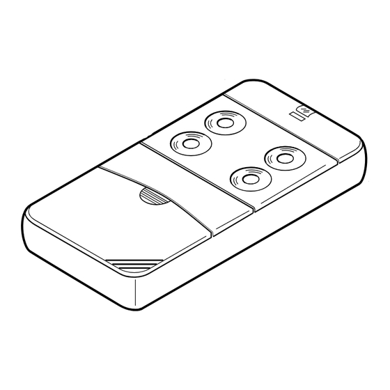
Transmitter versions
S435 TX2
Miniaturised transmitters
S435 TX4
Miniaturised transmitters
S435 TX12
Miniaturised transmitters with switch (12 channels) 4 Buttons
Receiver versions
S435 RXG1CH
Slot-in receiver card (up to 32 codes)
Receiver antenna installation
NB. Minimum and maximum range of the radio controls. 'Range' is intended to
mean the working distance, measured in free space, between the receiver and
the transmitter with the antenna installed. The range is therefore closely linked
to the technical characteristics of the system (power and sensibility) and varies
according to the characteristics of the site in which the system is located.
It therefore follows that to obtain the best results from the radio control the
installation sites for the receiver and the antenna should be carefully chosen.
Note: It is not possible to install 2 receivers at a distance of less than 1.5 mt.
from each other.
Antenna
The installation of the antenna is fundamental, connected to the receiver it represents
the reception point for the radio control.
When installing the antenna the following points should be observed:
The receiver is supplied with its own antenna which consists of a piece of rigid wire
170 mm in length. In alternative it is possible to connect an ANS400 tuned antenna
using a coaxial cable RG58 (impedance 50 Ω) with a maximum length of 15 m.
The antenna should be positioned out of doors in the highest possible point, visible
and away from metal structures.
Receivers
The receiver consists of a card inserted directly into an appliance which is designed
to receive it.
NB. It is good practise to position the receiver away from computer systems, alarm
systems and other possible sources of disturbance. (A bad choice of positioning
could compromise the correct performance of the receiver).
Generating the user code in the transmitters (fig. 1-6)
1) Open the access door (fig.1)
2) For the version equipped with a channel block selection switch choose the desired
block of channels by moving the switch "Y1" (fig.2)
3) Press the button "J1"
4) While keeping button "J1" pressed down press the button "CH" corresponding to
the required channel which is to be memorised (Led "L1" will start to flash) (fig.4).
5) Release the channel button "CH" and the led will carry on flashing (fig.5).
6) Release the button "J1", the led will turn off and the transmitter will memorise the
last code which was transmitted (fig.6).
7) Repeat points 3-4-5-6 for any successive channels
8) To memorise another block of channels move the switch "Y1" to the required
position and repeat the operations 3-4-5-6.
If a code is not generated it could be due to the fact that the memory is empty and
it is therefore impossible to transfer the code to the receiver.
0438/401831
2 Buttons
4 Buttons
1 Channel
CODICE
L253.00
This product has been tried and tested in the manufacturer's laboratory,
during the installation of the product follow the supplied indications
carefully.
Memorising the user code in the receiver (fig. 9)
1) Keep button "P1" pressed down and the led "LD1" will start to flash
2) Transmit the channel which is to be memorised, the led will flash rapidly and the
channel will be memorised. Only one code can be inserted at a time. To insert suc-
cessive codes repeat steps 1 and 2.
If the code is not memorised it could be due to the following:
- The memory is full (32 codes already memorised) and the led remains lit. If this is
the case you can only insert a new code after you have first cancelled an existing one
or after wiping the entire memory (see memory cancelling procedure);
- The code may already exist in memory;
- You have not generated a channel code in the transmitter.
Memory cancelling procedure
To cancel a code proceed as follows:
1) Keep the button "P2" pressed down and the led "LD1" will flash slowly.
2) Transmit the channel which is to be cancelled for at least 3 seconds until the led
starts to flash quickly then repeat points 1 and 2 for any successive channels.
To wipe all the code from memory:
3) Keep buttons "P1" and "P2" pressed down simultaneously for at least 5 seconds
Memory module
This is extractable, furnished with a non volatile EEPROM type memory and contains
the system code. The programmed code is maintained in this module even in the
absence of power.
Channel functions for the S435 radio controls
Channel "A" of the transmitter must always correspond to channel "A" of the receiver
and so forth for all four of the available channels . Remember that the receiver can
only respond to one signal at a time, it therefore follows that several channels cannot
be activated simultaneously.
Receiver
Using the dip switch "D1" select the desired channel by moving only one of the switches
to the "ON" position. The receiver can decode up to 12 different channels in blocks of
3 (A,B,C,D - E,F,G,H - I,L,M,N.) by inserting the jumper "J1" in the right position.
TECHNICAL SPECIFICATIONS
RECEIVER
- reception frequency ............................................... 433,92 Mhz
- local oscillation frequency ................................... 433,42 Mhz
- local oscillation emission ....................................... <57dBm (<2nW)
- intermediate frequency IF ...................................... 500 KHz
- antenna impedance in input .................................. 50 Ω
- sensitivity (finely tuned signal) ............................... 1 µ V
- power supply ........................................................ 24 V dc
- Open collector output with maximum load ........... 50 mA
- maximum power consumption ............................. 20 mA
- operating temperature range ................................. -20°...+60°C
TRASMITTERS
- carrier frequency .................................................... 433.92 Mhz
- carrier frequency tolerance .................................... ±75 Khz
- band width ............................................................. >25 Khz
- apparent radiated power ....................................... -20...-16dBm (10-20µW)
- apparent power harmonic products ...................... <-54 dBm (<4nW)
- modulation ............................................................. AM/ASK
- signal modulation .................................................. PCM, 1.3 ms/bit
- power supply ......................................................... 12V ± 10%
- maximum power consumption .............................. 25 mA
- operating temperature range ................................. - 10÷ +55°C
- relative humidity ..................................................... < 95%
MODELLO
SERIE
435
S
16-05-96
(Alkaline battery GP23A)
DATA
Advertisement

Related Manuals for Cardin Elettronica S Series


Summary of Contents for Cardin Elettronica S Series
- Page 1 DATA MODELLO CODICE SERIE 16-05-96 L253.00 CARDIN ELETTRONICA spa This product has been tried and tested in the manufacturer's laboratory, 31020 San Vendemiano (TV) - Italy during the installation of the product follow the supplied indications Via Raffaello, 36 carefully.
- Page 2 Draft : P.J.Heath Description : Cambia batteria Drawing number : DM0154 CARDIN ELETTRONICA S.p.A - 31020 San Vendemiano (TV) Italy - via Raffaello, 36 Tel: 0438/401818 Fax: 0438/401831 S435 Product Code : S435 Codifica trasmettitore (fig.1) Description : Draft : P.J.Heath...
Need help?
Do you have a question about the S Series and is the answer not in the manual?
Questions and answers