Table of Contents
Advertisement
Available languages
Available languages
OBJ_BUCH-45-001.book Page 3 Tuesday, June 14, 2011 10:56 AM
Svenska
Användarmanual
INNEHÅLLSFÖRTECKNING
/i
1
2
3
4
5
6
7
8
9
Användarmanual - 1.2
1
FÖRORD
Denna användarhandbok behandlar installation,
driftsättning och drift av Spirovent Superior av typerna
3
S6A, S6A-R och S6A-R 2P.
4
Läs alltid anvisningarna noggrant före installation,
6
driftsättning och användning. Behåll anvisningarna för
8
framtida referens.
9
Alla rättigheter förbehållna. Ingen del av denna handbok
15
får mångfaldigas och/eller publiceras via Internet, med
16
tryck, fotokopia, mikrofilm eller på något annat sätt utan
20
föregående skriftligt tillstånd från Spirotech bv.
Denna handbok är sammanställd med största omsorg.
22
Om handboken ändå skulle innehålla någon felaktighet
22
kan Spirotech bv. inte hållas ansvarigt för detta.
1.1
Symboler
Inom anvisningarna används följande symboler:
Varning eller viktigt meddelande
Anmärkning
Risk för elchock
Risk för brännskada
Svenska
3
Advertisement
Chapters
Table of Contents

Related Manuals for Spirotech SpiroVent Superior S6A


Summary of Contents for Spirotech SpiroVent Superior S6A
-
Page 1: Table Of Contents
Spirotech bv. Denna handbok är sammanställd med största omsorg. Garanti Om handboken ändå skulle innehålla någon felaktighet 10 CE-förklaring kan Spirotech bv. inte hållas ansvarigt för detta. Symboler Inom anvisningarna används följande symboler: Varning eller viktigt meddelande Anmärkning Risk för elchock... -
Page 2: Inledning
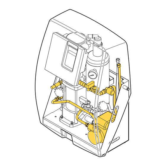
OBJ_BUCH-45-001.book Page 4 Tuesday, June 14, 2011 10:56 AM INLEDNING Översikt över enheten Superior S6A Superior S6A-R 2P Superior S6A-R SmartSwitch Huvudpump Automatisk avluftare Ställbar returventil Avgasningskärl Tryckkännare Intagsslang Tryckomkopplare Påfyllnadsanslutning (typ S6A-R och S6A-R 2P) Tryckmätare Avstängning bakom manometer Styrmodul Skruv Returslang... - Page 3 OBJ_BUCH-45-001.book Page 5 Tuesday, June 14, 2011 10:56 AM Funktion Nedanstående figur ger en schematisk återgivning av enhetens funktion. Bokstäverna korresponderar med huvudfiguren på föregående sida. S6A-R S6A-R 2P Användarmanual - 1.2 Svenska...
-
Page 4: Tekniska Specifikationer
OBJ_BUCH-45-001.book Page 6 Tuesday, June 14, 2011 10:56 AM 2.2.1 Allmänt Enheten ska användas inom gränserna som anges i de Superior är en helautomatisk vakuumavgasare för tekniska specifikationerna, avsnitt 3. vätskefyllda anläggningar. Vätskan innehåller lösta och olösta gaser. Enhetens funktion att avlägsna dessa gaser VARNING från anläggningen tills koncentrationen av olösta gaser når ett absolut minimum. - Page 5 OBJ_BUCH-45-001.book Page 7 Tuesday, June 14, 2011 10:56 AM Allmänna specifikationer S6A-R S6A-R 2P Max. systemvolym 150 - 300 m 150 - 300 m 150 - 300 m Tomvikt 57 kg 59 kg 67 kg Volym avgasningskärl Intagsanslutning Lekare G¾" hona Lekare G¾"...
-
Page 6: Säkerhet
Serial no.: VARNING Year of manufacture: Weight: Det befinner sig heta delar under höljet. Låt Spirotech bv - The Netherlands enheten svalna innan ingreppet påbörjas. CE-markering Enheten är CE-märkt Detta innebär att den har Enhetens typ konstruerats, tillverkats och testats enligt gällande Upptagen effekt säkerhets- och hälsobestämmelser. -
Page 7: Installation Och Driftsättning
OBJ_BUCH-45-001.book Page 9 Tuesday, June 14, 2011 10:56 AM INSTALLATION OCH Installation och montering. DRIFTSÄTTNING OBS! Installationskrav Installera enheten enligt lokalt gällande • föreskrifter och bestämmelser. Enheten skall installeras på en frostfri, väl ventilerad • Installera enheten som en ett delflöde •... - Page 8 OBJ_BUCH-45-001.book Page 10 Tuesday, June 14, 2011 10:56 AM 5.3.1 Montering A Ø10 Ø10 ANMÄRKNING Väggmontering: Montera enheten på väggen med Sett från volymflödets riktning är den första hålen (A). Se till att fästet kan bära den fyllda grenledningen intaget till enheten. enheten (tomvikt + 10 kg).
- Page 9 OBJ_BUCH-45-001.book Page 11 Tuesday, June 14, 2011 10:56 AM Elektriskt OBS! Använd helst ett vägguttag för enhetens • > 70°C strömförsörjning. Detta måste alltid vara åtkomligt. Montera en flerpols huvudströmbrytare • (kontaktöppning >= 3mm) om enheten kopplas direkt till strömförsörjningen. Använd matningskablar med rätt •...
- Page 10 OBJ_BUCH-45-001.book Page 12 Tuesday, June 14, 2011 10:56 AM Om en BMS används, anslut då en BMS-kabel till 5.4.2 Start kontakt J20. Hos typerna S6A-R och S6A-R 2P: Om en extern anordning styr påfyllningen, anslut då en kabel till kontakt J21. Driftsättning 5.4.1 Förberedelser...
- Page 11 OBJ_BUCH-45-001.book Page 13 Tuesday, June 14, 2011 10:56 AM Kontrollera funktionen Fyllning av enheten Starta enheten manuellt, se § 5.5.2. Tryck två gånger på E . Enheten börjar fyllas. NTER Kontrollera värdet på tryckmätaren (B). Detta ska Vänta i 20 sekunder tills Initial fill busy visa över- och undertryck växelvis.
- Page 12 OBJ_BUCH-45-001.book Page 14 Tuesday, June 14, 2011 10:56 AM Tryck på M . Välj User menu > Manual Parameter Beskrivning operation med . Tryck på E NTER Block. Tid dag 2 Se Block.time day 1. Välj Manual operation > system fill med Block.
-
Page 13: Användning
OBJ_BUCH-45-001.book Page 15 Tuesday, June 14, 2011 10:56 AM 5.5.6 Avläsning av data Vid låga vätsketemperaturer kan kondens uppstå på • Följande allmänna uppgifter har lagrats i enhetens vissa platser. Kondensvätskan töms ut genom minne: öppningarna i ramen. Apparattyp Hos typerna S6A-R och S6A-R 2P: •... -
Page 14: Driftsfel
OBJ_BUCH-45-001.book Page 16 Tuesday, June 14, 2011 10:56 AM DRIFTSFEL Tagning ur drift Åtgärder vid driftsfel VARNING Varsko alltid installatören vid driftsfel. • Stäng av spänningen och gör enheten • tryckfri innan ingreppet påbörjas, se §7.2. Ett tryck på O stänger inte av •... - Page 15 OBJ_BUCH-45-001.book Page 17 Tuesday, June 14, 2011 10:56 AM Felsökningstabell Bokstäverna korresponderar med huvudfiguren i § 2.1. En översikt över reservdelarna kan återfinnas i § 8.2. Allmänt Problem Möjlig orsak Årgärd Systemvätskans temperatur är < 0 °C. Sörj för en temperatur på > 0 °C. Err 3 Syst.temp.
- Page 16 OBJ_BUCH-45-001.book Page 18 Tuesday, June 14, 2011 10:56 AM Allmänt Problem Möjlig orsak Årgärd Enheten löper kontinuerligt och Halten av lösta gaser har ännu inte Kontrollera om gaser möjligen kan stängs inte av automatiskt. nått minimum. tränga in. SmartSwitch-omkopplaren (A) är Koppla lös slangen på...
- Page 17 OBJ_BUCH-45-001.book Page 19 Tuesday, June 14, 2011 10:56 AM Särskilt för typerna S6A-R och S6A-R 2P Problem Möjlig orsak Årgärd Läckage föreligger i anläggningen. Reparera läckan. Err 13 Refill freq. too high Kontrollera inställningen Max. Påfyllnad sker för ofta. refill freq. Läckage föreligger i anläggningen.
-
Page 18: Underhåll
OBJ_BUCH-45-001.book Page 20 Tuesday, June 14, 2011 10:56 AM UNDERHÅLL Byt ut den automatiska avluftaren vartannat år. Periodiskt underhåll Byt ut insatsen i magnetventilerna (N) årligen. Reservdelar Bokstäverna korresponderar med huvudfiguren i § 2.1. Artikelnummer Bokstav Beskrivning 15.552 Axelpackning för pump typ CR1-13/1-9 AAA HQQE 15.553 Packningssats för pump typ CR1-9 och CR1-13 15.554... - Page 19 OBJ_BUCH-45-001.book Page 21 Tuesday, June 14, 2011 10:56 AM Underhållslista Typ: Serienummer: Installationsdatum.: Installerad av firma: Installerad av tekniker: Inspektionsdatum: Tekniker: Initialer: Typ av underhåll: Inspektionsdatum: Tekniker: Initialer: Typ av underhåll: Inspektionsdatum: Tekniker: Initialer: Typ av underhåll: Inspektionsdatum: Tekniker: Initialer: Typ av underhåll: Inspektionsdatum: Tekniker:...
-
Page 20: Garanti
OBJ_BUCH-45-001.book Page 22 Tuesday, June 14, 2011 10:56 AM GARANTI Garantin förfaller i fall av felaktig installation, • okunnigt bruk och/eller om obefogad personal försöker utföra reparationer. Garantivillkor Följdskada täcks inte av garantin. • Garantin för Spirotechs produkter gäller till 2 år •... -
Page 21: Preface
Guarantee This manual has been composed with the utmost care. 10 CE statement Should, however, this manual contain any inaccuracies, Spirotech bv cannot be held responsible for this. Symbols Throughout the instructions the following symbols are used: Warning or important note... -
Page 22: Introduction
OBJ_BUCH-45-001.book Page 24 Tuesday, June 14, 2011 10:56 AM INTRODUCTION Overview of the unit Superior S6A Superior S6A-R 2P Superior S6A-R SmartSwitch Main pump Automatic air vent Adjustable outlet valve Deaeration vessel Pressure sensor Inlet hose Pressure switch Refill connection (types S6A-R and S6A-R 2P) Pressure gauge Valve behind pressure gauge Control unit... - Page 23 OBJ_BUCH-45-001.book Page 25 Tuesday, June 14, 2011 10:56 AM Operation The figure below schematically shows the operation of the unit. The letter indications comply with the main figure on the previous page. S6A-R S6A-R 2P User manual - 1.2 English...
-
Page 24: Technical Specifications
OBJ_BUCH-45-001.book Page 26 Tuesday, June 14, 2011 10:56 AM 2.2.1 General The unit should be used within the limits of the technical The Superior is a fully automatic vacuum degasser for specifications as given in chapter 3. installations filled with fluid. The fluid contains dissolved and undissolved gases. - Page 25 OBJ_BUCH-45-001.book Page 27 Tuesday, June 14, 2011 10:56 AM General specifications S6A-R S6A-R 2P Max. system volume 150 - 300 m 150 - 300 m 150 - 300 m Empty weight 57 kg 59 kg 67 kg Volume of degassing vessel Inlet connection Swivel G¾”...
-
Page 26: Safety
Temperature TS: Serial no.: Year of manufacture: Weight: WARNING Spirotech bv - The Netherlands There are hot parts below the cover. Let the unit cool down before starting the activities. CE marking Type of the unit The unit has a CE marking. This means that the unit has... -
Page 27: Installation And Commissioning
OBJ_BUCH-45-001.book Page 29 Tuesday, June 14, 2011 10:56 AM INSTALLATION AND Installation and mounting COMMISSIONING CAUTION Installation conditions Install the unit in accordance with the • local guidelines and rules. Install the unit on a frost-free, well-ventilated place. • Install the unit as bypass on the main •... - Page 28 OBJ_BUCH-45-001.book Page 30 Tuesday, June 14, 2011 10:56 AM 5.3.1 Mounting A Ø10 Ø10 NOTE Wall mounting: Mount the unit on the wall using As seen from the direction of the volume flow, the holes (A). Make sure that the mounting can the first branch is the inlet into the unit.
- Page 29 OBJ_BUCH-45-001.book Page 31 Tuesday, June 14, 2011 10:56 AM Electrical CAUTION Preferably use a wall socket for the • > 70°C power supply to the unit. This should always be accessible. Mount an all-pole main switch (contact • opening >= 3mm) if the unit is directly connected to the power supply.
- Page 30 OBJ_BUCH-45-001.book Page 32 Tuesday, June 14, 2011 10:56 AM If a BMS is used, connect the BMS cable to NOTE connector J20. The pressure in the vessel during the flushing phase should increase from vacuum up to With the types S6A-R and S6A-R 2P: overpressure within 10 seconds.
- Page 31 OBJ_BUCH-45-001.book Page 33 Tuesday, June 14, 2011 10:56 AM Check operation Filling the unit Manually start the unit, see § 5.5.2. Press E two times. The unit starts filling. NTER Check the indication of the pressure gauge (B). This Wait for 20 seconds until Initial fill busy should alternately display overpressure and disappears.
- Page 32 OBJ_BUCH-45-001.book Page 34 Tuesday, June 14, 2011 10:56 AM 5.5.3 Filling the installation Parameter Description Applies to types S6A-R and S6A-R 2P. Block.time day 2 See Block.time day 1. Block.time week Days of the week on which the unit NOTE is not working.
-
Page 33: Use
OBJ_BUCH-45-001.book Page 35 Tuesday, June 14, 2011 10:56 AM 5.5.6 Reading data At low fluid temperatures condensation may occur • The following general data have been stored in the at certain parts. The condensation is drained memory of the unit: through the openings in the frame. -
Page 34: Failures
OBJ_BUCH-45-001.book Page 36 Tuesday, June 14, 2011 10:56 AM FAILURES Putting out of operation Remedy failures WARNING In case of failure always warn the • installer. Remove the voltage and pressure from • the unit before starting the activities see §... - Page 35 OBJ_BUCH-45-001.book Page 37 Tuesday, June 14, 2011 10:56 AM Failure table The letter indications comply with the main figure in § 2.1. An overview of the replacement parts has been included in § 8.2. General Problem Possible cause Correction The temperature of the system fluid is Provide a temperature of >...
- Page 36 OBJ_BUCH-45-001.book Page 38 Tuesday, June 14, 2011 10:56 AM General Problem Possible cause Correction The unit runs continuously and does The content of dissolved gases has Check whether there is a possibility of not switch off automatically. not reached the minimum yet. gases entering.
- Page 37 OBJ_BUCH-45-001.book Page 39 Tuesday, June 14, 2011 10:56 AM Specific for types S6A-R and S6A-R 2P Problem Possible cause Correction There is a leak in the installation. Repair the leak. Err 13 Refill freq. too high Check the setting Max. refill Refilling takes place too frequently.
-
Page 38: Maintenance
OBJ_BUCH-45-001.book Page 40 Tuesday, June 14, 2011 10:56 AM MAINTENANCE Replace the automatic air vent every two years. Periodic maintenance Annually replace the interior of the solenoid valves (N). Replacement parts The letter indications comply with the main figure in §... - Page 39 OBJ_BUCH-45-001.book Page 41 Tuesday, June 14, 2011 10:56 AM Maintenance card Type: Serial number: Installation date: Installed by firm: Installed by technician: Inspection date: Technician: Initials: Nature of the maintenance: Inspection date: Technician: Initials: Nature of the maintenance: Inspection date: Technician: Initials: Nature of the maintenance:...
-
Page 40: Guarantee
Terms of guarantee Consequential damage is not covered by the • guarantee. The guarantee for Spirotech products is valid until 2 • years following the purchasing date. CE STATEMENT 10.1 Declaration of conformity English User manual - 1.2...
Need help?
Do you have a question about the SpiroVent Superior S6A and is the answer not in the manual?
Questions and answers