Table of Contents
Advertisement
Quick Links
Installation Guide
Thank you for purchasing our product.
This manual provides important information about safe and proper
operations of this Switching Hub.
Please read the "Important Safety Instructions" on pages 3 to 5.
Any problems or damage resulting from disassembly of this Switching Hub
by customers are not covered by the warranty.
2-12-7, Higashi-Shimbashi, Minato-ku, Tokyo Japan, 105-0021
©
Switch-M24eG
Model No.
2019
I0716- 10719
PN28240K-TH
PN28240K-MY
PN28240K-ID
PN28240K-SG
Printed in Japan
Advertisement
Table of Contents

Related Manuals for Panasonic Switch-M24eG PN28240K-TH


Summary of Contents for Panasonic Switch-M24eG PN28240K-TH
-
Page 1: Installation Guide
Switch-M24eG Installation Guide PN28240K-TH Model No. PN28240K-MY PN28240K-ID PN28240K-SG Thank you for purchasing our product. This manual provides important information about safe and proper operations of this Switching Hub. Please read the "Important Safety Instructions" on pages 3 to 5. ... -
Page 2: Table Of Contents
Contents Important Safety Instructions Basic Instructions for the Use of This Product 1. Product Outline 1.1 Features 1.2 Specifications 1.3 Accessories 1.4 Basic operation 2. Part Names and Functions 2.1 LED display change 3. Installation and Configuration 3.1 Mounting to rack 3.2 Configuration of IP address (Basic) Troubleshooting 18... -
Page 3: Important Safety Instructions
Important Safety Instructions This chapter contains important safety instructions for preventing bodily injury and/or property damage. You are required to follow them. Severity of bodily injury and/or property damage, which could result from incorrect use of the Switching Hub, are explained below. WARNING This symbol indicates a potential hazard that could result in serious injury or death. - Page 4 WARNING Do not put the Switching Hub into fire. Deviation could lead to explosion and/or fire. Do not insert nor drop any foreign objects such as metal or readily combustible things into the inside through the openings, twisted pair ports, console ports, or SFP extension slots.
- Page 5 CAUTION This Switching Hub is to be periodically serviced in order to maintain its performance. Please choose a product administrator, and have them be sure to implement periodic maintenance. When doing maintenance, check the inspection chart that is posted on our website which has the requisite items listed on it. When using this Switching Hub to design systems, use it after applying ...
-
Page 6: Basic Instructions For The Use Of This Product
SFP extension slot,operation is not guaranteed.For the latest information about compatible SFP extension modules,check our website. 1. Please note that Panasonic shall not bear any liability whatsoever for any damages (this shall include lost earnings, lost opportunities, etc. but this is not restricted to these... -
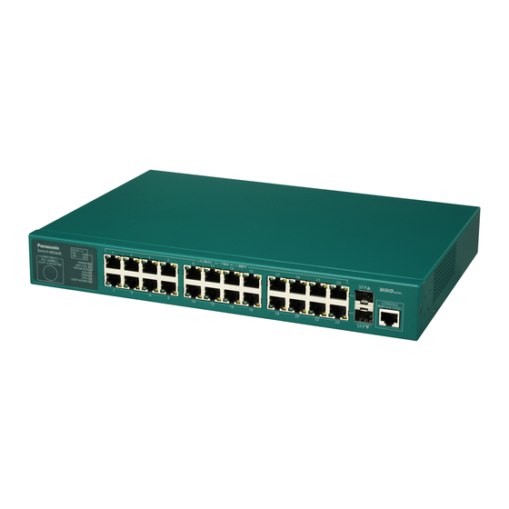
Page 7: Product Outline
Product Outline Switch-M24eG is an all Giga bit Ethernet Switching Hub with management function having 22 ports of 10/100/1000BASE-T and two pairs of 10/100/1000BASE-T port and SFP extension slot, one of which is selectable. 1.1 Features Has wire-speed Layer 2 switching function. Ports 1 to 22 are 10/100/1000BASE-T ports corresponding to autonegotiation. -
Page 8: Specifications
Product Outline 1.2 Specifications Twisted pair port 1-24:RJ45 connecter Interface Transmitting and receiving network system IEEE 802.3 10BASE-T IEEE 802.3u 100BASE-TX IEEE 802.3ab 1000BASE-T Energy Efficient Ethernet function IEEE 802.3az(LPI) SFP extension slot port23,34 Transmitting and receiving network system IEEE 802.3z ※RJ45 or SFP either exclusive use SFF-8472 (DMI:Diagnostic Monitoring Interface) Console port:RJ45 connecter... -
Page 9: Accessories
1.3 Accessories Please be sure to confirm the content. Please contact our distributor if any of the contents are insufficient. Quantity 1 (*) Screw (for fi xing the main unit and the 19 inch rack mount bracket) ... -
Page 10: Part Names And Functions
Part Names and Functions 10/100/1000BASE-T port LED display change button RIGHT LED(ORANGE):LOOP DETECTION SFP▲ Front panel Switch-M24eG POWER ANY COL. CONSOLE LED DISPLAY CHANGE BUTTON 9600.N.8.1(DTE) STATUS/ECO KEEP PRESSING 3SEC ECO MODE ON/OFF GIGA 100M FULL LOOP HISTORY SFP▼ Enlarged view on the next page Explanation label Console port SFP extension slot... - Page 11 Power LED Collision LED Status/ECO mode LED LED display change GIGA mode LED button Speed modeLED DUPLEX mode LED Loop History mode LED POWER (Power) LED Green Light : Power is ON. : Power is OFF. ANY/COL. (Collision) LED Orange Light : During half-duplex operation, packet collision is occurring in either port.
- Page 12 Part Names and Functions Table1. Ports and Port LED lamps 1 to 24 correspond as shown below. Port LED Display mode Behavior Description STATUS/ECO Green Light Link is established. Green Blink Transmitting and receiving data. No device connected. Green Light Link is established at 1000 Mbps.
-
Page 13: Led Display Change
2.1 LED display change ●Display style set by the LED display change button Indication on the front panel and LED lamps RIGHT LED(ORANGE):LOOP DETECTION SFP▲ Switch-M24eG POWER LED DISPLAY ANY COL. CONSOLE CHANGE BUTTON 9600.N.8.1(DTE) STATUS/ECO KEEP PRESSING 3SEC ECO MODE ON/OFF GIGA 100M FULL... - Page 14 Part Names and Functions Switch two types of Base modes and their LEDs in the following way: When Base mode is Status mode (factory default setting) Press "LED DISPLAY CHANGE BUTTON" manually. Automatic Boot Automatically returns to Base mode after 1 minute. Status mode DUPLEX Loop History...
-
Page 15: Installation And Configuration
Installation and Configuration 3.1 Mounting to rack Take out the provided mount brackets (2pcs.)and eight screws (for fixing the mount brackets and the Switching Hub).Fix the mount brackets to the four holes on each side of the Switching Hub using the screws. Then,securely install the Switching Hub on the rack using the four provided screws (for mounting on a 19-inch rack) or screws provided with the rack. -
Page 16: Configuration Of Ip Address (Basic)
Installation and Configuration 3.2 Configuration of IP address (Basic) (1) Connect this Switching Hub and PC with a RJ45–DSub 9-pin console cable and start up the terminal emulator (ZEQUO assist Plus, etc.). (2) Pressing Enter key 3 times opens Login screen. Enter Login name and Password (the default is "manager"... - Page 17 Screen 3 Screen 4 Screen 5 For the following, please see the PDF version Operating Instructions in CD-ROM. - Detailed configuration and management methods using the CLI. - Configuration and management method from ZEQUO assist Plus.
-
Page 18: Troubleshooting
Troubleshooting If you find any problem, please take the following steps to check. LED The POWER LED (Power) is not lit. Check if the power cord is disconnected. Please confirm that the power cord is securely connected to the power port. The Port LED is not lit in Status mode.