JDS Uniphase T-BERD 6000A Testing Manual
Rfc-2544 ethernet
Hide thumbs
Also See for T-BERD 6000A:
- Getting started manual (26 pages) ,
- Getting started manual (4 pages)

Related Manuals for JDS Uniphase T-BERD 6000A


Summary of Contents for JDS Uniphase T-BERD 6000A
- Page 1 Page 1 of 28 JDSU T-BERD 6000A RFC-2544 Ethernet Testing Guide Version 1.0 December 19, 2011 Technical Support tac@jdsu.com 1 866 228-3762 Systems Engineer Dave.Baker@jdsu.com 321-243-0600...
-
Page 2: Table Of Contents
Layer 2 and Layer 3 IPv4 RFC-2544 tests between two T-BERD 6000A’s Layer 2 and Layer 3 IPv4 RFC-2544 tests between the T-BERD 6000A and T-BERD 5800 Layer 2 and Layer 3 IPv4 RFC-2544 tests between the T-BERD 6000A and HST-3000 ... -
Page 3: Overview
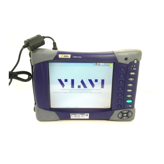
Agreement (SLA). Hardware Description The T-BERD 6000A is a portable test tools for Ethernet testing. The product comes in Ethernet only or Ethernet/T1/T3/SONET variations and works in conjunction with a fiber cleaning and inspection kit to help turn-up and maintain Ethernet links. Menu selections are made from the T-BERD 6000A front panel and touch screen. -
Page 4: Rfc-2544 Test Procedures
SLA metrics. Technicians should follow procedure in one of the following sections, depending on his location (A-side or Z-side) and whether he is using a T-BERD 6000A, T-BERD 5800, or HST- 3000 test equipment. The RFC-2544 test is run from the A-Side. The Z-side is placed in loopback. -
Page 5: T-Berd 6000A Rfc-2544 Test
Fiber Inspection probe. Connect Connect the SFP on the T-BERD 6000A to the Ethernet switch port. Use Orange Multimode jumper cables for 850 nm 1000BASE-SX. Technical Support tac@jdsu.com... - Page 6 Page 6 of 28 Use Yellow Single Mode Fiber jumper cables for 1310 nm 1000BASE-LX and 1550 nm1000BASE-ZX. Use CAT 5E or better cable for copper 1000BASE-TX connections Select Test In the Test menu, select one of the following: ...
- Page 7 Page 7 of 28 For Layer 3 IPv4 testing, configure the following additional settings: Folder Option Value(s) Comment Source IP Type Static Source IP See Work Order Options displayed after tapping Source IP Address field. Default Gateway See Work Order Subnet Mask See Work Order Options displayed after tapping...
-
Page 8: Technical Support
Page 8 of 28 Setup Select the indicated folders and configure your test as follows: Comment Folder Option Value(s) Symmetry Symmetric Throughput, Latency, Tests Packet Jitter, Frame Loss Option only Frame or Packet Frame displayed if test = Layer 3 IPv4 If the MTU is Setup, greater than 1518... - Page 9 At the conclusion of the test, enter Customer name, Technician Name, Test Location, and Comments at the prompt. Select the Append option, and tap [Yes] to save the test report to the T-BERD 6000A hard drive in PDF format. The filename, including a time and date stamp, will be displayed in the Progress log.
- Page 10 Exit Tap [Exit] to return to the main Results view. RFC-6349 If the Z-side test equipment is a T-BERD 6000A and both units are equipped with the LAYER4 TCP Wirespeed option, proceed to section 3. Technical Support tac@jdsu.com...
-
Page 11: T-Berd 6000A Loopback
Page 11 of 28 T-BERD 6000A Loopback Use this procedure to set up a T-BERD 6000A as a far-end (Z-side) loopback device. Step Action Details Install PIM Install the SFP Physical Interface Module (PIM) in the T-BERD 6000A. Insert SFP Insert desired SFP (1000BASE-TX, 1000BASE-SX, 1000BASE-LX, or 1000BASE-ZX) in the MSAM’s SFP PIM. - Page 12 Page 12 of 28 Use Yellow Single Mode Fiber jumper cables for 1310 nm 1000BASE-LX and 1550 nm1000BASE-ZX. Use CAT 5E or better cable for copper 1000BASE-TX connections Select Test In the Test menu, select one of the following: ...
- Page 13 Page 13 of 28 For Layer 3 IPv4 testing, configure the following additional settings: Folder Option Value(s) Comment Source IP Type Static Source IP See Work Order Options displayed after tapping Source IP Address field. Default Gateway See Work Order Subnet Mask See Work Order Options displayed after tapping...
-
Page 14: T-Berd 5800 Loopback
Page 14 of 28 T-BERD 5800 Loopback Use this procedure to set up a T-BERD 5800 as a far-end (Z-side) loopback device. Step Action Details Power On Press the ON/OFF button to turn on the T-BERD 5800. Wait approximately 2 minutes for the Base Unit software to load. Insert SFP For optical testing, insert desired SFP (1000BASE-SX, 1000BASE-LX, or 1000BASE-ZX) in the desired T-BERD 5800’s SFP port. - Page 15 Page 15 of 28 Select Test In the Test menu, select one of the following: For Layer 2 Electrical (Copper) Testing: Ethernet>10/100/1000>Layer 2 Traffic> Terminate. For Layer 2 Optical Testing: Ethernet>1GigE Optical>Layer 2 Traffic> Terminate. For Layer 3 IPv4 Electrical Testing: Ethernet>10/100/1000>Layer 3 Traffic>...
- Page 16 Page 16 of 28 Turn Laser On If testing an Optical link, select the Laser tab in the lower part of the screen and press Laser Off. The button will turn Yellow and be relabeled to indicate the Laser is On. Check LEDs Press the Restart soft key on the Right side of the display to reset test results.
-
Page 17: Hst-3000 Loopback
Page 17 of 28 HST-3000 Loopback Use this procedure to set up an HST-3000 as a far-end Z-side loopback device. Step Action Details Install SIM Install Ethernet Module on the HST-3000. Power On Press the green Power Key to turn on the HST-3000. Wait approximately 25 seconds for the Base Unit software to load. - Page 18 Page 18 of 28 Launch Test App Launch test application as follows: For Layer 2 Electrical (Copper) Testing, press the ETH ELEC Soft key, select Terminate, and press the OK key. Select Layer 2 Traffic at the Test prompt ...
- Page 19 Page 19 of 28 Configure Test Press the Configure Navigation key to configure test setting. Using the Right Arrow key or Settings soft key, scroll through Settings menus and configure your test as follows. Leave all other values at default, unless specified in the Work Order.
- Page 20 Page 20 of 28 Check ARP Status If you are running a Layer 3 IPv4 Test, verify that the final message in the Message bar is “ARP Successful” If “ARP Successful” is not displayed, verify that the HST-3000’s IP menu is configured correctly, as outlined above. Test Inform the A-side technician that you are ready for test.
-
Page 21: Rfc-6349 Test Procedures
Page 21 of 28 RFC-6349 Test Procedures The following procedures describe how to measure Layer 4 TCP throughput with the T-BERD 6000A in accordance with the RFC-6349 benchmarking methodology. The RFC-2544 procedure outlined in Section 2 should be completed prior to RFC-6349 testing. -
Page 22: Jdsu T-Berd 6000A Rfc-6349 Tcp Throughput Test
Page 22 of 28 JDSU T-BERD 6000A RFC-6349 TCP Throughput Test Use this procedure to set up a T-BERD 6000A to test TCP Throughput. Step Action Details Select Test For electrical handoffs: In the Test menu at the top of the Results screen, and select Ethernet>10/100/1000>Layer 4 TCP Wirespeed>... - Page 23 Page 23 of 28 Reset to Defaults In the Tools menu, select Reset Test to Defaults. Press OK to continue. Setup Press the SETUP soft key on the top right side of screen. For Electrical handoffs: Select the indicated folders and configure your test as follows.
- Page 24 Page 24 of 28 Setup Select the Setup tab, select the indicated folders, and configure your test as follows: Comment Folder Option Value(s) Steps RTT only Bottleneck See Work Order for CIR Bandwidth (Mbps) For Layer 2 handoffs, Connect to Server See Work Order set to 192.168.1.3 For Layer 2 handoffs,...
- Page 25 Page 25 of 28 Setup Select the Setup tab, select the indicated folders. and configure your test as follows: Comment Folder Option Value(s) Path MTU, RTT, Walk the Setup, Steps Window, TCP Throughput, All Steps Traffic Shaping Setup, Path MTU Upper Limit See Work Order or enter Maximum (Bytes)
- Page 26 At the conclusion of the test, enter Customer name, Technician Name, Test Location, and Comments at the prompt. Select the Append option, and tap [Yes] to save the test report to the T-BERD 6000A hard drive in PDF format. The filename, including a time and date stamp, will be displayed in the Progress log.
-
Page 27: Jdsu T-Berd 6000A Tcp Server Setup
Page 27 of 28 JDSU T-BERD 6000A TCP Server setup Use this procedure to set up a T-BERD 6000A as a TCP Server. Step Action Details Select Test For Electrical handoffs: In the Test menu at the top of the Results screen, and select Ethernet>10/100/1000>Layer 4 TCP Wirespeed>... - Page 28 Page 28 of 28 Reset to Defaults In the Tools menu, select Reset Test to Defaults. Press OK to continue. Setup Press the SETUP soft key on the top right side of screen. For Electrical Handoffs: Select the indicated folders and configure your test as follows.
Need help?
Do you have a question about the T-BERD 6000A and is the answer not in the manual?
Questions and answers