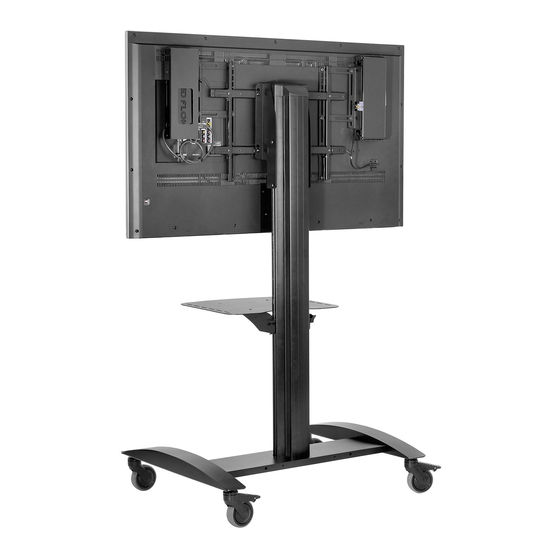
Summary of Contents for peerless-AV WL-SR560M-300
- Page 1 Installation and Assembly: Install prior to attaching adapter brackets to TV Models: WL-SR560M-300 2300 White Oak Circle • Aurora, Il 60502 • (800) 865-2112 • Fax: (800) 359-6500 • www.peerless-av.com 2016-11-17 #180-9092-2 2016-12-06...
- Page 2 NOTE: Read entire instruction sheet before you start installation and assembly. WARNING • Do not begin to install your Peerless product until you have read and understood the instructions and warnings contained in this Installation Sheet. If you have any questions regarding any of the instructions or warnings, for US customers please call Peerless customer care at 1-800-865-2112, for all international customers, please contact your local distributor.
-
Page 3: Parts List
Quick Start Guide for PeerAir Pro Wireless AV Multi-Display System - LIT-0906 HD Flow™ is a trademark of I Do It, LTD. Other parties’ marks are the property of their respective owners. www.peerless-av.com wireless transmitter (1) wireless Receiver (1) plastic stand (1) - Page 4 Wireless Receiver and Power Enclosure Installation NOTE: For mounting patterns smaller than VESA 400, use large enclosure mounting bracket (DD). NOTE: The Wireless Receiver Assembly (AA) and Power Module Assembly (BB) position can be interchanged based on the display’s connector panel location. Install Wireless Receiver Assembly on the side closest to the connector panel.
- Page 5 Installing Adapter Brackets to Universal Plate WARNING • Tighten screws so adapter brackets are fi rmly attached. Do not tighten with excessive force. Overtightening can cause stress damage to screws, greatly reducing their holding power and possibly causing screw heads to become detached.
- Page 6 Begin with longer length screw, hand thread through multi-washer, adapter bracket and spacer in that order into screen as shown below. Screw must make at least three full turns into the mounting hole and fi t snug into place. Do not over tighten. If screw cannot make three full turns into the screen, select a shorter length screw from the baffl...
- Page 7 Wireless Receiver Assembly and Power Module Assembly Setup Remove the two #8 screws securing the cover of the wireless receiver assembly (AA) as shown in detail 4. Open the enclosure to expose the wireless receiver and IR Extender. Remove the M5 x 10mm phillips screws and open the power module assembly (BB) as shown in detail 5.
- Page 8 Locate the IR Extender inside of the wireless receiver enclosure shown in fi gure 19.1. Remove the tie from the cable and position the IR Extender on the display within line of sight of your remote as shown in fi gure 19.2. Remove the adhesive backing from the IR Extender eye and attach to the display.
- Page 9 Install the cable tie anchor (FF) onto the inside Plug the power cord from your display into the triple back wall of the power enclosure (BB). Remove the tap grounded outlet as shown. Coil up the excess adhesive backing from the anchor and press into cord and secure with a cable tie (GG), inserting it place in the area shown.
- Page 10 PeerAir Pro™ Install Guide included. 10 of 11 2016-11-17 #180-9092-2 2016-12-06 © 2014 Peerless Industries, Inc. Peerless-AV® is a registered trademark of Peerless Industries, Inc. All rights reserved. All other brand and product names are trademarks or registered trademarks of their respective owners.
- Page 11 CONTACT INFORMATION Customer Care Need help with installation or set up? Call Peerless-AV Customer Care 1-800-865-2112 (available 7:00am- 7:00pm CST, Monday - Friday), or email us at info@peerless-av.com. Peerless -AV 2300 White Oak Circle Aurora, IL 60502 USA www.peerless-av.com...


Need help?
Do you have a question about the WL-SR560M-300 and is the answer not in the manual?
Questions and answers