
Summary of Contents for Marti Electronics SR–20M
- Page 1 MARTI ELECTRONICS STL RECEIVER MODELS: SR–20M SR–20C October, 2003 IM No. 597–8105...
-
Page 2: Limited Warranty
This warranty is in lieu of all others, either expressed or implied. No representative is authorized to assume for the Seller any other liability in connection with Seller’s products. MAILING & SHIPPING ADDRESS: Broadcast Electronics MARTI Electronics Division 4100 North 24 Street Quincy, IL 62301... - Page 3 Information in this manual is subject to change without notice and does not represent a commitment on the part of Marti Electronics. Marti Electronics may make improvements and/or changes in this manual or in the product described herein at any time.
-
Page 4: About This Manual
ABOUT THIS MANUAL This manual supports both the SR–20M and SR–20C STL receivers for all standard frequency bands. The manual will be revised as new frequency bands become available. Manual Part Numbers: Kit, Binder And Manual: 979–9998 Manual Only 597–8105... -
Page 5: Table Of Contents
TABLE OF CONTENTS Introduction ..............Specifications &... -
Page 6: Introduction
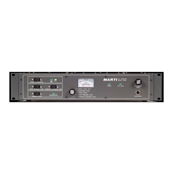
INTRODUCTION See the SPECIFICATIONS & ORDERING section for a listing of available frequency ranges. SR–20M MONO STL RECEIVER SR–20C COMPOSITE STL RECEIVER... - Page 7 The Marti STL Transmitters with companion SR–20C and SR–20M Receivers form a high quality FM, syn- thesized, point–to–point, line of sight, studio–to–transmitter link with two optional sub–channels. A dual link con- sisting of two SR–20M systems for stereo provides two identical broadcast quality channels with better than 70 dB stereo cross–talk and four optional sub–channels.
- Page 8 SR–20M/SR–20C Features: Mechanical – 19 inch rack mount design Wideband operation – 50 MHz SR–20M Models – Monophonic single channel operation within a 50 MHz band SR–40C Models – Composite frequency agile operation within a 50 MHz band Operation from: 1) 85V to 264V, 47 to 63 Hz AC source or 2) an external +10 to +14 VDC source Frequency synthesized dual stage RF converter module with Automatic Frequency Control (AFC)
-
Page 9: Specifications & Ordering
SPECIFICATIONS & ORDERING SR–20M STL Receiver Frequency Bands: See ORDERING INFORMATION below. Type of technology to produce op- Phase–locked loop; synthesized. erating frequency: Operating Temp. Range: –10ºC to +50ºC. Frequency Stability (over operat- 0.0001 %. ing temperature range): SR–20M Signal–to–Noise @ 100 uV: 200 kHz BW @ 50 kHz Dev Greater than 77 dB. - Page 10 SR–20C STL Receiver Frequency Bands: See ORDERING INFORMATION below. Type of technology to produce op- Phase–locked loop; synthesized. erating frequency: Operating Temp. Range: –10ºC to +50ºC. Frequency Stability (over operat- 0.0001%. ing temperature range): Monophonic Signal–to–Noise @ 100 uV: 200 kHz BW @ 50 kHz Dev Greater than 75 dB.
- Page 11 Weight: Net 7.8 pounds.(3.5 kilograms). Dimensions: 3.5 in. high x 19 in. wide x 15 in. deep. (8.9 cm. high x 48.3 cm. wide x 38.1 cm. deep.) Regulatory: FCC, DOC.
-
Page 12: Ordering Information
ORDERING INFORMATION MARTI PART # Description SR20M–150–200 SR–20M Mono STL Receiver, 135 to 185 MHz, Single Channel, 200 kHz Receive Bandwidth, 110/220VAC 50/60 Hz Operation. SR20M–150–125 SR–20M Mono STL Receiver, 135 to 185 MHz, Single Channel, 125 kHz Receive Bandwidth, 110/220VAC 50/60 Hz Operation. -
Page 13: Unpacking & Inspecting
UNPACKING & INSPECTING This equipment was factory tested, inspected, packed, and delivered to the carrier with utmost care. Do not accept shipment from carrier, which shows damage or shortage until the carrier’s agent endorses a state- ment of the irregularity on the face of the carrier’s receipt. Without documentary evidence, a claim cannot be filed. -
Page 14: Installation
INSTALLATION IMPORTANT NOTICE This equipment must be operated in a well–ventilated rack cabinet. Install rack–mounted equipment in a well–ventilated, well–grounded, and shielded rack cabinet. Do not locate solid–state equipment in a rack above tube–type equipment, which produces high temperatures. Problems can also be avoided by locating this unit away from other equipment, which has transformers that produce strong magnetic fields. - Page 15 597–8105–1 COPYRIGHT 2003 MARTI ELECTRONICS, INC FIGURE 1. SINGLE/DUAL SR–20M SYSTEM...
- Page 16 597–8105–2 FIGURE 2. ACCESSORY/REMOTE CONNECTIONS...
- Page 17 SR–20C MONOPHONIC OPERATION CONNECTIONS Refer to Figure 3 as required for the following connections. Connect the receiving antenna coax to the ANTENNA TYPE N port on the rear–panel using a type–N male connector. A short flexible jumper, 20 inches maximum, may be used between the ANTENNA port and the Heliax.
- Page 18 597–8105–8 COPYRIGHT 2003 MARTI ELECTRONICS, INC FIGURE 3. SR–20C SYSTEM DIAGRAM...
- Page 19 Actual bandwidth may require an additional 10% to 15% to allow for the modulation on the subcarrier itself. With severe STL channel crowding with resulting interference prevalent around large markets, subcarriers above 110 KHz are not recommended. For subcarrier operation, connect a Remote Control or Subcarrier Demodulator to the SU1 OUT J1 or SUB2 OUT J3 BNC connectors on the rear–panel.
-
Page 20: Antennas
ANTENNAS CAUTION & WARNING You can be killed if an antenna comes in contact with electric power lines or exposed electrical wiring. For your safety use extreme caution when installing antennas. Keep away from power lines. Î Î Î Î Î Î Î Î...
Need help?
Do you have a question about the SR–20M and is the answer not in the manual?
Questions and answers