Delta AS Series Operation Manual
Hide thumbs
Also See for AS Series:
- Programming manual (1550 pages) ,
- Operation manual (662 pages) ,
- Manual (632 pages)
Table of Contents
Advertisement
Industrial Automation Headquarters
Delta Electronics, Inc.
Taoyuan Technology Center
No.18, Xinglong Rd., Taoyuan City,
Taoyuan County 33068, Taiwan
TEL: 886-3-362-6301 / FAX: 886-3-371-6301
Asia
Delta Electronics (Jiangsu) Ltd.
Wujiang Plant 3
1688 Jiangxing East Road,
Wujiang Economic Development Zone
Wujiang City, Jiang Su Province, P.R.C. 215200
TEL: 86-512-6340-3008 / FAX: 86-769-6340-7290
Delta Greentech (China) Co., Ltd.
238 Min-Xia Road, Pudong District,
ShangHai, P.R.C. 201209
TEL: 86-21-58635678 / FAX: 86-21-58630003
Delta Electronics (Japan), Inc.
Tokyo Office
2-1-14 Minato-ku Shibadaimon,
Tokyo 105-0012, Japan
TEL: 81-3-5733-1111 / FAX: 81-3-5733-1211
Delta Electronics (Korea), Inc.
1511, Byucksan Digital Valley 6-cha, Gasan-dong,
Geumcheon-gu, Seoul, Korea, 153-704
TEL: 82-2-515-5303 / FAX: 82-2-515-5302
Delta Electronics Int'l (S) Pte Ltd.
4 Kaki Bukit Ave 1, #05-05, Singapore 417939
TEL: 65-6747-5155 / FAX: 65-6744-9228
Delta Electronics (India) Pvt. Ltd.
Plot No 43 Sector 35, HSIIDC
Gurgaon, PIN 122001, Haryana, India
TEL : 91-124-4874900 / FAX : 91-124-4874945
Americas
Delta Products Corporation (USA)
Raleigh Office
P.O. Box 12173,5101 Davis Drive,
Research Triangle Park, NC 27709, U.S.A.
TEL: 1-919-767-3800 / FAX: 1-919-767-8080
Delta Greentech (Brasil) S.A.
Sao Paulo Office
Rua Itapeva, 26 - 3° andar Edificio Itapeva One-Bela Vista
01332-000-São Paulo-SP-Brazil
TEL: 55 11 3568-3855 / FAX: 55 11 3568-3865
Europe
Delta Electronics (Netherlands) B.V.
Eindhoven Office
De Witbogt 20, 5652 AG Eindhoven, The Netherlands
TEL : +31 (0)40-8003800 / FAX : +31 (0)40-8003898
AS-0249420-07
*We reserve the right to change the information in this manual without prior notice.
AS Series Operation Manual
2019/12/20
www.deltaww.com
Advertisement
Chapters
Table of Contents
Troubleshooting

Related Manuals for Delta AS Series


Summary of Contents for Delta AS Series
- Page 1 1511, Byucksan Digital Valley 6-cha, Gasan-dong, AS Series Operation Manual Geumcheon-gu, Seoul, Korea, 153-704 TEL: 82-2-515-5303 / FAX: 82-2-515-5302 Delta Electronics Int’l (S) Pte Ltd. 4 Kaki Bukit Ave 1, #05-05, Singapore 417939 TEL: 65-6747-5155 / FAX: 65-6744-9228 Delta Electronics (India) Pvt. Ltd.
-
Page 2: Revision History
AS Series Operation Manual Revision History Ve r s i o n R e v i s i o n D a t e T h e f i r s t v e r s i o n w a s p u b l i s h e d . - Page 3 Ve r s i o n R e v i s i o n D a t e 1 7 . A d d e d d e s c r i p t i o n s o n t h e E r r o r L E D I n d i c a t o r s i n s e c t i o n 1 2 .
- Page 4 Ve r s i o n R e v i s i o n D a t e 2 5 . U p d a t e d S R 8 2 9 i n f o r m a t i o n i n s e c t i o n 1 0 . 5 . 1 . 2 6 .
-
Page 5: Table Of Contents
AS Series Operation Manual Table of Contents Chapter 1 Product Introduction Overview ................... 1-2 1.1.1 Related Manuals ................1-2 1.1.2 Models Descriptions ............... 1-2 Overview ..................1-11 Characteristics ................. 1-12 Chapter 2 Specifications and System Configuration General Specifications ............... 2-3 CPU Module Specifications .............. - Page 6 2.6.4 Positioning Module Device Setting ..........2-56 Counter Module Specifications ............2-57 2.7.1 General Specifications ..............2-57 2.7.2 Counting Module Profiles ............... 2-59 2.7.3 Counting Module Terminals ............2-60 2.7.4 Counting Module Device Setting ............. 2-60 Network Module Specifications ............2-61 2.8.1 General Specifications ..............
- Page 7 Chapter 5 Devices 5.1 Introduction of Devices ................. 5-2 5.1.1 Device Table ................5-2 5.1.2 Basic Structure of I/O Storages ............5-3 5.1.3 Relation Between the PLC Action and the Device Type ......5-4 5.1.4 Latched Areas in the Device Range ..........5-5 5.2.
- Page 8 6.5.2 Basic Editing ─ Creating a Contact and a Coil ........6-9 6.5.3 Basic Editing ─ Inserting a Network and Typing an Instruction .... 6-12 6.5.4 Basic Editing ─ Selection of a Network and Operation ......6-14 6.5.5 Basic Editing ─ Connecting a Contact in Parallel ....... 6-16 6.5.6 Basic Editing ─...
- Page 9 Chapter 8 Hardware Configuration and Data Exchange Setups Hardware Configuration Tool for AS Series Modules - HWCONFIG ..8-2 8.1.1 Introduction of the HWCONFIG Environment .......... 8-2 8.1.2 Configuring a Module ................8-4 Setting the Parameters in an AS Series CPU Module ......8-16 8.2.1 Opening the PLC Parameter Setting Window ........
- Page 10 9.7.2 Create a New Project ................ 9-52 9.7.3 Create a Scanner ................9-54 9.7.3.1 Create a New Ethernet/IP Module ..........9-54 9.7.4 Connect to a Delta Adapter ..............9-56 9.7.5 Editing Corresponding Addresses for AS300 .......... 9-61 9.7.6 Download ..................9-62 9.7.7 Data Mapping ...................
- Page 11 9.8.19 SR Register (Class ID: 359 Hex) ............9-95 Delta EIP Product List ..............9-96 9.9.1 Delta EIP Products ................9-96 9.9.2 Delta EIP Products, DLR (Device Level Ring) supported ......9-96 9.9.3 Delta EIP Products, Scanner supported..........9-96 9.10 Operation and Monitor on the Web ..........
- Page 12 10.3.3 The Predefined Connection Set ............ 10-18 10.4 Sending SDO, NMT and Reading Emergency Message through the Ladder Diagram ..............10-20 10.4.1 Data Structure of SDO Request Message ........10-20 10.4.2 Data Structure of NMT Message ........... 10-23 10.4.3 Data Structure of EMERGENCY Request Message ......10-24 10.4.4 Example of Sending SDO through the Ladder Diagram ....
- Page 13 12.2.9 Other Errors (Without LED Indicators) .......... 12-10 12.3 Troubleshooting for I/O Modules ..........12-18 12.3.1 Troubleshooting for Analog Modules (AD/DA/XA) and Temperature Modules (RTD/TC) ................. 12-18 12.3.2 Troubleshooting for the Positioning Module AS02/04PU ....12-19 12.3.3 Troubleshooting for the High-Speed Counter Module AS02HC ..12-19 12.3.4 Troubleshooting for the Load Cell Module AS02LC ......
- Page 14 A.1 Installing the USB Driver for an AS Series CPU module in Windows XP with SP3 ....................A-2 A.2 Installing the USB Driver for an AS Series CPU module in Windows 7 ... A-6 A.3 Installing the USB Driver for an AS Series CPU module in Windows 8 . A-11 A.4 Installing the USB Driver for an AS Series CPU module in Windows 10.A-13...
- Page 15 Chapter 1 Product Introduction Table of Contents Overview ................... 1-2 1.1.1 Related Manuals ................1-2 1.1.2 Models Descriptions ............... 1-2 Overview ..................1-11 Characteristics ................. 1-12 1 - 1...
-
Page 16: Overview
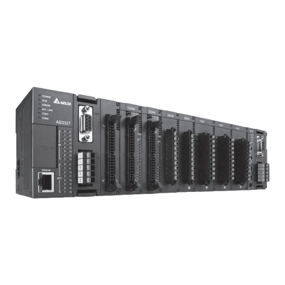
A S S e r i e s O p e r a t i o n M a n u a l 1.1 Overview This manual introduces the AS Series CPU functions, devices, module tables, troubleshooting, and so forth. 1.1.1 Related Manuals The related manuals for AS Series programmable logic controllers are listed below. - Page 17 C h a p t e r 1 P r o d u c t I n t r o d u c t i o n Classification Model Name Description function cards (optional), supporting 24 I/Os (12DI+12DO) and up to 1016 I/Os. Program capacity:128K steps, high- density terminal blocks CPU module, PNP output, 1x Ethernet port , 2x RS-485 ports, 1x USB port, 1x Micro SD interface, 2x function cards...
- Page 18 A S S e r i e s O p e r a t i o n M a n u a l Classification Model Name Description (8DI+6DO+2AI+2AO) and up to 1024 I/Os. Program capacity: 64K steps, removable terminal blocks CPU module, NPN output, 1x Ethernet port , 2x RS-485 ports, 1x USB port, 1x Micro SD interface, CAN AS218TX-A...
- Page 19 C h a p t e r 1 P r o d u c t I n t r o d u c t i o n Classification Model Name Description 16 inputs Spring-clamp terminal block 5 - 30VDC 0.5A/output, 4A/COM AS16AN01P-A 16 outputs Sourcing output...
- Page 20 A S S e r i e s O p e r a t i o n M a n u a l Classification Model Name Description Spring-clamp terminal block 24VDC 8 inputs 5 - 30VDC AS16AP11T-A 0.5A/output, 4A/COM 8 outputs Sinking output Spring-clamp terminal block 24VDC...
- Page 21 C h a p t e r 1 P r o d u c t I n t r o d u c t i o n Classification Model Name Description 8-channel analog input module Hardware resolution: 16 bits AS08AD-B 0 to +10V, 0/1–5V, -5V to +5V, -10V to +10V Conversion time: 2 ms/channel 8-channel analog input module...
- Page 22 A S S e r i e s O p e r a t i o n M a n u a l Classification Model Name Description Resolution: 0.1°C/0.1°F (24 bits) Conversion time: 200ms/channel 8-channel thermocouple Sensor type: J, K, R, S, T, E, N, B and -100 to +100 mV AS08TC-A Resolution: 0.1°C/0.1°F (24 bits) Conversion time: 200ms/channel...
- Page 23 0-10V, 4-20mA (12 bits) Conversion time: 2ms/channel 2x Ethernet ports, supporting MODBUS TCP, EtherNet/IP AS-FEN02 Adapter, AS Series remote control, and DLR function AS-FPFN02 2x Ethernet ports, supporting PROFINET Device (adapter) UC-PRG015-01A Used for the connection between a PLC and a PC via a mini (1.5M)
- Page 24 UC-CMC100-01A (10M) CANopen communication cable, use for AS-FCOPM series UC-CMC200-01A (20M) CANopen communication cable, use for AS-FCOPM series Ethernet communication cable, use for AS Series CPU UC-EMC003-02A (0.3M) modules, AS-FEN02 and AS-FPFN02 Ethernet communication cable, use for AS Series CPU UC-EMC005-02A (0.5M)
-
Page 25: Overview
1.2 Overview An AS series CPU module is an advanced controller with built-in 6 high speed counters for inputs, up to 6-axis (pulse), and can optionally work with a total of 8-axis (CANopen) position outputs. It provides a strong network function for users, and users can create connection among devices on the network through software. -
Page 26: Characteristics
The CPU of the AS Series uses the Soc architecture, built with six (or 3) high speed counters. The maximum frequency is 200 kHz for each counter (differential output models can reach 4 MHz); six- axis high speed position output at 200 kHz (differential output models can reach 4 MHz). - Page 27 (30000 for specific use and 30000 for programming editing), and 64k words of memory (that can be used for storing parameters). Supporting IEC 61131-3 The AS series CPU module supports IEC 61131-3. Supported programming languages are ladder diagrams (LD), sequential function chart (SFC), structured text (ST), and continuous function chart (CFC).
- Page 28 Strong function block Both standard IEC61131-3 function blocks and convenient functions blocks provided by Delta Electronics, Inc. are supported. You can use function blocks for frequently used programs for greater structure and convenience.
- Page 29 Increasing hardware configuration efficiency through a USB cable and ISPSoft The AS Series CPU module provides a standard USB 2.0 interface. USB 2.0 increases the data transfer rate and decreases the time it takes to download the program, monitor the program, and configure the hardware.
- Page 30 (12) I/O module installation The AS Series PLC supports slide-and-lock installation on I/O modules when the power is off. After the PLC is powered off, you can remove the defective module and replace it with a new one without removing other modules.
- Page 31 C h a p t e r 1 P r o d u c t I n t r o d u c t i o n (13) Supporting on-line debugging mode You can use the on-line debugging mode in the AS series CPU module after a single instruction step completes, or after a breakpoint is specified, to find bugs in the program.
- Page 32 A S S e r i e s O p e r a t i o n M a n u a l Step 3: Enter debugging mode (14) On-line editing mode You can use the on-line editing mode when the system is running to update the program without affecting the system operation.
- Page 33 C h a p t e r 1 P r o d u c t I n t r o d u c t i o n After the program is modified and compiled, you can update the program in the CPU module by clicking to download it to the CPU.
- Page 34 A S S e r i e s O p e r a t i o n M a n u a l MEMO 1 - 2 0...
-
Page 35: Chapter 2 Specifications And System Configuration
Chapter 2 Specifications and System Configuration Table of Contents General Specifications ............... 2-3 CPU Module Specifications ..............2-4 2.2.1 Functional specifications ..............2-4 2.2.2 Electrical specifications ..............2-5 2.2.3 CPU Module Profiles ............... 2-8 2.2.4 CPU Module Input/Output Terminals ..........2-13 2.2.5 AS200 Input/Output Terminals ............ - Page 36 C h a p t e r 2 S p e c i f i c a t i o n s a n d S y s t e m C o n f i g u r a t i o Network Module Specifications ............
-
Page 37: General Specifications
A S S e r i e s O p e r a t i o n M a n u a l 2.1 General Specifications Item Specifications Operating temperature -20 to 60°C Storage temperature -40 to 80°C 5–95% Operating humidity No condensation 5–95% Storage humidity... -
Page 38: Cpu Module Specifications
No backplane installation; only module after module Maximum number of modules which can be 32 modules installed Refer to the AS Series 283 tasks (32 cyclic tasks; 16 I/O interrupts; four Number of tasks Operation manual for timed interrupts, etc.) more information. -
Page 39: Electrical Specifications
A S S e r i e s O p e r a t i o n M a n u a l AS228T-A / AS228P-A AS324MT-A / AS332T-A / AS228R-A / AS218TX-A Item Remark AS332P-A AS218PX-A / AS218RX-A for more details on Ethernet specificaitons USB port Mini USB... - Page 40 C h a p t e r 2 S p e c i f i c a t i o n s a n d S y s t e m C o n f i g u r a t i o AS332T-A AS320T-B Model...
- Page 41 A S S e r i e s O p e r a t i o n M a n u a l Electrical specifications for the inputs on AS200 Series. The signals passing through the inputs are 24 VDC signals. Model AS228P-A / AS228R-A / AS228T-A AS218PX-A / AS218RX-A / AS218TX-A Item...
-
Page 42: Cpu Module Profiles
C h a p t e r 2 S p e c i f i c a t i o n s a n d S y s t e m C o n f i g u r a t i o AS228R-A AS228T-A AS228P-A... - Page 43 A S S e r i e s O p e r a t i o n M a n u a l AS320T-B/AS320P-B 9 5 .5 Unit: mm Number Name Description Power LED indicator Indicates the power status of the CPU module Operating status of the module Run LED indicator ON: the module is running.
- Page 44 C h a p t e r 2 S p e c i f i c a t i o n s a n d S y s t e m C o n f i g u r a t i o ...
- Page 45 A S S e r i e s O p e r a t i o n M a n u a l MIL connector, extension cable, and wiring modules (for AS332T-A/AS332P-A/AS324MT-A) 1. Extension Cable UC-ET010-24D (1M) / UC-ET020-24D (2M) / UC-ET030-24D (3M) Length O UT 19 2 0...
- Page 46 C h a p t e r 2 S p e c i f i c a t i o n s a n d S y s t e m C o n f i g u r a t i o Number Name Description...
-
Page 47: Cpu Module Input/Output Terminals
A S S e r i e s O p e r a t i o n M a n u a l 2.2.4 CPU Module Input/Output Terminals AS332P-A AS332T-A X0.15 X0.14 X0.15 X0.14 X0.13 X0.12 X0.13 X0.12 X0.11 X0.10 X0.11 X0.10 X0.9... - Page 48 C h a p t e r 2 S p e c i f i c a t i o n s a n d S y s t e m C o n f i g u r a t i o AS218RX-A/AS218TX-A/AS218PX-A POWER R UN...
- Page 49 A S S e r i e s O p e r a t i o n M a n u a l AS332T-A Y0.0 Y0.2 Y0.4 Y0.6 Y0.8 Y0.10 Y0.12 Y0.14 Y0.1 Y0.3 Y0.5 Y0.7 Y0.9 Y0.11 Y0.13 Y0.15 X0.0 X0.2 X0.4...
-
Page 50: As200 Input/Output Terminals
C h a p t e r 2 S p e c i f i c a t i o n s a n d S y s t e m C o n f i g u r a t i o 2.2.5 AS200 Input/Output Terminals ... -
Page 51: Digital Input/Output Module Specifications
A S S e r i e s O p e r a t i o n M a n u a l 2.3 Digital Input/Output Module Specifications 2.3.1 General Specifications Electrical specifications for the inputs on digital input/output modules (The signals passing through the inputs are 24 VDC signals.) 08AM10N 16AM10N... - Page 52 C h a p t e r 2 S p e c i f i c a t i o n s a n d S y s t e m C o n f i g u r a t i o Model 08AN01 16AN01...
-
Page 53: Digital Input/Output Module Profiles
A S S e r i e s O p e r a t i o n M a n u a l 2.3.2 Digital Input/Output Module Profiles AS08AM10N-A/AS08AN01P-A/AS08AN01R-A/AS08AN01T-A 28.2 08AM 08AN 08AN 08AN Unit: mm Number Name Description Model name Model name of the module If there is an input signal, the input LED indicator is ON. - Page 54 C h a p t e r 2 S p e c i f i c a t i o n s a n d S y s t e m C o n f i g u r a t i o ...
- Page 55 A S S e r i e s O p e r a t i o n M a n u a l AS32AM10N-A 28.2 32AM X0 LED X1 LED Unit: mm Number Name Description Model name Model name of the module X0/X1 LED Switches the LED indicators to their represented inputs.
- Page 56 C h a p t e r 2 S p e c i f i c a t i o n s a n d S y s t e m C o n f i g u r a t i o Number Name Description...
- Page 57 A S S e r i e s O p e r a t i o n M a n u a l AS64AN02T-A 38.2 64AN P WR O UT Unit: mm Number Name Description Model name Model name of the module LED indicator Switches the LED indicators to their represented outputs.
- Page 58 C h a p t e r 2 S p e c i f i c a t i o n s a n d S y s t e m C o n f i g u r a t i o I/O connecting cables UC-ET010-24B (1M) / UC-ET020-24B (2M) / UC-ET030-24B (3M) Length 39 40...
- Page 59 A S S e r i e s O p e r a t i o n M a n u a l AS332T-A/AS64AN02T-A and the external terminal modules UB-10-ID16A, UB-10-OR16A, and UB- 10-OT32A. UB-10-ID16A 67.0 87.0 53.6 Unit: mm ...
- Page 60 C h a p t e r 2 S p e c i f i c a t i o n s a n d S y s t e m C o n f i g u r a t i o ...
-
Page 61: Digital Input/Output Module Terminals
A S S e r i e s O p e r a t i o n M a n u a l 2.3.3 Digital Input/Output Module Terminals AS08AM10N-A AS08AN01P-A 08AN 08AM AS08AN01R-A AS08AN01T-A 08AN 08AN 2 - 2 7... - Page 62 C h a p t e r 2 S p e c i f i c a t i o n s a n d S y s t e m C o n f i g u r a t i o AS16AM10N-A AS16AN01P-A 16AM...
- Page 63 A S S e r i e s O p e r a t i o n M a n u a l AS16AP11P-A AS16AP11R-A 16AP 16AP AS16AP11T-A AS32AM10N-A 1.15 1.14 32AM 16AP 1.13 1.12 X0 LED X1 LED 1.11 1.10 0.15 0.14...
- Page 64 C h a p t e r 2 S p e c i f i c a t i o n s a n d S y s t e m C o n f i g u r a t i o AS32AN02T-A AS64AM10N-A S/S0...
- Page 65 X0.13 X0.15 The wiring module: UB-10-ID32A AS series terminals: Upper X0.0 X0.2 X0.4 X0.6 X0.8 X0.10 X0.12 X0.14 X1.0 X1.2 X1.4 X1.6 X1.8 X1.10 X1.12 X1.14 S/S S/S Lower X0.1 X0.3 X0.5 X0.7 X0.9 X0.11 X0.13 X0.15 X1.1 X1.3 X1.5 X1.7 X1.9 X1.11 X1.13 X1.15 S/S S/S...
- Page 66 Y0.9 Y0.11 Y0.13 Y0.15 UB-10-OT32A AS series terminals: Upper Y0.0 Y0.2 Y0.4 Y0.6 Y0.8 Y0.10 Y0.12 Y0.14 Y1.0 Y1.2 Y1.4 Y1.6 Y1.8 Y1.10 Y1.12 Y1.14 Lower Y0.1 Y0.3 Y0.5 Y0.7 Y0.9 Y0.11 Y0.13 Y0.15 Y1.1 Y1.3 Y1.5 Y1.7 Y1.9 Y1.11 Y1.13 Y1.15 ...
- Page 67 A S S e r i e s O p e r a t i o n M a n u a l AS32AM10N-A/AS32AN02T-A and the wiring modules: UB-10-IO32D 2 - 3 3...
-
Page 68: Analog Input/Output Module Specifications
C h a p t e r 2 S p e c i f i c a t i o n s a n d S y s t e m C o n f i g u r a t i o 2.4 Analog Input/Output Module Specifications 2.4.1 General Specifications ... - Page 69 A S S e r i e s O p e r a t i o n M a n u a l Analog-to-Digital Current Input Conversion Rated Input Range ±20 mA 0 mA–20 mA 4 mA–20 mA K-32000 Rated Conversion Range K+2000 K32000...
- Page 70 C h a p t e r 2 S p e c i f i c a t i o n s a n d S y s t e m C o n f i g u r a t i o Functional specifications Digital-to-analog Voltage output...
- Page 71 A S S e r i e s O p e r a t i o n M a n u a l AS06XA-A Electrical specifications Module name AS06XA-A Number of Inputs: four; Outputs: two inputs/outputs Analog-to-digital Voltage input/Current input; Voltage output/Current output; conversion Supply voltage 24 VDC (20.4 VDC–28.8 VDC) (-15% to +20%)
- Page 72 C h a p t e r 2 S p e c i f i c a t i o n s a n d S y s t e m C o n f i g u r a t i o Analog-to-Digital Current Input Conversion...
-
Page 73: Analog Input/Output Module Profiles
A S S e r i e s O p e r a t i o n M a n u a l Digital-to-Analog Current Output Conversion Rated Output Range 0–20 mA 4–20 mA Conversion Range K32000 K32000 Hardware Output Range -0.2 mA to 20.2 mA 3.8–20.2 mA Error Range... -
Page 74: Analog Input/Output Terminals
C h a p t e r 2 S p e c i f i c a t i o n s a n d S y s t e m C o n f i g u r a t i o Number Name Description... -
Page 75: Analog Input/Output Device Settings
A S S e r i e s O p e r a t i o n M a n u a l AS04DA-A AS06XA-A 06XA 04DA ● 2.4.4 Analog Input/Output Device Settings (1) AS04AD-A 2 - 4 1... - Page 76 C h a p t e r 2 S p e c i f i c a t i o n s a n d S y s t e m C o n f i g u r a t i o (2) AS08AD-B (3) AS08AD-C 2 - 4 2...
- Page 77 A S S e r i e s O p e r a t i o n M a n u a l (4) AS04DA-A (5) AS06XA-A Refer to the AS Series Module Manual for further information on device settings. 2 - 4 3...
-
Page 78: Temperature Measurement Modules Specifications
C h a p t e r 2 S p e c i f i c a t i o n s a n d S y s t e m C o n f i g u r a t i o 2.5 Temperature Measurement Modules Specifications 2.5.1 General Specifications ... - Page 79 A S S e r i e s O p e r a t i o n M a n u a l Functional specifications Analog-to-digital Centigrade (°C) Fahrenheit (°F) Input impedance conversion Pt100: -180°C to +800°C Pt100: -292°F to +1,472°F Ni100: -80°C to +170°C Ni100: -112°F to +338°F Pt1000: -180°C to +800°C...
- Page 80 C h a p t e r 2 S p e c i f i c a t i o n s a n d S y s t e m C o n f i g u r a t i o Functional specifications Analog-to-digital Centigrade (°C)
-
Page 81: Temperature Measurement Module Profiles
A S S e r i e s O p e r a t i o n M a n u a l 2.5.2 Temperature Measurement Module Profiles AS04RTD-A / AS06RTD-A 38.2 04RT D Unit: mm Number Name Description Model name Model name of the module Indicates the status of the power supply... - Page 82 C h a p t e r 2 S p e c i f i c a t i o n s a n d S y s t e m C o n f i g u r a t i o ...
-
Page 83: Temperature Measurement Module Dimensions
A S S e r i e s O p e r a t i o n M a n u a l 2.5.3 Temperature Measurement Module Dimensions AS04RTD-A AS04TC-A 0 4R T D 0 4 TC I1 + S LD I 1- I2 + S LD... -
Page 84: Temperature Measurement Module Device Settings
C h a p t e r 2 S p e c i f i c a t i o n s a n d S y s t e m C o n f i g u r a t i o 2.5.4 Temperature Measurement Module Device Settings AS04RTD-A AS06RTD-A... - Page 85 A S S e r i e s O p e r a t i o n M a n u a l AS04TC-A AS08TC-A Refer to the AS Series Module Manual for further information on device settings. 2 - 5 1...
-
Page 86: Positioning Module Specifications
C h a p t e r 2 S p e c i f i c a t i o n s a n d S y s t e m C o n f i g u r a t i o 2.6 Positioning Module Specifications 2.6.1 General Specifications Electrical specifications for the inputs... - Page 87 A S S e r i e s O p e r a t i o n M a n u a l Model AS04PU-A Item Electrical isolation Optocoupler Input display When the optocoupler is driven, the input LED indicator is ON. Weight 120 g Electrical specifications for the outputs...
-
Page 88: Positioning Module Profiles
C h a p t e r 2 S p e c i f i c a t i o n s a n d S y s t e m C o n f i g u r a t i o 2.6.2 Positioning Module Profiles ... -
Page 89: Positioning Module Terminals
A S S e r i e s O p e r a t i o n M a n u a l 2.6.3 Positioning Module Terminals AS02PU-A AS04PU-A 02PU 04PU ● ● AS02PU-A AS04PU-A Wordings with the same indications that are used Wordings with the same indications that are used on the terminal block and manual on the terminal block and manual... -
Page 90: Positioning Module Device Setting
C h a p t e r 2 S p e c i f i c a t i o n s a n d S y s t e m C o n f i g u r a t i o 2.6.4 Positioning Module Device Setting AS02PU-A AS04PU-A Refer to the AS Series Module Manual for further information on device settings. 2 - 5 6... -
Page 91: Counter Module Specifications
A S S e r i e s O p e r a t i o n M a n u a l 2.7 Counter Module Specifications 2.7.1 General Specifications Item Description Number of channels Phase differential (A/B): x1, x2, x4; CW/CCW; Input signal type Pulse/Direction Pulse Input... - Page 92 C h a p t e r 2 S p e c i f i c a t i o n s a n d S y s t e m C o n f i g u r a t i o Model Pulse input External input...
-
Page 93: Counting Module Profiles
A S S e r i e s O p e r a t i o n M a n u a l Model AS02HC-A Item 5 VDC (±5%), ±100 mA (max.) Voltage / Current ≧ 0.2V OFF→ON Action ≦ level 0.2V ON→OFF... -
Page 94: Counting Module Terminals
CLK1- CLK2- DATA1+ DATA2+ D-sub15 pin DATA1- DATA2- +5VO1 +5VO2 GND1 GND2 Y0.0 Y0.2 Y0.1 Y0.3 COM0 COM1 2.7.4 Counting Module Device Setting Refer to the AS Series Module Manual for further information on device settings. 2 - 6 0... -
Page 95: Network Module Specifications
A S S e r i e s O p e r a t i o n M a n u a l 2.8 Network Module Specifications 2.8.1 General Specifications AS00SCM-A RS-485/RS-422/RS-232 communication interface Item Specifications Connector type European-style terminal block, spring-clamp terminal block 300, 600, 1,200, 2,400, 4,800, 9,600, 19,200, 38,400, 57,600, 76,800, 115,200, Transmission speed 230,400bps... - Page 96 C h a p t e r 2 S p e c i f i c a t i o n s a n d S y s t e m C o n f i g u r a t i o ...
- Page 97 A S S e r i e s O p e r a t i o n M a n u a l Electrical specifications Item Specifications Rated voltage 24 VDC (20.4 VDC~ 28.8 VDC) (9-15%~+20%) Power supply to Maximum load device in IO-Link 0.2A/port current...
-
Page 98: Network Module Profiles
C h a p t e r 2 S p e c i f i c a t i o n s a n d S y s t e m C o n f i g u r a t i o 2.8.2 Network Module Profiles ... - Page 99 A S S e r i e s O p e r a t i o n M a n u a l AS01DNET-A Unit: mm Number Name Description Model name Model name of the module Master/slave mode: NS LED OFF: no power or duplicate ID check has not been completed.
- Page 100 C h a p t e r 2 S p e c i f i c a t i o n s a n d S y s t e m C o n f i g u r a t i o Number Name Description...
- Page 101 A S S e r i e s O p e r a t i o n M a n u a l AS04SIL-A 38.2 04 SI L CQ 1 DI 1 24 V ● Unit: mm Number Name Description Model name Model name of the module...
-
Page 102: Network Module Device Setting
C h a p t e r 2 S p e c i f i c a t i o n s a n d S y s t e m C o n f i g u r a t i o 2.8.3 Network Module Device Setting AS00SCM-A Refer to the AS Series Module Manual for further information on device settings. 2 - 6 8... -
Page 103: Load Cell Module Specifications
A S S e r i e s O p e r a t i o n M a n u a l 2.9 Load Cell Module Specifications 2.9.1 General Specifications AS02LC-A Load cell module Voltage output Rated supply voltage/Power 24 VDC (-15 to +20%) / 5W consumption Minimum/maximum voltage... -
Page 104: Load Cell Module Profiles
C h a p t e r 2 S p e c i f i c a t i o n s a n d S y s t e m C o n f i g u r a t i o 2.9.2 Load Cell Module Profiles ... -
Page 105: Load Cell Module Dimensions
SI G SI G+ C H2 SE N SE N+ SL D 2 4V Unit: mm 2.9.4 Load Cell Module Device Setting AS02LC-A Refer to the AS Series Module Manual for further information on device settings. 2 - 7 1... -
Page 106: Extension Card Specifications
C h a p t e r 2 S p e c i f i c a t i o n s a n d S y s t e m C o n f i g u r a t i o 2.10 Extension Card Specifications 2.10.1 General Specifications ... - Page 107 AS-F232 The AS series PLC is built with COM1 (RS-485), and COM2 (RS-485). You can use this extension card for communication with different interfaces such as RS-232 and a PC. The Communication functions are the same as the built-in ones. You can set the communication port as a slave or a master node. After installing the extension card, go to the HWCONFIG in the ISPSoft for communication setup.
- Page 108 AS-F422 You can use this extension card for communication with Delta HMI series or other devices through the RS-422 communication port. The Communication functions are the same as the built-in ones. You can set the communication port as a slave or a master node. After installing the extension card, go to the HWCONFIG in ISPSoft to set up communication.
- Page 109 A S S e r i e s O p e r a t i o n M a n u a l AS-FEN02 With its own standalone communication port, the extension card can work independently and can be set as a MODBUS TCP server, Client or EtherNet/IP Adapter.
-
Page 110: Extension Card Profiles
C h a p t e r 2 S p e c i f i c a t i o n s a n d S y s t e m C o n f i g u r a t i o ... - Page 111 A S S e r i e s O p e r a t i o n M a n u a l AS-F232/AS-FCOPM AS-F232 AS-FCOPM 23.9 23.9 Unit: mm Pin no. AS-F232 AS-FCOPM CAN_H CAN_L AS-FEN02 25.2 61.5 Number Name...
- Page 112 OFF: a network connection is not established Indicate the status of Ethernet communication ACT indicator X1/X2 Orange BLINKING: data transmission OFF: no data transmission Clip ring Secures AS series RJ-45 Pin Definition 1 TX+ 2 TX- 3 RX+ 4 N/C...
-
Page 113: Function Card Weights
A S S e r i e s O p e r a t i o n M a n u a l RJ-45 Pin Definition 1 TX+ 2 TX- 3 RX+ 4 N/C 5 N/C 6 RX- 7 N/C 8 N/C 2.10.3 Function Card Weights... -
Page 114: Power Supply Module Profiles
Model name of the power supply module Terminal Terminal for wiring +24V: connecting external 24VDC + 24G: connecting external 24G Arrangement of the terminals LG: Line ground L/N: AC power input Power output Connected with AS series 2 - 8 0... -
Page 115: Power Supply Module Terminals
A S S e r i e s O p e r a t i o n M a n u a l 2.11.3 Power Supply Module Terminals AS-PS02 POWER POWER PS02 PS02 L/N: AC power input Line ground INPUT INPUT... - Page 116 C h a p t e r 2 S p e c i f i c a t i o n s a n d S y s t e m C o n f i g u r a t i o MEMO 2 - 8 2...
-
Page 117: Chapter 3 Installing Software
Chapter 3 Installing Software Table of Contents Installing and Uninstalling ISPSoft ............ 3-2 3.1.1 Installing ISPSoft ................3-2 3.1.2 Uninstalling ISPSoft ................ 3-7 Installing and Uninstalling COMMGR ..........3-8 3.2.1 Installing COMMGR ................ 3-8 3.2.2 Uninstalling COMMGR ..............3-10 3 - 1... -
Page 118: Installing And Uninstalling Ispsoft
A S S e r i e s O p e r a t i o n M a n u a l Before developing an AS Series system, install ISPSoft and COMMGR. ISPSoft is a software platform for integrating the hardware, network configuration, and program development for a system. -
Page 119: Installing Ispsoft
Put the ISPSoft CD in the CD-ROM drive, or download the installation program from http://www.delta.com.tw/ch/index.asp. Before you install the installation program downloaded from the website, you must decompress the file. Click Start, and then click Run… to open the Run window. Specify the path to the file called setup.exe in the Open box, and then click OK. - Page 120 A S S e r i e s O p e r a t i o n M a n u a l Type the necessary information in the User Name and Organization boxes, and then click Next. Leave the default path unchanged, or click Change… to change the path. Click Next. Check the installation information, and then click Install.
- Page 121 C h a p t e r 3 I n s ta l l i n g S o ft wa r e 3 - 5...
- Page 122 A S S e r i e s O p e r a t i o n M a n u a l After ISPSoft is installed, the install program creates shortcuts on the desktop and the Start menu. Click Finish to complete the installation.
-
Page 123: Uninstalling Ispsoft
Method 1: Open the Control Panel window, and click Add or Remove Programs. In the Currently installed programs dialog box, click ISPSoft x.xx, and then click Remove. Method 2: Start>Programs>Delta Industrial Automation>PLC>ISPSoft x.xx>Uninstall (2) Click Yes to remove ISPSoft. 3 - 7... -
Page 124: Installing And Uninstalling Commgr
(2) Put a COMMGR CD in the CD-ROM drive, or download the installation program from http://www.delta.com.tw/ch/index.asp. Before you install the program downloaded from the website, you must decompress the file. (3) Click Start, and then click Run… to open the Run window. Specify the path to the file called setupComm.exe in the Open box, and then click OK. - Page 125 C h a p t e r 3 I n s ta l l i n g S o ft wa r e (5) Type the necessary information in the User Name and Organization boxes, and then click Next. (6) Check the installation information, and then click Install. (7) After you install COMMGR, the installation program creates a shortcut to the program on the Start menu.
-
Page 126: Uninstalling Commgr
Method 1: Open the Control Panel window, and click Add or Remove Programs. In the Currently installed programs box, click COMMGR x.xx, and then click Remove. Method 2: Start>Programs>Delta Industrial Automation>Communication>COMMGR>Uninstall (2) Click Yes to remove COMMGR. 3 - 1 0... -
Page 127: Chapter 4 Installing Hardware
Chapter 4 Installing Hardware Table of Contents Installation ....................4-2 4.1.1 Installing a Module ................4-2 4.1.2 Installing a Removable Terminal Block ..........4-4 Wiring ...................... 4-5 4.2.1 Wiring a Power Supply Module ............. 4-5 4.2.2 Wiring I/O Modules ................4-5 4 - 1... -
Page 128: Installation
After you installed the module, fasten the screws on the modules to secure the module on the DIN rail. If there is a vibration source near the installation site, install anti-vibration baffles on the sides of the AS Series modules for better stabilization, such as the gray baffles show below. - Page 129 C h a p t e r 4 I n s ta l l i n g H a r d wa r e Install the baffles: Hook the baffle onto the DIN rail and press it down as the directional arrow shows below. ...
-
Page 130: Installing A Removable Terminal Block
A S S e r i e s O p e r a t i o n M a n u a l The completed baffle installation is shown below. 4.1.2 Installing a Removable Terminal Block Install the removable terminal block on the module as shown below. ... -
Page 131: Wiring
< 2mm 11-12mm 22-18AWG 4.2.2 Wiring I/O Modules The I/O modules include digital input/output, analog input/output, and network modules. Follow the directions for the wiring of I/O modules in Chapter 5 of the AS Series Hardware Manual. 4 - 5... - Page 132 A S S e r i e s O p e r a t i o n M a n u a l MEMO 4 - 6...
- Page 133 Chapter 5 Devices Table of Contents 5.1 Introduction of Devices ................. 5-2 5.1.1 Device Table ................5-2 5.1.2 Basic Structure of I/O Storages ............5-3 5.1.3 Relation Between the PLC Action and the Device Type ......5-4 5.1.4 Latched Areas in the Device Range ..........5-5 5.2.
-
Page 134: Introduction Of Devices
A S S e r i e s O p e r a t i o n M a n u a l 5.1 Introduction of Devices This section describes the values and strings processed by the PLC. It also describes the functions of devices that include input, output, and auxiliary relays, as well as timers, counters, and data registers. -
Page 135: Basic Structure Of I/O Storages
1–31 characters *1: Constants are indicated by K in the device lists in Chapter 5 and Chapter 6 in the AS Series Programming Manual. An example when “K50” appears in the AS Series Programming Manual, enter only the number 50 in ISPSoft. -
Page 136: Relation Between The Plc Action And The Device Type
A S S e r i e s O p e r a t i o n M a n u a l 5.1.3 Relation Between the PLC Action and the Device Type Device type Non-latched area Latched area PLC action Device Y Other devices File register... -
Page 137: Latched Areas In The Device Range
C h a p t e r 5 D e v i c e 5.1.4 Latched Areas in the Device Range Device Function Device range Latched area Input relay X0–X63 All devices are non-latched. Output relay Y0–Y63 All devices are non-latched. Auxiliary relay M0–M8191 The default range is M6000–M8191. -
Page 138: Device Functions
A S S e r i e s O p e r a t i o n M a n u a l Device Functions 5.2. Procedure for processing the program in the PLC: Regenerating the input signal Before executing the program, the external input signal state is read into the memory for the input signal. - Page 139 C h a p t e r 5 D e v i c e The relation among bits, nibbles, bytes, words, and double words in the binary system is shown below. D ouble w ord W ord B Y 3 B Y 2 B Y 1 B Y 0...
- Page 140 A S S e r i e s O p e r a t i o n M a n u a l The following table shows the corresponding values. Binary Number Decimal Number Binary Code Decimal Hexadecimal Number (BIN) (DEC) (BCD) (HEX)
-
Page 141: Floating-Point Numbers
The single-precision floating-point numbers range from ±2-126 to ±2+128, and correspond to the range from ±1.1755×10-38 to ±3.4028×10+38. The AS series PLC uses two consecutive registers to form a 32-bit floating-point number. Take (D1, D0) for example. D1 (b 15 ~b 0) - Page 142 A S S e r i e s O p e r a t i o n M a n u a l Example 2: -23 is represented by a single-precision floating-point number. Converting -23.0 into the floating-point number uses the same steps as converting 23.0 into the floating-point number, except that the sign bit is 1.
-
Page 143: Strings
C h a p t e r 5 D e v i c e 5.2.3 Strings The PLC can process strings composed of ASCII codes (*1). A complete string begins with a start character and ends with an ending character (NULL code). Strings can be a maximum of 31 characters, and the ending character 16#00 is added automatically in ISPSoft. -
Page 144: Input Relays (X)
A S S e r i e s O p e r a t i o n M a n u a l *1: ASCII code chart ... -
Page 145: Output Relays (Y)
5.2.7 Special Auxiliary Relays (SM) Every special auxiliary relay has its own specific function. Refer to section 2.2.7 in the AS Series Programming Manual for more information. -
Page 146: Stepping Relays (S)
A S S e r i e s O p e r a t i o n M a n u a l 5.2.8 Stepping Relays (S) You can easily see the stepping relay in industrial automation to set the procedure. It is the most basic device in sequential function chart (SFC) programming. - Page 147 C h a p t e r 5 D e v i c e A. General-purpose timer When the instruction TMR is executed, the general-purpose timer begins to count. When the value of the timer matches the timer setting value, the output coil is ON. ...
-
Page 148: 16-Bit Counters
A S S e r i e s O p e r a t i o n M a n u a l T1+T2=10 sec X0. 0 SV: K100 T250(PV) Y0. 0 C. Timer used in the function block Use the T412–T511 timers for the function block or the interrupt. When the instruction TMR or END is executed, the timer used in the functional block begins to count. - Page 149 C h a p t e r 5 D e v i c e Item 16-bit counter The contact is ON when the value of the counter matches the setting Output contact value. When the instruction RST is executed, the current value is cleared to Reset zero, and the contact is reset to OFF.
-
Page 150: 32-Bit Counters (Hc)
A S S e r i e s O p e r a t i o n M a n u a l When X0.0=ON, the instruction RST will be executed and the current value of C0 will be reset to zero and the output contact of the counter C0 will be FF. - Page 151 If the counter counts up from 2,147,483,647, the next current value is -2,147,483,648. If the counter counts down from -2,147,483,648, the next current value is 2,147,483,647. 32-bit high speed addition/subtraction counter Refer to the DCNT instruction description (API 1004) in the AS Series Programming Manual for more details. Example: 5 - 1 9...
-
Page 152: Data Registers (D)
A S S e r i e s O p e r a t i o n M a n u a l X10.0 drives SM621 to determine counting direction (up/down) of HC0. When X11.0 goes from OFF to ON, RST instruction executes, the PV in HC0 is cleared to 0, and its contact is OFF. -
Page 153: Special Data Registers (Sr)
ISPSoft > HWCONFIG > Module > Device Setting > Normal Exchange Area to see the data register range. 5.2.13 Special Data Registers (SR) Every special data register has its definition and specific function. Refer to section 2.2.14 in the AS Series Programming Manual for more information. 5.2.14 Index Register (E) The index register is a 16-bit data register. - Page 154 A S S e r i e s O p e r a t i o n M a n u a l MEMO 5 - 2 2...
-
Page 155: Chapter 6 Writing A Program
Chapter 6 Writing a Program Table of Contents Quick Start ..................6-2 6.1.1 Example ..................6-2 6.1.2 Hardware ..................6-2 6.1.3 Program ..................6-3 Procedure for Creating a Project in ISPSoft ........6-3 Creating a Project ................6-4 Hardware Configuration ..............6-5 6.4.1 Configuring a Module .............. -
Page 156: Quick Start
When the sensor value is 100, the internal completion flag is set to ON. The flag state can be used by other procedures later. However, this example does not introduce the use of flag states. 6.1.2 Hardware In this example, the AS series CPU module used is the AS332T-A. Type Description Digital input X0.0... -
Page 157: Program
Hardware configuration You set the parameters such as a range of latched devices and a port number in a PLC. You configure the modules with an AS Series CPU module, and set the parameters in these modules. Network configuration If a system uses a network architecture, or devices need to exchange data, use the network configuration tool NWCONFIG in ISPSoft to configure a network and exchange data with COM as well as Ethernet. -
Page 158: Creating A Project
A S S e r i e s O p e r a t i o n M a n u a l 6.3 Creating a Project After you start ISPSoft, on the File menu, point to New, and then click New to create a new project. You can also create a new project by clicking on the toolbar after you start ISPSoft. -
Page 159: Hardware Configuration
C h a p t e r 6 W r i t i n g a P r o g r a m 6.4 Hardware Configuration After you double-click HWCONFIG in the project management area, the HWCONFIG window appears. 6.4.1 Configuring a Module In the HWCONFIG window, the default setting is with a CPU module. - Page 160 A S S e r i e s O p e r a t i o n M a n u a l Click the setting tabs for specific parts of the setup at the top of the window and then select the setting items on the left for configuration.
-
Page 161: Creating A Program
C h a p t e r 6 W r i t i n g a P r o g r a m 6.5 Creating a Program The following sections show you how to create a traditional ladder diagram in ISPSoft. The sections include creating a POU, editing a traditional diagram, and compiling a program. - Page 162 A S S e r i e s O p e r a t i o n M a n u a l (3) After you add the POU, a program editing window appears in the main working area. Loc al s ymbol table Program editing area After the program editing window opens, the corresponding toolbar appears in the window.
-
Page 163: Basic Editing ─ Creating A Contact And A Coil
C h a p t e r 6 W r i t i n g a P r o g r a m Icon Keyboard shortcut Function Typing an instruction Inserts a coil Typing an instruction Inserts a comparison contact Typing an instruction Selects a type of comparison contact Inserts a block logic instruction... - Page 164 A S S e r i e s O p e r a t i o n M a n u a l (2) Click on the toolbar, or press Esc on the keyboard. After you double-click the contact, a list appears. The items on the list are Normally Open, Normally Close, Rising-edge Trigger, and Falling-edge Trigger.
- Page 165 C h a p t e r 6 W r i t i n g a P r o g r a m (4) Click on the toolbar, or press Esc on the keyboard. After you double-click the coil, a list appears. The items on the list are Out, Set, and Reset.
-
Page 166: Basic Editing ─ Inserting A Network And Typing An Instruction
A S S e r i e s O p e r a t i o n M a n u a l Additional remark After you click a network and press Enter on the keyboard, you can edit a box. Press Enter on the keyboard to edit the next box in the network. - Page 167 C h a p t e r 6 W r i t i n g a P r o g r a m (2) Type the IL instruction “LD M0”. This instruction is not case-sensitive. As soon as you type the IL instruction, a box which you can edit appears.
-
Page 168: Basic Editing ─ Selection Of A Network And Operation
A S S e r i e s O p e r a t i o n M a n u a l To insert a normally-closed contact (contact B), type “B <device address>” To insert an output coil (OUT), type “O <device address>” Basic Editing ─... - Page 169 C h a p t e r 6 W r i t i n g a P r o g r a m To select several networks, press and hold the Ctrl key on the keyboard and click the networks. You can also select a range of networks by pressing and holding Shift on the keyboard, clicking the first network within the range, and then clicking the last network within the range.
-
Page 170: Basic Editing ─ Connecting A Contact In Parallel
A S S e r i e s O p e r a t i o n M a n u a l Proceed with the steps in the example below. (1) Select Network 1, then right-click Network 1, and then click Copy. (2) Select Network 2, right-click Network 2, and then click Paste. -
Page 171: Basic Editing ─ Editing A Comment
C h a p t e r 6 W r i t i n g a P r o g r a m (2) Write the program in Network 2 shown below. Additional remark After you select a group of contacts, connect a contact to the group of contacts as described above. 6.5.6 Basic Editing ─... -
Page 172: Basic Editing ─ Inserting An Applied Instruction
A S S e r i e s O p e r a t i o n M a n u a l (3) Write the program shown below. 6.5.7 Basic Editing ─ Inserting an Applied Instruction Add Network 6 under Network 5, and then write the program shown below. Insert an applied instruction in one of the three ways described below. - Page 173 C h a p t e r 6 W r i t i n g a P r o g r a m Method 2 Click APIs in the project management area and find the instruction type. Click the instruction (INC in this example) that you want to insert, and then drag it to the desired position. ...
-
Page 174: Basic Editing ─ Creating A Comparison Contact And Typing A Constant
A S S e r i e s O p e r a t i o n M a n u a l After you insert the instruction, assign a device address to the operand, and write the program shown below. -
Page 175: Writing A Program
C h a p t e r 6 W r i t i n g a P r o g r a m Write the program shown below. In ISPSoft, K precedes a decimal value and H precedes a hexadecimal value. To type a decimal value in ISPSoft, type it directly. -
Page 176: Checking And Compiling A Program
A S S e r i e s O p e r a t i o n M a n u a l *1. The program above saves in the folder …\ISPSoft x.xx\Project\Example\Gluing_System_C. *2. Refer to Chapter 8 in the ISPSoft User Manual for more information about creating a ladder diagram. 6.5.10 Checking and Compiling a Program After you write a program, check the syntax of the programming language or compile the program. - Page 177 C h a p t e r 6 W r i t i n g a P r o g r a m Check From the Compile menu, click Check, or on the toolbar. ompile From the Compile menu, click Compile, or on the toolbar.
-
Page 178: Testing And Debugging A Program
CPU module. (2) Connect the CPU module to the computer with a USB cable. If the USB driver for the AS series CPU module is installed on the computer, Delta PLC appears in the Device Manager window, and a port number is assigned to Delta PLC. - Page 179 C h a p t e r 6 W r i t i n g a P r o g r a m (5) Set the parameters in the Driver Properties dialog box, and then click OK. Type a driver name in the Driver Name box. Select USB (Virtual COM) in the Type list in the Connection Setup section.
-
Page 180: Downloading A Program And Parameters
A S S e r i e s O p e r a t i o n M a n u a l (8) On the PLC menu, click System Information. ISPSoft retrieves related information from the PLC. If the computer communicates with the CPU module normally, the related information retrieved from the PLC displays in the System Information dialog box. - Page 181 C h a p t e r 6 W r i t i n g a P r o g r a m Downloading the hardware configuration (1) Double-click HWCONFIG in the project management area to open the HWCONFIG window. (2) The hardware configuration displays in the window.
-
Page 182: Connection Test
A S S e r i e s O p e r a t i o n M a n u a l Downloading the program After the program compiles, on the PLC menu point to Transfer, and then click Download. You can also click on the toolbar after the program compiles. - Page 183 C h a p t e r 6 W r i t i n g a P r o g r a m In the online monitoring mode, you can view the present scan time, the communication status, and the status of the PLC in the status bar in ISPSoft.
- Page 184 A S S e r i e s O p e r a t i o n M a n u a l Before you change the status of a device, make sure the operation does not cause damage to equipment or personnel.
- Page 185 C h a p t e r 6 W r i t i n g a P r o g r a m The list below describes the Enter Present Value dialog box. Message Type a value in the Present Value box. ...
- Page 186 A S S e r i e s O p e r a t i o n M a n u a l However, you can force an input contact ON or OFF during a test. Click an input or output contact to set, right-click the contact, point to Force, and click On (X/Y), Off (X/Y), Release (X/Y), or Release All.
- Page 187 C h a p t e r 6 W r i t i n g a P r o g r a m Method 2 Right-click Device Monitoring Table in the project management area, and click New. Type a table name in the Add Monitor Table dialog box, and then click OK. An item appears under Device Monitor Table in the project management area.
- Page 188 A S S e r i e s O p e r a t i o n M a n u a l Press Insert on the keyboard to switch between inserting and replacing an item in the monitoring table. The selected mode displays in the status bar in ISPSoft.
- Page 189 C h a p t e r 6 W r i t i n g a P r o g r a m Column Description Data type Data type of a monitored symbol. Value (16 bits) In online mode, displays a 16-bit value. Value (32 bits) In online mode, displays a 32-bit value.
-
Page 190: Setting A Real-Time Clock
A S S e r i e s O p e r a t i o n M a n u a l Setting a Real-time Clock After you connect an AS Series CPU module to a computer, you can set the real-time clock in the CPU module through ISPSoft. -
Page 191: Chapter 7 Memory Card
Chapter 7 Memory Card Table of Contents Overview of Memory Cards ..............7-2 7.1.1 Appearances of Memory Cards ............7-2 7.1.2 Memory Card Specifications ............7-2 Before using a Memory Card .............. 7-3 7.2.1 Formatting a Memory Card ............. 7-3 Installing and Removing a Memory Card ........... -
Page 192: Overview Of Memory Cards
SD cards are also classified into three types according to capacity: SD cards, SDHC cards, and SDXC cards. The AS Series currently only supports a maximum of 32GB in FAT32 format. SD card families are shown in the table below. The Micro SDHC in the SDHC column indicates the specifications supported by the AS Series. -
Page 193: Before Using A Memory Card
You may need to format a new SDHC memory card with the FAT32 file system before you use it for the first time. You cannot use an unformatted SDHC memory card in an AS Series CPU module. The following example introduces the most common way to format an SDHC card: formatting an SDHC card through a card reader. -
Page 194: Installing A Memory Card
A S S e r i e s O p e r a t i o n M a n u a l 7.3.2 Installing a Memory Car Insert a memory card into the CPU module memory card slot and push it in until it clicks. Be sure the memory card is fixed firmly in the slot;... -
Page 195: Folder Structure In A Memory Card
C h a p t e r 7 M e m o r y C a r d 7.4.2 Folder Structure in a Memory Card The image below shows the default folder group created by an AS System. The folder name is AS200/300. Several subfolders are contained inside the AS200/300 folder. -
Page 196: Introduction To The Card Utility
The list below describes the functions supported by the CARD Utility, including a flowchart. If you export data from an AS Series CPU module as a backup file (*.dup), you can save the exported data in the memory card in the module or in a folder on the computer. You can also decide whether to back up the values in the devices in the AS Series CPU module. - Page 197 C h a p t e r 7 M e m o r y C a r d After selecting Double-click CARD Utility in the project management area to open the CARD Utility wizard. the controller type, click “Next” to proceed. 7 - 7...
-
Page 198: Backing Up A Project
7.6 Backing Up a Project If the backup source or backup destination is an AS Series CPU module or memory card, make sure that ISPSoft is connected to the AS Series CPU module. During backup, the CPU LED and Error LED blinks alternatively and SM452 flag is ON. - Page 199 After you select CPU (Need Connection) / ISP Project (Compiled and saved), click Next, a. If you select the CPU (Need Connection), a prompted window appears. And you need to decide whether to back up the values in devices on the AS Series CPU module that is connected to ISPSoft. 7 - 9...
- Page 200 A S S e r i e s O p e r a t i o n M a n u a l b. If you select the ISP Project (Compiled and saved), the backup file is stored in your computer. Click and select an isp file in the Open dialog box and then decide the file path where you’d like to store the backup file in your computer and then define its file name.
- Page 201 C h a p t e r 7 M e m o r y C a r d If you select PC (DUP File), click , select a folder in the Save in list in the Save As dialog box, and type a filename in the File name box.
- Page 202 A S S e r i e s O p e r a t i o n M a n u a l The AS Series CPU module still performs the data backup even if you click Cancel. You can turn off the AS Series CPU module to stop the data backup;...
-
Page 203: Restoring A Project
7.7 Restoring a Project If the restoration source or restoration destination is an AS Series CPU module or memory card, make sure that ISPSoft is connected to the AS Series CPU module. During restoration, the CPU LED and Error LED blinks alternatively and SM452 flag is ON. - Page 204 A S S e r i e s O p e r a t i o n M a n u a l If you select PC (Need Connection), the backup files in the PC display in a window after you click .
- Page 205 (3) Select a restoration destination, and then click Next. To put the selected backup file into the AS Series CPU module, select CPU (Need Connection). If the restoration source is the CPU (Need Connection), the restoration destination must be the AS Series CPU module.
- Page 206 The AS Series CPU module still performs the data restoration even if you click Cancel in the process of restoring a backup file in the memory card. You can turn off the AS Series CPU module to stop the data restoration from being performed. To prevent the AS Series CPU module from operating incorrectly, restore the AS Series CPU module to the factory setting, or perform the data restoration again.
-
Page 207: Restoration Starts Once Cpu Is Supplied With Power
C h a p t e r 7 M e m o r y C a r d Computer The ID and the password in the backup file become the program ID and the ISPSoft project project password in the ISPSoft project. (5) After you perform the data restoration, click Home or Close in the CARD Utility wizard. -
Page 208: Cpu Error Log
A S S e r i e s O p e r a t i o n M a n u a l CPU Error Log The system stores CPU error messages in the memory card whenever the quantity of the error messages reached to 20. -
Page 209: Ethernet
9.1.1 EtherNet/IP .................. 9-4 9.1.2 Definitions of Common Network Terms ..........9-4 9.1.3 Ethernet Features ................. 9-5 9.1.3.1 Delta EIP Architecture ..............9-5 9.1.3.2 EIP Features ................9-6 Installation ..................9-6 9.2.1 EtherNet/IP Device................ 9-6 9.2.2 Network Cable Installation ............. 9-6 9.2.2.1. - Page 210 9.8.18 SM Register (Class ID: 358 Hex) ............9-94 9.8.19 SR Register (Class ID: 359 Hex) ............9-95 Delta EIP Product List ..............9-96 9.9.1 Delta EIP Products ................9-96 9.9.2 Delta EIP Products, DLR (Device Level Ring) supported ......9-96 9 - 2...
- Page 211 Diagnostic ................9-109 9.10.5.1 Hardware Status Page ............9-109 9.10.6 Configurations ................9-111 9.10.6.1 Save Configuration Page ............9-111 9.11 Delta EIP Product Application (with OMRON Products) ....9-111 9.11.1 Architecture ................9-111 9.11.2 TAG Connection ................. 9-112 9.11.3 IO Connection ................9-128...
-
Page 212: Chapter 9 Ethernet/Ip
Factory Automation (FA), Building Automation (BA), Process Automation (PA) and many more. Delta covers a full range of controller and drive products supported by EtherNet/IP, including Programmable Logic Controllers (PLC), inverters, Human Machine Interfaces (HMI) and so on. Refer to Section 9.9 for a full product list that support EtherNet/IP. -
Page 213: Ethernet Features
This typical Delta EIP architecture includes an EIP Scanner and Adapters; data mapping is achieved between devices through an I/O connection and explicit messaging. The AS Series supports single port Ethernet; thus you can install and configure devices with embedded switch technology over EtherNet/IP. -
Page 214: Eip Features
EIP device includes the EIP Builder software, EIP Scanner, EIP Adapter, EIP Tap, and an Ethernet switch. EIP Scanners and EIP Adapters can be further divided into single port and dual port devices. The AS Series are single port devices. -
Page 215: Single Port Device
C h a p t e r 9 E t h e r n e t S p e c i f i c a t i o n a n d O p e r a t i o n 9.2.2.1. - Page 216 Ring Topology A DLR function is required to create a ring topology. Refer to Section 9.9.2 for AS series that support DLR. When a switch is needed for the particular topology, the switch should support the DLR function. If not, the connection might fail.
-
Page 217: Eip Builder Software
C h a p t e r 9 E t h e r n e t S p e c i f i c a t i o n a n d O p e r a t i o n 9.2.2.3 EIP Builder Software Linear and star topology Install the EIP Builder software on your PC to monitor and configure the EIP devices. -
Page 218: Specifications
A S S e r i e s O p e r a t i o n M a n u a l 9.3 Specifications 9.3.1 Ethernet Specification Model AS300 & AS200 Series EtherNet/IP Scanner / Adapter、MODBUS TCP Communication Protocols Protocols BOOTP, DHCP, SMTP, NTP, Socket, HTTP Communication Speed... - Page 219 C h a p t e r 9 E t h e r n e t S p e c i f i c a t i o n a n d O p e r a t i o n *1: The maximum connection quantity is the sum of client connections and server connections.
-
Page 220: Profinet Specification
A S S e r i e s O p e r a t i o n M a n u a l Item AS300 Series AS200 Series Remarks Number 500 bytes (IO Connection) Max. Data Length 400 bytes (Explicit Message) Requested Packet 5 ms –... -
Page 221: Ethernet Communication Port
Run the EIP Builder You can call EIP Builder from Delta EIP Scanner’s HWCONFIG in ISPSoft. You can also call it independently to set up parameters for the Adapter. The Delta EIP Scanner is equipped with the EtherNet/IP communication PLC and the EtherNet/IP module. -
Page 222: Run The Eip Builder Via An Eip Scanner
Steps to run EIP Builder Run EIP Builder from an EIP Scanner product. When using a Delta EIP Scanner, you set up an EIP module through HWCONFIG in ISPSoft. Make sure the current communication is via EtherNet in ISPSoft. - Page 223 C h a p t e r 9 E t h e r n e t S p e c i f i c a t i o n a n d O p e r a t i o n Open HWCONFIG: double-click HWCONFIG in the Project window.
-
Page 224: Set Up The Ip Address
9.4.2 Set up the IP Address This section provides an overview of how to set up IP address for AS Series modules. Set up the IP address before configuring the EIP related parameters or data mapping settings. 9.4.2.1 IP Address Types The AS Series supports 3 types of IP addressing, BOOTP, DHCP and static IP address. - Page 225 C h a p t e r 9 E t h e r n e t S p e c i f i c a t i o n a n d O p e r a t i o n Save and download the settings from HWCONFIG: on the File menu click Save to save the settings and then on the Options menu, click Download or click the Download button on the toolbar.
- Page 226 A S S e r i e s O p e r a t i o n M a n u a l Descriptions for the IP Manager: Item Definition Stops the BOOTP/DHCP server; the IP manager does not request an IP ...
- Page 227 C h a p t e r 9 E t h e r n e t S p e c i f i c a t i o n a n d O p e r a t i o n ...
- Page 228 A S S e r i e s O p e r a t i o n M a n u a l Set up the IP address Double-click the listed MAC address for your device to open the Input Data dialog box. ...
- Page 229 9.4.2.4 Re-enable BOOTP/DHCP To enable the DHCP or BOOTP function again, use the device software to make the change. Using the AS Series as an example: from the Start menu, start ISPSoft, then HWCONFIG, and then IP Manager. In IP Manager sets the IP address to the receiving mode.
- Page 230 A S S e r i e s O p e r a t i o n M a n u a l ◆ Double-click the device to open the Device Setting dialog box. ◆ Make changes to the items, such as IP address receiving modes and click OK to confirm the settings. Download the settings from HWCONFIG ◆...
-
Page 231: Network
C h a p t e r 9 E t h e r n e t S p e c i f i c a t i o n a n d O p e r a t i o n 9.4.3 Network EIP Builder provides a graphical user interface, and you can see the devices and their EtherNet/IP connections in the... - Page 232 A S S e r i e s O p e r a t i o n M a n u a l Toolbar buttons Icon Name Definition Creates a new EIP Builder project Open Opens an existing project Save Saves the project Help...
- Page 233 C h a p t e r 9 E t h e r n e t S p e c i f i c a t i o n a n d O p e r a t i o n ...
- Page 234 A S S e r i e s O p e r a t i o n M a n u a l 9.4.3.1 Scan Network Name Definition Selection checkboxes Select the devices you want to add to the network view. ...
- Page 235 C h a p t e r 9 E t h e r n e t S p e c i f i c a t i o n a n d O p e r a t i o n Click the Scan Network button to scan the network and list the scanned devices in the Device List dialog box.
- Page 236 A S S e r i e s O p e r a t i o n M a n u a l 9.4.3.2 Add devices (Manually) Steps to add new devices manually Select the devices to add from the Product List. You can also enter the module name in the search bar. Drag the device onto the Network View.
- Page 237 C h a p t e r 9 E t h e r n e t S p e c i f i c a t i o n a n d O p e r a t i o n (b) Create network connections for the devices.
- Page 238 A S S e r i e s O p e r a t i o n M a n u a l 9.4.3.3 Set EIP parameters Click the tabs in the Information window to view and edit the EIP Parameter and the EDS Parameter. ...
- Page 239 C h a p t e r 9 E t h e r n e t S p e c i f i c a t i o n a n d O p e r a t i o n When the device is connected, you can click the Upload button to upload the related parameters from the device.
-
Page 240: Data Mapping
A S S e r i e s O p e r a t i o n M a n u a l EDS Parameter Tab: this is not supported for the AS Series modules; the software closes itself when this Tab is selected. - Page 241 C h a p t e r 9 E t h e r n e t S p e c i f i c a t i o n a n d O p e r a t i o n Name Definition ...
- Page 242 A S S e r i e s O p e r a t i o n M a n u a l I/O Mapping Table Delta EIP devices provide an I/O mapping table. You can use the table to edit the parameters if needed. Name Definition Select the connection from the list.
- Page 243 C h a p t e r 9 E t h e r n e t S p e c i f i c a t i o n a n d O p e r a t i o n ...
- Page 244 A S S e r i e s O p e r a t i o n M a n u a l Steps to set up and download parameters Create a data mapping table (*): Right-click the COM port on the Ethernet Scanner, and then click Data Mapping to open the Data Mapping Table.
- Page 245 C h a p t e r 9 E t h e r n e t S p e c i f i c a t i o n a n d O p e r a t i o n ...
- Page 246 A S S e r i e s O p e r a t i o n M a n u a l *You can also enter the IP address to be connected to other TAGs so that creating a General Device is not necessary.
-
Page 247: Diagnosis
C h a p t e r 9 E t h e r n e t S p e c i f i c a t i o n a n d O p e r a t i o n 3. - Page 248 A S S e r i e s O p e r a t i o n M a n u a l Steps to view network status Network View (Connection Status) Click the Network View tab to check the device status from the indicators: for example RUN / STOP and Error indicators for the PLC.
- Page 249 C h a p t e r 9 E t h e r n e t S p e c i f i c a t i o n a n d O p e r a t i o n ...
-
Page 250: Tag
Section 9.4.4. This section provides an overview of how the AS Series uses explicit messaging instructions. When the AS Series acts a Scanner, you can use the EIPRW instruction (API 2208) to read and write Objects. When EIP Builder uses Objects as parameters, each Object includes various parameters. For details on the EIPRW instruction, please refer to the AS Programming Manual. -
Page 251: Produced Tag
C h a p t e r 9 E t h e r n e t S p e c i f i c a t i o n a n d O p e r a t i o n Produced TAG 9.5.2.1 Creating a Produced TAG... - Page 252 A S S e r i e s O p e r a t i o n M a n u a l Right click in the EtherNet/IP Table (Produced Tag) window and then click Add a Symbol to open the Add Symbol dialog box.
-
Page 253: Consumed Tag
C h a p t e r 9 E t h e r n e t S p e c i f i c a t i o n a n d O p e r a t i o n Consumed TAG 9.5.2.2 Creating a Consumed TAG... - Page 254 A S S e r i e s O p e r a t i o n M a n u a l Right click in the EtherNet/IP Table (Consumed Tag) window and then click Add a Symbol. In the Add Symbol dialog box, enter the required information in the table to create a consumed tag. You can use tags in the data mapping.
-
Page 255: Troubleshooting
9.6.1 Error Code Classification There are two types of error code categories for the AS Series: Configuration Errors, and Application Errors. These error codes are defined by the ODVA for EtherNet/IP errors. Refer to the following table for AS Series error codes. - Page 256 A S S e r i e s O p e r a t i o n M a n u a l Category Error Code Description How to fix them 2. Reload the EDS file. 3. Ask the vendor of the device for the EDS file. 1.
- Page 257 C h a p t e r 9 E t h e r n e t S p e c i f i c a t i o n a n d O p e r a t i o n Category Error Code Description...
-
Page 258: Application Error
A S S e r i e s O p e r a t i o n M a n u a l Category Error Code Description How to fix them Size parameters. Check if the parameters in the Consumed tag are Consumed TAG does not H’1201012D set correctly. -
Page 259: As-Fpfn02 Error Codes & How To Fix Them
C h a p t e r 9 E t h e r n e t S p e c i f i c a t i o n a n d O p e r a t i o n 9.6.3 AS-FPFN02 Error Codes &... -
Page 260: Studio 5000 Software Operation
This section provides an overview using Ethernet/IP to connect to a Delta Ethernet/IP Adapter with third party software. For this example we use the Rockwell Automation software Studio 5000. 9.7.1 Architecture The Rockwell Automation (RA) EIP Scanner uses Ethernet to connect to a Delta Adapter. The PC connects to the RA Scanner through Ethernet or USB. ※... - Page 261 C h a p t e r 9 E t h e r n e t S p e c i f i c a t i o n a n d O p e r a t i o n ...
-
Page 262: Create A Scanner
A S S e r i e s O p e r a t i o n M a n u a l After creating the project, Studio 5000 displays the Controller Organizer and workspace. 9.7.3 Create a Scanner Next, add the 1756-EN2TR Ethernet/IP module, and then connect to the Ethernet/IP devices through the Ethernet/IP module. - Page 263 C h a p t e r 9 E t h e r n e t S p e c i f i c a t i o n a n d O p e r a t i o n ...
-
Page 264: Connect To A Delta Adapter
The new 1756-EN2TR module appears in the Controller Organizer tree. 9.7.4 Connect to a Delta Adapter This section provides an overview of connecting to a Delta Ethernet/IP Adapter with the Rockwell Automation software Studio 5000. 9.7.4.1 Import an EDS file ... - Page 265 C h a p t e r 9 E t h e r n e t S p e c i f i c a t i o n a n d O p e r a t i o n ...
-
Page 266: Create An Adapter
A S S e r i e s O p e r a t i o n M a n u a l Follow the instructions in the wizard and then click Finish to complete importing the EDS file. 9.7.4.2 Create an Adapter ... - Page 267 C h a p t e r 9 E t h e r n e t S p e c i f i c a t i o n a n d O p e r a t i o n Type the module number of the imported Delta EDS file in the filter field, click the Delta module, and then click Create.
- Page 268 A S S e r i e s O p e r a t i o n M a n u a l Click Change if you need to make a change to the module definition. Modify the module definition 1) Name: Click the arrow button to select a valid connection.
-
Page 269: Editing Corresponding Addresses For As300
Click OK to create the adapter. The new Delta Adapter appears in the Controller Organizer tree. 9.7.5 Editing Corresponding Addresses for AS300 Refer to section 9.8.5 Assembly Object for defaults of mapping address. Refer to section 9.7.7 on how to open Program TAG and modify the contents of TAG:C to edit the mapping addresses. -
Page 270: Download
A S S e r i e s O p e r a t i o n M a n u a l 9.7.6 Download The next step is to download the project to the PLC and go online. In Studio 5000, on the Communications menu, click Who Active. -
Page 271: Data Mapping
C h a p t e r 9 E t h e r n e t S p e c i f i c a t i o n a n d O p e r a t i o n 9.7.7 Data Mapping In the Controller Organizer, you can map data, including Configuration, Input and Output parameters. - Page 272 A S S e r i e s O p e r a t i o n M a n u a l RA EIP Scanner Delta Adapter 1756-L71+1756-EN2TR VFD-C2000 EtherNet/IP Tag:I1[0] Parameter_0 Tag:I1[1] Parameter_1 Adapter Tag:I1 Output Tag:I1[31] Parameter_31...
-
Page 273: Cip Object
C h a p t e r 9 E t h e r n e t S p e c i f i c a t i o n a n d O p e r a t i o n 9.8 CIP Object 9.8.1 Object List CIP requires objects (groups of related data and behaviors associated with this data) to describe a device, how it... -
Page 274: Data Type
A S S e r i e s O p e r a t i o n M a n u a l Object Name Function Class ID Provides the mechanism to configure a device’s TCP/IP TCP/IP Interface Object network interface; examples of configurable items include the 245 (H’F5) device’s IP Address, Network Mask, and Gateway Address. - Page 275 C h a p t e r 9 E t h e r n e t S p e c i f i c a t i o n a n d O p e r a t i o n Data Type Description USINT(1 byte), UINT(2 bytes), UDINT(4 bytes), ULINT(8 bytes)
- Page 276 A S S e r i e s O p e r a t i o n M a n u a l Data Type Description The second ASCII character of the ISO 639-2/T LanguageChar2 USINT language The third ASCII character of the ISO 639-2/T LanguageChar3 USINT language...
-
Page 277: Identity Object (Class Id: 01 Hex)
When Instance = 0, the Instance Attributes are listed below. Instance Access Name Data Type Values Description Attribute Rule H’01 Vendor ID UINT H’31F Delta Electronics, Inc. H’02 Device Type UINT H’0C Communication Adapter 9 - 6 9... - Page 278 A S S e r i e s O p e r a t i o n M a n u a l Instance Access Name Data Type Values Description Attribute Rule H’03 Product Code UINT H’4000 Product Code Revision of this device: Major / Revision STRUCT Minor...
-
Page 279: Message Router Object (Class Id: 02 Hex)
C h a p t e r 9 E t h e r n e t S p e c i f i c a t i o n a n d O p e r a t i o n Bit (s) Name Description... -
Page 280: Assembly Object (Class Id: 04 Hex)
A S S e r i e s O p e r a t i o n M a n u a l Instance Access Name Data Type Values Description Attribute Rule The maximum number of H’02 Number Available UINT H’0 connections The number of connected... - Page 281 C h a p t e r 9 E t h e r n e t S p e c i f i c a t i o n a n d O p e r a t i o n ...
- Page 282 A S S e r i e s O p e r a t i o n M a n u a l Configuration 0x85 Refer to the table below Input (TO) 0x71 D1600~D1699 Output (OT) D600~D699 Connection 7 0x70 Configuration Refer to the table below 0x86...
- Page 283 C h a p t e r 9 E t h e r n e t S p e c i f i c a t i o n a n d O p e r a t i o n ...
-
Page 284: Connection Manager Object (Class Id: 06 Hex)
A S S e r i e s O p e r a t i o n M a n u a l 9.8.6 Connection Manager Object (Class ID: 06 Hex) Use this object for connection and connectionless communications, including establishing connections across multiple subnets. - Page 285 C h a p t e r 9 E t h e r n e t S p e c i f i c a t i o n a n d O p e r a t i o n Access Attribute Name...
-
Page 286: Port Object (Class Id: F4 Hex)
A S S e r i e s O p e r a t i o n M a n u a l 9.8.7 Port Object (Class ID: F4 Hex) This section describes the communication interfaces that are present on the device and visible to CIP, including USB, EtherNet/IP and more. - Page 287 C h a p t e r 9 E t h e r n e t S p e c i f i c a t i o n a n d O p e r a t i o n Class Access Name...
-
Page 288: Tcp/Ip Interface Object (Class Id: F5 Hex)
A S S e r i e s O p e r a t i o n M a n u a l 9.8.8 TCP/IP Interface Object (Class ID: F5 Hex) This object provides the mechanism to configure a device’s TCP/IP network interface. Examples of configurable items include the device’s IP Address, Network Mask, and Gateway Address. - Page 289 C h a p t e r 9 E t h e r n e t S p e c i f i c a t i o n a n d O p e r a t i o n ...
- Page 290 A S S e r i e s O p e r a t i o n M a n u a l Examples of objects to be read and written (1) Read data from Instance Attribute H’03: Service code: H’0E Class ID: H’F5 Instance ID: H’01 Attribute ID: H’03...
-
Page 291: Ethernet Link Object (Class Id: F6 Hex)
C h a p t e r 9 E t h e r n e t S p e c i f i c a t i o n a n d O p e r a t i o n *2 Interface Capability Flags Description BOOTP Client... - Page 292 A S S e r i e s O p e r a t i o n M a n u a l Instance H’00: Class Attribute H’01: Instance Attribute H’N: Instance #N Attribute, the number of the Ethernet port ...
- Page 293 C h a p t e r 9 E t h e r n e t S p e c i f i c a t i o n a n d O p e r a t i o n Instance Access Name...
-
Page 294: Register (Class Id: 350 Hex)
A S S e r i e s O p e r a t i o n M a n u a l ※2 Interface Capability Bits Bits Item Description Indicates if the device requires a reset when instance attribute #6 (Interface Control attribute) changes. -
Page 295: Y Register (Class Id: 351 Hex)
C h a p t e r 9 E t h e r n e t S p e c i f i c a t i o n a n d O p e r a t i o n Instance Access Name... -
Page 296: D Register (Class Id: 352 Hex)
A S S e r i e s O p e r a t i o n M a n u a l When Instance = 1, the Instance Attributes are listed below. Instance Access Data Name Values Description Attribute Rule Type... -
Page 297: M Register (Class Id: 353 Hex)
C h a p t e r 9 E t h e r n e t S p e c i f i c a t i o n a n d O p e r a t i o n Instance Access Data... -
Page 298: S Register (Class Id: 354 Hex)
A S S e r i e s O p e r a t i o n M a n u a l Instance Access Data Name Values Description Attribute Rule Type H’00 BOOL H’00 M0 bit register H’01 BOOL H’00 M1 bit register H’02-H’1FFE... -
Page 299: T Register (Class Id: 355 Hex)
C h a p t e r 9 E t h e r n e t S p e c i f i c a t i o n a n d O p e r a t i o n 9.8.15 T Register (Class ID: 355 Hex) ... -
Page 300: C Register (Class Id: 356 Hex)
A S S e r i e s O p e r a t i o n M a n u a l 9.8.16 C Register (Class ID: 356 Hex) Service Code Support Service Code Service Name Description Instance Class Attribute Attribute H’0E... -
Page 301: Hc Register (Class Id: 357 Hex)
C h a p t e r 9 E t h e r n e t S p e c i f i c a t i o n a n d O p e r a t i o n 9.8.17 HC Register (Class ID: 357 Hex) ... -
Page 302: Sm Register (Class Id: 358 Hex)
A S S e r i e s O p e r a t i o n M a n u a l 9.8.18 SM Register (Class ID: 358 Hex) Service Code Support Service Code Service Name Description Instance Class Attribute Attribute H’0E... -
Page 303: Sr Register (Class Id: 359 Hex)
C h a p t e r 9 E t h e r n e t S p e c i f i c a t i o n a n d O p e r a t i o n 9.8.19 SR Register (Class ID: 359 Hex) ... -
Page 304: Delta Eip Product List
V1.00 AS200 Series V1.00 Small PLC DVP-ES2-E Series V3.60 VFD-MS300 Series (CMM-EIP01 Communication Card) Inverter V1.06 VFD-C2000 Series (CMC-EIP01 Communication Card) 9.9.2 Delta EIP Products, DLR (Device Level Ring) supported Positioning Product Firmware Version AHCPU560-EN2 V1.00 AH10EN-5A V2.00 Mid-range AHRTU-ETHN-5A V1.00... -
Page 305: Operation And Monitor On The Web
Operation and Monitor on the Web 9.10.1 Getting Started You can enter AS Series PLC IP address in the search bar of your browser to connect to your device. After that you can set up and monitor AS Series PLC. -
Page 306: Using The Webpage
A S S e r i e s O p e r a t i o n M a n u a l 9.10.1.2 Using the Webpage List of browsers that support AS300 webpage: Provider Browser Supported versions Microsoft Internet Explorer V10.0 and later Microsoft Edge... -
Page 307: Login
C h a p t e r 9 E t h e r n e t S p e c i f i c a t i o n a n d O p e r a t i o n 9.10.1.3 Login You need to login to your account to set up. - Page 308 A S S e r i e s O p e r a t i o n M a n u a l Log in as an Administrator, the following nodes appear. Log in with Write/Read permission, the following nodes appear. ...
-
Page 309: Device Information
C h a p t e r 9 E t h e r n e t S p e c i f i c a t i o n a n d O p e r a t i o n 9.10.2 Device Information Here provides AS Series PLC product information. You do not need to log in to see the device information. This page is read only, not for editing. - Page 310 A S S e r i e s O p e r a t i o n M a n u a l Item Description To name your user ID, you can use up to 16 characters from the following characters, A through Z (case-insensitive ), 0 through 9, User ID _ (underscore) , (comma) and .
- Page 311 C h a p t e r 9 E t h e r n e t S p e c i f i c a t i o n a n d O p e r a t i o n Set up the User ID, the password and the access type.
-
Page 312: Data Monitoring
A S S e r i e s O p e r a t i o n M a n u a l e. After download is complete, it will be prompted with a Download successful message. 9.10.4 Data Monitoring You can set monitoring related configurations here. - Page 313 C h a p t e r 9 E t h e r n e t S p e c i f i c a t i o n a n d O p e r a t i o n Item Description To name your table, you can use up to 16 characters from the...
- Page 314 A S S e r i e s O p e r a t i o n M a n u a l Use “Edit” to edit the table name, device quantity, and update cycle time. The corresponding table contents appear below. Edit the devices to be monitored, radix to be shown, read only or not and the description.
- Page 315 C h a p t e r 9 E t h e r n e t S p e c i f i c a t i o n a n d O p e r a t i o n Double-click Save configuration to open the setting page.
-
Page 316: Data Monitor Table Pages
A S S e r i e s O p e r a t i o n M a n u a l 9.10.4.2 Data Monitor Table Pages The setting results are shown as below. Item Description Table name Name of the table; read only Status of the monitoring;... -
Page 317: Diagnostic
C h a p t e r 9 E t h e r n e t S p e c i f i c a t i o n a n d O p e r a t i o n Item Description 32bit Signed decimal: K+ Number... - Page 318 A S S e r i e s O p e r a t i o n M a n u a l For AS200, the hardware status page looks like below. Item Description Refresh cycle Refresh cycle time; default: 10; unit: second “-“...
-
Page 319: Configurations
9.11 Delta EIP Product Application (with OMRON Products) 9.11.1 Architecture Delta EtherNet/IP Scanner connects to OMRON EtherNet/IP Adapter through Ethernet communication. PC connects to Delta EtherNet/IP Scanner through Ethernet communication or USB connection. Software versions for AS300 and OMRON NJ501-1300: ... -
Page 320: Tag Connection
A S S e r i e s O p e r a t i o n M a n u a l Operation Steps: Dat a Mapping Et herNet /IP Connect ion Network Set up Download Set up S et up St atus 9.11.2 TAG Connection... - Page 321 C h a p t e r 9 E t h e r n e t S p e c i f i c a t i o n a n d O p e r a t i o n After the connection is successfully established, click Tools on the menu bar.
- Page 322 A S S e r i e s O p e r a t i o n M a n u a l Right-click on the created Tag Set and select Create New Tag from the menu. The tag is added in the created tag set. 10.
- Page 323 C h a p t e r 9 E t h e r n e t S p e c i f i c a t i o n a n d O p e r a t i o n 11.
- Page 324 A S S e r i e s O p e r a t i o n M a n u a l 14. The blue light indicates the connection is working normally. 15. Drag OMRON NJ501-1300 from the EtherNet/IP Hardware section to the network view. 16.
- Page 325 C h a p t e r 9 E t h e r n e t S p e c i f i c a t i o n a n d O p e r a t i o n 17.
- Page 326 A S S e r i e s O p e r a t i o n M a n u a l 19. After setting, click Network -> Download. 20. After downloading, the Network Configurator dialog box is displayed. 9 - 11 8...
- Page 327 C h a p t e r 9 E t h e r n e t S p e c i f i c a t i o n a n d O p e r a t i o n ...
- Page 328 A S S e r i e s O p e r a t i o n M a n u a l Set the data type to ARRAY[200] OF WORD and then click OK to confirm the setting. ※ Data size should be the same as the Produced Tag data size A symbol is added, as the image shown below.
- Page 329 C h a p t e r 9 E t h e r n e t S p e c i f i c a t i o n a n d O p e r a t i o n Go to PLC->...
- Page 330 A S S e r i e s O p e r a t i o n M a n u a l Right-click the PLC and select Communication Software - > EIP Builder to start EIP Builder. Click Tool-> DDF(EDS) Manager to import the EDS File. 9 - 1 2 2...
- Page 331 C h a p t e r 9 E t h e r n e t S p e c i f i c a t i o n a n d O p e r a t i o n Drag and drop the device from the Product List on the right to add have it added in the Network View.
- Page 332 A S S e r i e s O p e r a t i o n M a n u a l Right-click the CPU’s communication port and select Data Mapping to create a data mapping table. Make sure the data below CPU Address/TAG and Adapter/TAG is correct. ※...
- Page 333 C h a p t e r 9 E t h e r n e t S p e c i f i c a t i o n a n d O p e r a t i o n Click Operate->...
- Page 334 A S S e r i e s O p e r a t i o n M a n u a l The solid network lines indicate the data mapping is being monitored successfully. Data Mapping Start Sysmac Studio and make sure the project is in Online Mode. Go to View -> Watch Tab Page on the menu bar.
- Page 335 C h a p t e r 9 E t h e r n e t S p e c i f i c a t i o n a n d O p e r a t i o n Modify the values according to the display format.
-
Page 336: Io Connection
A S S e r i e s O p e r a t i o n M a n u a l After setting up, switch to Online Mode. Make sure the values in Consumed Tag are the same as the ones in Produced Tag. 9.11.3 IO Connection ... - Page 337 C h a p t e r 9 E t h e r n e t S p e c i f i c a t i o n a n d O p e r a t i o n Start Network Configurator and then add and edit NJ501-1300 from the Ethernet Hardware List on the left.
- Page 338 A S S e r i e s O p e r a t i o n M a n u a l Click the variable in In-Consume section and select Edit. Click Advanced button in the Edit Tag Set window and set the Instance ID to Manual and then input the Instance ID you’d like to use for IDs in In-Consume section.
- Page 339 C h a p t e r 9 E t h e r n e t S p e c i f i c a t i o n a n d O p e r a t i o n Use the same method to set the Instance ID manually for IDs in In-Consume section as you have set for IDs in Out-Produce section.
- Page 340 A S S e r i e s O p e r a t i o n M a n u a l Set up an IO Connection from a Master station Start EIP Builder and drag and drop a General Device into the Network View area and set up network connection. Click slave icon and set up its IP address and then configure the parameters in the EIP Parameter tab.
- Page 341 C h a p t e r 9 E t h e r n e t S p e c i f i c a t i o n a n d O p e r a t i o n Set up the connection and start data mapping.
- Page 342 A S S e r i e s O p e r a t i o n M a n u a l Connection status After the parameters are downloaded, change the project to Online Mode. And make sure the monitoring on the network and the data mapping table is normal.
- Page 343 C h a p t e r 9 E t h e r n e t S p e c i f i c a t i o n a n d O p e r a t i o n ...
- Page 344 A S S e r i e s O p e r a t i o n M a n u a l MEMO 9 - 1 3 6...
- Page 345 8 10 Chapter 10 CANopen Function and Operation Table of Contents 10.1 Introduction to CANopen ..............10-2 10.1.1 CANopen Function Descriptions ............. 10-2 10.1.2 The Input/Output Mapping Areas ........... 10-3 10.2 Installation and Network Topology ..........10-5 10.2.1 The Dimensions of AS-FCOPM ............10-5 10.2.2 AS-FCOPM on AS300 PLC .............
-
Page 346: Introduction To Canopen
This chapter explains the functions of CANopen. In master mode, CANopen can support up to 64 slaves. CANopen Builder is the CANopen network configuration software for the AS Series. You set the CANopen station address and the communication rate with this software. ISPSoft is the programming software for the AS Series. -
Page 347: The Input/Output Mapping Areas
It supports the emergency service. If an error or an alarm occurs in the AS series, the master is notified through the emergency service. 10.1.2 The Input/Output Mapping Areas The following table lists the CANopen DS301 specifications for the AS series PLC. - Page 348 1894 bytes D24032–D24978 TxPDO mapping area 1894 bytes If an AS Series functions as a slave, the output mapping areas are D25032–25063, and the input mapping areas are D24032–24063 as the following table shows. Device in the PLC Mapping area...
-
Page 349: Installation And Network Topology
AS Series, the CAN interface, the CANopen network framework, and the maximum communication distance. 10.2.1 The Dimensions of AS-FCOPM 23.9 Unit: mm 10.2.2 AS-FCOPM on AS300 PLC Note: the AS-FCOPM card can only be installed in the Card 2 slot in the AS series 1 0 - 5... -
Page 350: Configure The As-Fcopm With Hwconfig
A S S e r i e s O p e r a t i o n M a n u a l 10.2.3 Configure the AS-FCOPM with HWCONFIG Before using the AS-FCOPM card in an AS300 Series PLC, use HWCONFIG in ISPSoft to configure the AS- FCOPM card. -
Page 351: The Can Interface And Network Topology
C h a p t e r 1 0 C A N o p e n F u n c t i o n a n d O p e r a t i o n When finished, click the Download button on the toolbar to download the settings to the PLC. 10.2.4 The CAN Interface and Network Topology 10.2.4.1 Definitions of the CAN Signal and Data Types The CAN signal is a differential signal. - Page 352 2) Connect the CAN+ (white) and CAN- (blue), which are at the endpoints of the network, to 120 ohm resistors. The AS-FCOPM card is equipped with a 120 ohm resistor switch; you can enable the resistor with the switch. Purchase the standard Delta terminal resistor for use with the other devices and the RJ45 connecter.
- Page 353 C h a p t e r 1 0 C A N o p e n F u n c t i o n a n d O p e r a t i o n 4) The list below shows the Delta network products for the CANopen network.
- Page 354 A S S e r i e s O p e r a t i o n M a n u a l Product Model Function This servo driver has a built-in CANopen ASD-A2-xxxx-M interface. It controls positioning, speed, and servo driver torque.
- Page 355 C h a p t e r 1 0 C A N o p e n F u n c t i o n a n d O p e r a t i o n Product Model Function These CANopen sub cables have RJ45 connectors at both ends.
-
Page 356: The Canopen Protocol
A S S e r i e s O p e r a t i o n M a n u a l 10.3 The CANopen Protocol 10.3.1 Introduction to the CANopen Protocol The CAN (controller area network) fieldbus only defines the physical layer and the data link layer of a network. See the ISO11898 standard for information. -
Page 357: The Canopen Communication Object
C h a p t e r 1 0 C A N o p e n F u n c t i o n a n d O p e r a t i o n 10.3.2 The CANopen Communication Object The CANopen communication protocol contains the following communication objects. - Page 358 A S S e r i e s O p e r a t i o n M a n u a l Mode 0: The PDO information is transmitted only when the PDO data changes and the synchronous signal is received. Modes 1–240: One piece of PDO information is transmitted every 1–240 synchronous signals.
- Page 359 C h a p t e r 1 0 C A N o p e n F u n c t i o n a n d O p e r a t i o n The following table shows the structures of the SDO requested message and reply message. The format of the requested message: COB-ID Byte 0...
- Page 360 A S S e r i e s O p e r a t i o n M a n u a l Initializing (15) Initialization Reset application (16) Reset communication (11) (14) Pre-operational (10) (13) Stopped (12) Operational (1) After power is supplied, the device automatically enters the initialization state. (2) After the initialization is complete, the device automatically enters the pre-operational state.
- Page 361 The error control service detects the disconnection of a network node. The error control services are classified into two types: Heartbeat and Node Guarding. The AS Series PLC only supports Heartbeat. For example, the master can detect the disconnection of the slave only after the slave enables the Heartbeat service.
-
Page 362: The Predefined Connection Set
A S S e r i e s O p e r a t i o n M a n u a l Boot-up services After the slave completes the initialization and enters the pre-operational state, it transmits the Boot- up message. - Page 363 C h a p t e r 1 0 C A N o p e n F u n c t i o n a n d O p e r a t i o n The following tables list the objects that are supported and the COB-IDs that are assigned to the objects. 1.
-
Page 364: Data Structure Of Sdo Request Message
A S S e r i e s O p e r a t i o n M a n u a l 10.4 Sending SDO, NMT and Reading Emergency Message through the Ladder Diagram You can edit the request message mapping area to affect the transmission of SDO, NMT and Emergency messages. - Page 365 C h a p t e r 1 0 C A N o p e n F u n c t i o n a n d O p e r a t i o n The following table shows the data format of the SDO response message. Response message PLC device High byte...
- Page 366 A S S e r i e s O p e r a t i o n M a n u a l Example 1: write 010203E8 (hex) to (Index_subindex) 212D_0 in slave of No. 3 through SDO; the data type of (Index_subindex) 212D_0 is double words (32 bits).
-
Page 367: Data Structure Of Nmt Message
C h a p t e r 1 0 C A N o p e n F u n c t i o n a n d O p e r a t i o n 10.4.2 Data Structure of NMT Message Use the NMT service to manage the CANopen network such as start, operation, reset of nodes, etc. -
Page 368: Data Structure Of Emergency Request Message
A S S e r i e s O p e r a t i o n M a n u a l Example 1: Stop slave of No. 3 through NMT Request data: Request message PLC device High byte(Hex) Low byte(Hex) D25000 ReqID =01... - Page 369 C h a p t e r 1 0 C A N o p e n F u n c t i o n a n d O p e r a t i o n Response message PLC device High byte(Hex) Low byte(Hex) D24006...
-
Page 370: Example Of Sending Sdo Through The Ladder Diagram
A S S e r i e s O p e r a t i o n M a n u a l Emergency response data Response message PLC device High byte Low byte D24000 ResID=01 Status code =01 Message D24001 Reserved =0... - Page 371 C h a p t e r 1 0 C A N o p e n F u n c t i o n a n d O p e r a t i o n The Structure of the Request Message Devices: Explanation Content PLC device...
-
Page 372: Troubleshooting
Displays the CANopen baud rate (unit: 1kpps) As a master, the AS series PLC supports a maximum of 64 slaves ranging from node 1 to node 64. You can use SR826–829 to monitor the state of the nodes in the network. The 16 bits in SR826 correspond to 16 slaves and their corresponding relations are shown in the following table. - Page 373 Bus-OFF is detected. connected and ensure that all the node devices run at the same baud rate before you reboot. AS Series PLC setting error such as The node address in the AS300 Series PLC should incorrect node address be between: 1–127.
- Page 374 A S S e r i e s O p e r a t i o n M a n u a l Codes displayed in SR825 when the AS Series PLC is the slave: Code Indication How to correct...
-
Page 375: Application Example
Application Example The AS300 Series PLC can control Delta A2 servo rotation, and monitor the actual rotation speed of the motor in real time. It does this by mapping the relevant servo drive parameters to the corresponding PDO, and reads or writes the relevant servo drive parameters through the CAN bus. - Page 376 A S S e r i e s O p e r a t i o n M a n u a l Right click the AS300 Series PLC icon in HWCONFIG, then click Communication Software, and then click CANopen Builder. IF AS300 is in master mode, you can skip this step.
- Page 377 C h a p t e r 1 0 C A N o p e n F u n c t i o n a n d O p e r a t i o n Click the Online button on the Toolbar to enter on-line mode. Click the Scan Network button on the Toolbar to scan the network.
- Page 378 A S S e r i e s O p e r a t i o n M a n u a l Item Explanation Default Node ID of AS300 series PLC on the CANopen Node ID network Baud rate CANopen communication rate 1M bit/second Work mode...
- Page 379 C h a p t e r 1 0 C A N o p e n F u n c t i o n a n d O p e r a t i o n Scanning the Network: On the Network menu, click Online or click the button to scan for the master and slaves on the CANopen network.
- Page 380 A S S e r i e s O p e r a t i o n M a n u a l PDO Mapping: RxPDO1: mapping parameter P1-09; transmission type 255. RxPDO2: mapping parameter P3-06, P4-07; transmission type 255. TxPDO1: mapping parameter P0-09;...
- Page 381 C h a p t e r 1 0 C A N o p e n F u n c t i o n a n d O p e r a t i o n Transmission Type Description Remark The slave sends out the data once every one Event timer time.
- Page 382 A S S e r i e s O p e r a t i o n M a n u a l Data transmission on CANopen AS300 Series PLC master register A2 device Low word of P0-09 of D24032 servo High word of P0-09 of D24033...
-
Page 383: Object Dictionary
C h a p t e r 1 0 C A N o p e n F u n c t i o n a n d O p e r a t i o n 10.7 Object Dictionary The following table lists the communication objects in the object dictionary. Default Index Subindex... - Page 384 A S S e r i e s O p e r a t i o n M a n u a l Default Index Subindex Object name Data type Attribute value RxPDO4 communication parameter H’00 Number of valid subindex Unsigned 8 bits H’1403 H’01...
- Page 385 C h a p t e r 1 0 C A N o p e n F u n c t i o n a n d O p e r a t i o n Default Index Subindex Object name Data type Attribute value...
- Page 386 A S S e r i e s O p e r a t i o n M a n u a l Default Index Subindex Object name Data type Attribute value H’02 The third mapped object Unsigned 32 bits H’03 The fourth mapped object Unsigned 32 bits...
- Page 387 C h a p t e r 1 0 C A N o p e n F u n c t i o n a n d O p e r a t i o n Default Index Subindex Object name Data type Attribute value...
- Page 388 A S S e r i e s O p e r a t i o n M a n u a l Default Index Subindex Object name Data type Attribute value H’02 The second mapped object Unsigned 32 bits H’03 The third mapped object Unsigned 32 bits...
- Page 389 C h a p t e r 1 0 C A N o p e n F u n c t i o n a n d O p e r a t i o n Default Index Subindex Object name Data type Attribute value...
- Page 390 A S S e r i e s O p e r a t i o n M a n u a l MEMO 1 0 - 4 6...
- Page 391 Chapter 11 CPU Module Operating Principles Table of Contents 11.1 CPU Module Operations ..............11-2 11.1.1 Procedure ................... 11-2 11.1.2 I/O Refreshing and Communication Service ........11-3 11.2 CPU Module Operating Modes ............11-3 11.2.1 Operating Modes ................11-3 11.2.2 Status and Operation under Different Operating Modes .....
-
Page 392: Cpu Module Operations
A S S e r i e s O p e r a t i o n M a n u a l 11.1 CPU Module Operations 11.1.1 Procedure The following diagram describes the operation of the CPU module. The CPU module is supplied with power. The system enables the initialization. -
Page 393: I/O Refreshing And Communication Service
C h a p t e r 11 C P U Mo d u l e O p e r a t i n g P r i n c i p l e 11.1.2 I/O Refreshing and Communication Service ... -
Page 394: Status And Operation Under Different Operating Modes
A S S e r i e s O p e r a t i o n M a n u a l 11.2.2 Status and Operation under Different Operating Modes The following table lists the status and operation states for RUN and STOP modes. ... - Page 395 Chapter 12 Troubleshooting Table of Contents 12.1 Troubleshooting ................12-3 12.1.1 Basic troubleshooting steps ............12-3 12.1.2 Clear the Error States ..............12-3 12.1.3 Troubleshooting SOP ..............12-4 12.1.4 Viewing System Log and Error Step ..........12-5 12.2 Troubleshooting for CPU Modules ............ 12-7 12.2.1 ERROR LED Indicators Are ON ............
- Page 396 A S S e r i e s O p e r a t i o n M a n u a l Module ..................12-34 12.4.9 Error Codes and LED Indicators for Module AS01DNET (Master/Slave Mode) ..............12-35 12.4.10 Error Codes and LED Indicators for Module AS01DNET (RTU Mode) ................
-
Page 397: Troubleshooting
(2) Check the following operational functions: Switch the RUN/STOP state Check the settings for the AS Series to RUN/STOP Check and eliminate errors from external devices Use the System Log function in ISPSoft to check system operation and logs (3) Identify possible causes: ... -
Page 398: Basic Troubleshooting Steps
A S S e r i e s O p e r a t i o n M a n u a l 12.1.3 Troubleshooting SOP An error occurred Basic Refer to section 12 1 1 for troub leshoot in g Basic troubleshooti ng steps steps done... -
Page 399: Viewing System Log And Error Step
12.1.4 Viewing System Log and Error Step If ISPSoft is connected to an AS Series, you can view actions and errors in the AS Series by clicking System Log on the PLC menu. The CPU can store up to 20 error log sets. After the 20 sets are stored, the 1 log is replaced with the 21 there are new logs coming in, and the old logs are replaced with the new ones sequentially. - Page 400 A S S e r i e s O p e r a t i o n M a n u a l Error Code: Error codes in the error log. Date & Time: The date and time the error occurred. The most recently occurring error is listed on the top. ...
-
Page 401: Troubleshooting For Cpu Modules
C h a p t e r 1 2 Tr o u b l e s h o o t i n g 12.2 Troubleshooting for CPU Modules Check the LED indicators and the error codes from the CPU module and refer to the following table for troubleshooting. V in the Log column indicates the error is recorded in the log. - Page 402 A S S e r i e s O p e r a t i o n M a n u a l Error Code Description Solution Flag Log (16#) is 32). More than eight remote modules on Check the total number of remote modules on the right 140E SM30 the right side of the CPU module.
-
Page 403: Error Led Indicators Blinking Rapidly Every 0.2 Seconds
1. Check the CANopen connection cable. 1900 Heartbeat errors occurred in the 2. Check if the specific slave is working properly. slave for the Delta ASD-A2 Note: The last 2 digits of the error code represent the ID control. 191C number of the slave (convert hexadecimal to decimal). -
Page 404: The Led Run And Error Indicators Are Blinking Simultaneously Every 0.5 Seconds
A S S e r i e s O p e r a t i o n M a n u a l 12.2.7 The LED RUN and ERROR Indicators are Blinking Simultaneously Every 0.5 Seconds This happens when the firmware of the CPU module is being upgraded. If this happens once the power is supplied to the CPU module, it means errors occurred during the previous firmware upgrade. - Page 405 The initialization of the Delta ASD-A2 control has not yet been completed, the 2. Check if the specific slave is working properly. 1950 CANopen instructions cannot be 3. If nothing is wrong, initialize the Delta ASD-A2 executed. again. Heartbeat timeout occurred in the slave 19B0 Check the CANopen connection cable.
- Page 406 A S S e r i e s O p e r a t i o n M a n u a l 1. Use the FCOMP card in the function card slot to Not using the FCOMP card or not in the check if the operation mode is correct.
- Page 407 C h a p t e r 1 2 Tr o u b l e s h o o t i n g The attachment in the email does not Check whether the attachment exists in the 6104 SM1113 exist. memory card.
- Page 408 A S S e r i e s O p e r a t i o n M a n u a l 1. Check the program and the related special data registers. The remote communication IP address 2. Set the Ethernet parameter for the CPU module 6209 set in the UDP socket function is illegal.
- Page 409 C h a p t e r 1 2 Tr o u b l e s h o o t i n g 1. Check the communication setting in the master The device communication address and the slave. 7012 used in COM1 is incorrect. 2.
- Page 410 A S S e r i e s O p e r a t i o n M a n u a l 1. Check the communication setting in the master The device length of the communication and the slave. 7044 data in the USB exceeds the limit.
- Page 411 C h a p t e r 1 2 Tr o u b l e s h o o t i n g 1. Download the program and parameters again. The contents of the program 2. Save all the projects and compress the projects downloaded are incorrect.
-
Page 412: Troubleshooting For Analog Modules (Ad/Da/Xa) And Temperature Modules (Rtd/Tc)
Digital I/O, analog I/O, temperature measurement, positioning, counter, load cell, and network modules can be installed in an AS Series system. There are 2 types of error codes; error and warning. The CPU module and its modules stop operating when errors occur. The CPU modules and its modules do not stop operating when warnings are triggered. -
Page 413: Troubleshooting For The Positioning Module As02/04Pu
C h a p t e r 1 2 Tr o u b l e s h o o t i n g Error Description Solution Code The signal received by channel 6 16#180D exceeds the range of analog inputs Check the signal received by channel 6 (temperature). -
Page 414: Troubleshooting For The Load Cell Module As02Lc
A S S e r i e s O p e r a t i o n M a n u a l Error Description Solution Code accumulated to the maximum and go back to the Linear count exceeding the set 16#1803 minimum, the error code will be cleared. -
Page 415: Troubleshooting For The Module As04Sil Io-Link As A Communication Module
C h a p t e r 1 2 Tr o u b l e s h o o t i n g Error Description Solution Code The signal received by channel 2 Check the value input to channel 2 and the maximum 16#180C exceeds the weight limit. - Page 416 A S S e r i e s O p e r a t i o n M a n u a l Type Source IO-Link Event Solution Event Notifica- IO-Link IO-Link Warning Error Codes tion Master Device Check device 16#6320 Parameter error specificaitons...
-
Page 417: Module
C h a p t e r 1 2 Tr o u b l e s h o o t i n g Type Source IO-Link Event Solution Event Notifica- IO-Link IO-Link Warning Error Codes tion Master Device Check device 0xFF24 Data storage not sufficient specifications... -
Page 418: Troubleshooting For The Module As00Scm As A Remote Module
12.3.7 Troubleshooting for the Module AS00SCM as a Remote Module Errors from the remote modules are regarded as warnings for AS Series CPU modules. The LED indicator of the CPU module blinks and the CPU module can still operate. Use flag SM30 to manage error presentation in the remote modules. -
Page 419: Troubleshooting For As01Dnet Modules
C h a p t e r 1 2 Tr o u b l e s h o o t i n g 12.3.7.2 ERROR LED Indicators Blinking Every 0.5 Seconds Error codes: Error Description Solution Code Make sure the module is properly connected to the CPU 16#1500 Remote module communication timeout module and turn the modules on again. -
Page 420: Error Codes And Led Indicators For Cpu Modules
A S S e r i e s O p e r a t i o n M a n u a l Descriptions Module Type LED indicator Descriptions There are five types of error indicator states for of the CPU module errors, including LED indicator ON, OFF, blinking fast, blinking normally, and blinking slowly. - Page 421 C h a p t e r 1 2 Tr o u b l e s h o o t i n g ERROR LED indicator status Error Description code status Blinking Blinking Blinking fast normally slowly The memories in the latched auxiliary relays are 0052 Continue abnormal.
- Page 422 160F 1800 Errors occurred in the extension modules Continue 180F 1900 Heartbeat errors occurred in the slave of the Delta Continue ASD-A2 control. 191C The initialization of the Delta ASD-A2 control has 1950 not yet been completed, the CANopen instructions Continue cannot be executed.
- Page 423 C h a p t e r 1 2 Tr o u b l e s h o o t i n g ERROR LED indicator status Error Description code status Blinking Blinking Blinking fast normally slowly 600D RJ45 port is not connected. Continue The number of the MODBUS TCP connections 6010...
- Page 424 A S S e r i e s O p e r a t i o n M a n u a l ERROR LED indicator status Error Description code status Blinking Blinking Blinking fast normally slowly The device communication function code in COM1 7011 Continue is incorrect.
- Page 425 C h a p t e r 1 2 Tr o u b l e s h o o t i n g ERROR LED indicator status Error Description code status Blinking Blinking Blinking fast normally slowly The device length of the communication data in 70B4 Continue function card 1 exceeds the limit.
-
Page 426: Error Codes And Led Indicators For Analog/Temperature Modules
A S S e r i e s O p e r a t i o n M a n u a l 12.4.2 Error Codes and LED Indicators for Analog/Temperature Modules ERROR LED indicator status Error code Description A D / D ... -
Page 427: As02Hc
C h a p t e r 1 2 Tr o u b l e s h o o t i n g 12.4.4 Error Codes and LED Indicators for High Speed Counter Module AS02HC ERROR LED indicator status Error code Description Blinking Counted result in the latched area is not retainable (major... -
Page 428: Communication Module
A S S e r i e s O p e r a t i o n M a n u a l 12.4.6 Error Codes and LED Indicators for Module AS04SIL IO-Link as a Communication Module MS Status LED indicator Error Code Description Blinking... - Page 429 C h a p t e r 1 2 Tr o u b l e s h o o t i n g 12.4.9 Error Codes and LED Indicators for Module AS01DNET (Master/Slave Mode) Code Explanation Correction Node address of AS01DNET-A 0~63 (in normal operation) AS01DNET-A is in STOP status.
- Page 430 A S S e r i e s O p e r a t i o n M a n u a l Code Explanation Correction Check if the baud rate of AS01DNET-A is the same as that of other node in the network. Error detected in sequence of fragmented I/O data from the Check if the slave is operating normally.
- Page 431 C h a p t e r 1 2 Tr o u b l e s h o o t i n g Code Indication How to deal with 1. Check if the network cable is normal. No network power supply for 2.
- Page 432 Chapter 13 Data Tracer and Data Logger Table of Contents 13.1 Data Tracer ..................13-2 13.1.1 About Data Tracer ................. 13-2 13.1.2 Example ..................13-4 13.2 Data Logger ..................13-5 13.2.1 About Data Logger ................ 13-5 13.2.2 Related SM Flags and SR Registors ..........13-7 1 3 - 1...
-
Page 433: Data Tracer
A S S e r i e s O p e r a t i o n M a n u a l 13.1 Data Tracer 13.1.1 About Data Tracer Data Tracer is used for the real-time collection of variable symbols, values, states in devices, after some trigger condition is met so as to draw curve charts for analysis of value trends. - Page 434 C h a p t e r 1 3 D a ta L o g g e r a n d D a ta Tr a c e r Set up the sample period and trigger setting. After setting up the parameters, click on the icon toolbar to have the system in the online mode.
-
Page 435: Example
A S S e r i e s O p e r a t i o n M a n u a l 13.1.2 Example If X0.0 is a signal to open/close externally. Use Data Trace to measure the width of time when X0.0 is ON. ... -
Page 436: Data Logger
C h a p t e r 1 3 D a ta L o g g e r a n d D a ta Tr a c e r 13.2 Data Logger 13.2.1 About Data Logger Data logger is used for the long-term recording of variable symbols, values, states in devices, and drawing curve charts. The data is stored in the PLC and the memory card of the PLC for analysis of value trends. - Page 437 A S S e r i e s O p e r a t i o n M a n u a l After setting up the parameters, click on the icon toolbar to have the system in the online mode. Then click to download the settings to the PLC.
-
Page 438: Related Sm Flags And Sr Registors
C h a p t e r 1 3 D a ta L o g g e r a n d D a ta Tr a c e r When SM455 is switching from OFF to ON, set SM456 ON. And the PLC starts to store the recorded data on the SD card. - Page 439 A S S e r i e s O p e r a t i o n M a n u a l MEMO 1 3 - 8...
- Page 440 C h a p t e r 1 3 D a ta L o g g e r a n d D a ta Tr a c e r 1 3 - 9...
- Page 441 A S S e r i e s O p e r a t i o n M a n u a l MEMO 1 3 - 1 0...
- Page 442 A.1 Installing the USB Driver for an AS Series CPU module in Windows XP with SP3 ....................A-2 A.2 Installing the USB Driver for an AS Series CPU module in Windows 7 ... A-6 A.3 Installing the USB Driver for an AS Series CPU module in Windows 8 . A-11 A.4 Installing the USB Driver for an AS Series CPU module in Windows 10A-13...
-
Page 443: With Sp3
Before you install the USB driver, you must install ISPSoft version 3.00 or above on your computer. (1) Supply power to the AS Series CPU module. Connect the AS Series CPU module to a USB port on your computer with a USB cable. In the Found New Hardware Wizard, select No, not this time and then click Next. - Page 444 A p p e n d i x A I n s ta l l i n g a U S B D r i ve (3) After you install ISPSoft version 3.00 or above, the driver for the AS CPU module is under the folder where you installed ISPSoft: ...\ISPSoft\drivers\Delta_PLC_USB_Driver\.
- Page 445 A S S e r i e s O p e r a t i o n M a n u a l (4) The system installs the driver. If the Hardware Installation message appears during the installation, click Continue Anyway. (5) Click Finish.
- Page 446 A p p e n d i x A I n s ta l l i n g a U S B D r i ve (6) Open the Windows Device Manager window. If the Delta PLC port for the USB device is under Ports (COM &...
-
Page 447: Installing The Usb Driver For An As Series Cpu Module In Windows 7
Windows 7 This section describes the steps to install the USB driver for an AS Series CPU module on Windows 7. To install the USB driver for an AS Series CPU module on another operating system, refer to the instructions in the operating system for information about installing new hardware. - Page 448 A p p e n d i x A I n s ta l l i n g a U S B D r i ve (2) In the AS300 Properties dialog box, click Update Driver….. (3) Click Browse my computer for driver software. A - 7...
- Page 449 A S S e r i e s O p e r a t i o n M a n u a l (4) After you install ISPSoft version 3.00 or later, the driver for the AS Series CPU module is under the folder where you installed ISPSoft ...\ISPSoft\drivers\Delta_PLC_USB_Driver\.
- Page 450 A p p e n d i x A I n s ta l l i n g a U S B D r i ve (5) Click OK. The system installs the driver. If the Windows Security window appears during the installation, click Install this driver software anyway.
- Page 451 A S S e r i e s O p e r a t i o n M a n u a l (7) Open the Device Manager window again. If the name of the Delta USB device appears under Ports (COM &...
-
Page 452: Installing The Usb Driver For An As Series Cpu Module In Windows 8
Windows 8 driver signature enforcement provides a way to improve the security of the operating system by validating the integrity of a driver or system file each time it is loaded into memory. Because the Delta PLC USB driver does not include the driver signature, this section shows you how to disable driver signature enforcement in Windows 8 to successfully install the Delta PLC USB driver. - Page 453 Windows 8 operating system. Install the Delta PLC USB driver now by connecting the AS Series CPU module to your computer’s USB port. Refer to Section A2 for the steps to install the USB driver.
-
Page 454: Installing The Usb Driver For An As Series Cpu Module In Windows 10
Windows 10 driver signature enforcement provides a way to improve the security of the operating system by validating the integrity of a driver or system file each time it is loaded into memory. Because the Delta PLC USB driver does not include the driver signature, this section shows you how to disable driver signature enforcement in Windows 10 to successfully install the Delta PLC USB. - Page 455 A S S e r i e s O p e r a t i o n M a n u a l In the Settings window, click Recovery, and then click Restart now. C (Recovery) D (Restart now) After the computer restarts, under Choose an Option, click Troubleshoot, and then click Advanced options.
- Page 456 Windows 10 operating system page. Install the Delta PLC USB driver. Install the USB driver for the AS Series CPU module by connecting the AS Series CPU module to your computer’s USB port. Refer to Section A2 for the steps to install the USB driver.
- Page 457 A S S e r i e s O p e r a t i o n M a n u a l MEMO A - 1 6...
-
Page 458: Standard Modbus Device Addresses
Appendix B Device Addresses Table of Contents B.1 Standard Modbus Device Addresses ............B-2 B.2 Function Codes and Number of Devices Supported for Modbus ProtocolsB-3 B - 1... - Page 459 A S S e r i e s O p e r a t i o n M a n u a l B.1 Standard Modbus Device Addresses Applicable to AS300 and AS200 series PLC AS Address Modbus address Device Type Format Device range...
- Page 460 Addresses Device B.2 Function Codes and Number of Devices Supported for Modbus Protocols Applicable to AS300 and AS200 series PLC Number of devices Number of devices Function supported supported Name Description (FW V1.06.00 or (FW V1.06.10 or code later) later) Read Coil Status X, Y, M, SM, S, T, C, HC 1~256 bits 1~1600 bits...
Need help?
Do you have a question about the AS Series and is the answer not in the manual?
Questions and answers