Table of Contents
Advertisement
WAGO-I/O-SYSTEM 750
Pos : 2 /D okumentati on allgemein/Ei nband/Ei nband H andbuch - Fronts eite 2015 - mit Doc Variabl en (Standar d) @ 9\mod_1285229289866_0.doc x @ 64941 @ @ 1
Manual
750-494(/xxx-xxx)
Version 1.2.0
Pos : 3 /Alle Serien (Allgemeine M odul e)/Rec htlic hes, Allgemei nes/Impressum für Standardhandbüc her - allg. Angaben, Ansc hriften, T elefonnummer n und E-Mail-Adres sen @ 3\mod_1219151118203_21.doc x @ 21060 @ @ 1
Advertisement
Chapters
Table of Contents

Related Manuals for WAGO 750-494 Series


Summary of Contents for WAGO 750-494 Series
- Page 1 WAGO-I/O-SYSTEM 750 Pos : 2 /D okumentati on allgemein/Ei nband/Ei nband H andbuch - Fronts eite 2015 - mit Doc Variabl en (Standar d) @ 9\mod_1285229289866_0.doc x @ 64941 @ @ 1 Manual 750-494(/xxx-xxx) 3-Phase Power Measurement Module Version 1.2.0...
- Page 2 WAGO-I/O-SYSTEM 750 750-494 3-Phase Power Measurement Module © 2017 WAGO Kontakttechnik GmbH & Co. KG All rights reserved. WAGO Kontakttechnik GmbH & Co. KG Hansastraße 27 D-32423 Minden Phone: +49 (0) 571/8 87 – 0 Fax: +49 (0) 571/8 87 – 1 69 E-Mail: info@wago.com...
-
Page 3: Table Of Contents
2.1.1 Subject to Changes ................11 2.1.2 Personnel Qualifications ..............11 2.1.3 Use of the WAGO-I/O-SYSTEM 750 in Compliance with Underlying Provisions ................ 11 2.1.4 Technical Condition of Specified Devices ......... 12 Safety Advice (Precautions) ..............13 Device Description ..................15 View ...................... - Page 4 8.1.3 “I/O Module“ Tab................85 8.1.4 “Energy“ Tab ..................87 8.1.5 "Factory Settings" Tab ............... 88 Displaying the Measured Values via WAGO-I/O-CHECK ....89 Diagnostics ....................99 Appendix ....................100 10.1 Examples of CSV Data Files ..............100 10.1.1 Snapshot ................... 100 10.1.2...
- Page 5 WAGO-I/O-SYSTEM 750 Table of Contents 750-494 3-Phase Power Measurement Module 10.4 Parameter Assignment ................113 Use in Hazardous Environments ............119 11.1 Marking Configuration Examples ............120 11.1.1 Marking for Europe According to ATEX and IEC-Ex ....120 11.1.2 Marking for America According to NEC 500 ........125 11.2...
-
Page 6: Notes About This Documentation
Pos : 10 /Serie 750 ( WAGO-I/O-SYST EM)/Hi nweis e z ur D okumentati on/Gültigkeits bereic h/Gültig keits ber eich Dokumentation Bus kl emme 750- xxxx, Standar dversi on und aufgelistete Varianten @ 14\mod_1358944038682_21.doc x @ 109354 @ @ 1... -
Page 7: Revision History
Pos : 15 /All e Seri en (Allgemei ne Module)/Ü berschriften/Ebene 2/Änderungshis tori e - Ü bersc hrift 2 @ 6\mod_1255513312687_21.doc x @ 42790 @ 2 @ 1 Revision History Pos : 16 /Serie 750 ( WAGO-I/O-SYST EM)/Hi nweis e z ur D okumentati on/Änderungshis tori e/Bus kl emmen/Änderungshis tori e -494 @ 14\mod_1363950530870_21.doc x @ 115624 @ @ 1 Table 2: Revision History... -
Page 8: Symbols
Notes about this Documentation WAGO-I/O-SYSTEM 750 750-494 3-Phase Power Measurement Module Pos : 17.4 /All e Seri en ( Allgemei ne Module)/Ü bers chriften/Ebene 2/Symbol e - Ü berschrift 2 @ 13\mod_1351068042408_21.doc x @ 105270 @ 2 @ 1 Symbols Pos : 17.5.1 /All e Serien ( Allgemei ne Module)/Sicherheits- und sons tige Hi nweis e/Gefahr/Gefahr: _War nung vor Pers onenschäden allgemei n_ - Erläuter ung @ 13\mod_1343309450020_21.doc x @ 101029 @ @ 1... -
Page 9: 3-Phase Power Measurement Module
WAGO-I/O-SYSTEM 750 Notes about this Documentation 750-494 3-Phase Power Measurement Module Additional Information: Refers to additional information which is not an integral part of this documentation (e.g., the Internet). Pos : 17.6 /Dokumentation allgemei n/Glieder ungs elemente/---Seitenwechs el--- @ 3\mod_1221108045078_0.doc x @ 21810 @ @ 1 Manual Version 1.2.0... -
Page 10: Number Notation
Pos : 17.10 /Alle Serien (Allgemeine M odul e)/Rechtliches, Allgemeines/Sc hriftkonventi onen @ 3\mod_1221059521437_21.doc x @ 21714 @ @ 1 Table 4: Font Conventions Font Type Indicates italic Names of paths and data files are marked in italic-type. e.g.: C:\Program Files\WAGO Software Menu Menu items are marked in bold letters. e.g.: Save >... -
Page 11: Important Notes
PLC programming. Pos : 20.5 /Serie 750 (WAGO-I/O-SYST EM)/Wic htige Erläuterungen/Bes timmungsgemäß e Verwendung/Besti mmungsgemäß e Ver wendung 750- xxxx - Übersc hrift 3 und Inhalt @ 3\mod_1224064151234_21.doc x @ 24070 @ 3 @ 1 2.1.3... -
Page 12: Technical Condition Of Specified Devices
Please send your request for modified and new hardware or software configurations directly to WAGO Kontakttechnik GmbH & Co. KG. Pos : 20.7 /Dokumentation allgemei n/Glieder ungs elemente/---Seitenwechs el--- @ 3\mod_1221108045078_0.doc x @ 21810 @ @ 1 Manual Version 1.2.0... -
Page 13: Safety Advice (Precautions)
Pos : 20.12 /Serie 750 ( WAGO-I/O-SYST EM)/Wichtig e Erl äuter ung en/Sic her hei ts- und s onstige Hinweise/Ac htung/Ac htung: 1A bz w. 5A Eing angsstr om nicht übersc hreiten! @ 15\mod_1366120670473_21.doc x @ 117163 @ @ 1... - Page 14 Important Notes WAGO-I/O-SYSTEM 750 750-494 3-Phase Power Measurement Module Protect the components against materials having seeping and insulating properties! The components are not resistant to materials having seeping and insulating properties such as: aerosols, silicones and triglycerides (found in some hand creams).
-
Page 15: Device Description
Device Description Pos : 23 /Serie 750 ( WAGO-I/O-SYST EM)/Ger ätebesc hrei bung/Ei nlei tung/Analogei ngangs klemmen/Gerätebeschr eibung - Ei nleitung 750- 0494 @ 14\mod_1362587768786_21.doc x @ 113861 @ @ 1 The 3-phase power measurement module (also called I/O Module) measures the electrical data in a 3-phase supply network. -
Page 16: View
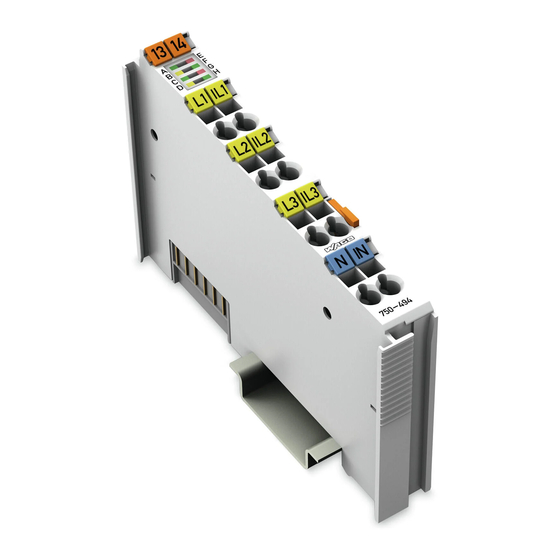
Figure 1: View Pos : 27 /Serie 750 ( WAGO-I/O-SYST EM)/Ger ätebesc hrei bung/Ansic ht/Ansic ht C ageCl amp® _Leg ende mit LED s_ohne Leis tungs kontakte @ 16\mod_1371816091053_21.doc x @ 124052 @ @ 1 Table 5: Legend for Figure “View”... -
Page 17: Connectors
Pos : 31.3 /Serie 750 (WAGO-I/O-SYST EM)/Wic htige Erläuterungen/Sicherheits- und sonstig e Hinweis e/Achtung/Achtung: ESD - Auf g ute Erdung der U mgebung ac hten! @ 7\mod_1266318538667_21.doc x @ 50708 @ @ 1 Ensure that the environment is well grounded! The devices are equipped with electronic components that may be destroyed by electrostatic discharge. -
Page 18: Cage Clamp
WAGO-I/O-SYSTEM 750 750-494 3-Phase Power Measurement Module Pos : 35 /Serie 750 ( WAGO-I/O-SYST EM)/Ger ätebesc hrei bung/Ansc hl üss e/CAGE CLAMP- Anschl üss e - Ü berschrift 3 @ 6\mod_1256296337770_21.doc x @ 43674 @ 3 @ 1 ® 3.2.3... -
Page 19: Display Elements
Display Elements Pos : 39 /Serie 750 ( WAGO-I/O-SYST EM)/Ger ätebesc hrei bung/Anz eigeelemente/Anal ogei ngangs klemmen/Anz eigeel emente 750- 0494, - 0495 @ 16\mod_1371738731125_21.doc x @ 123880 @ @ 1 LED A indicates the operating status, LEDs B … H indicate possible errors. -
Page 20: Operating Elements
Pos : 41 /All e Seri en (Allgemei ne Module)/Ü berschriften/Ebene 2/Bedi enel emente - Ü bers chrift 2 @ 4\mod_1239191655456_21.doc x @ 30439 @ 2 @ 1 Operating Elements Pos : 42 /Serie 750 ( WAGO-I/O-SYST EM)/Ger ätebesc hrei bung/Bedienel emente/Bedi enel emente Bus kl emme 75x- xxxx nicht vorhanden @ 4\mod_1236322031125_21.doc x @ 28063 @ @ 1 The I/O module 750-494 has no operating elements. -
Page 21: Schematic Diagram
Pos : 44 /All e Seri en (Allgemei ne Module)/Ü berschriften/Ebene 2/Sc hematis ches Sc haltbild - Ü bersc hrift 2 @ 4\mod_1240984441312_21.doc x @ 31967 @ 2 @ 1 Schematic Diagram Pos : 45 /Serie 750 ( WAGO-I/O-SYST EM)/Ger ätebesc hrei bung/Schematisc he Sc haltbil der/Anal ogeing angs kl emmen/Sc hematisc hes Sc haltbild 750-0494 @ 14\mod_1363957453847_21.doc x @ 115823 @ @ 1 Figure 5: Schematic Diagram Manual Version 1.2.0... -
Page 22: Figure 6: Fe Spring Contact
Device Description WAGO-I/O-SYSTEM 750 750-494 3-Phase Power Measurement Module Function Earth FE! In order to get a function earth, the connectors N and IN are connected to the mounting rail via a 470 pF capacitor and a spring contact. If the rail is correctly connected to PE, the immunity to interference is increased. -
Page 23: Technical Data
Pos : 47 /All e Seri en (Allgemei ne Module)/Ü berschriften/Ebene 2/Tec hnische D aten - Ü bersc hrift 2 @ 3\mod_1232967587687_21.doc x @ 26924 @ 2 @ 1 Technical Data Pos : 48.1 /Serie 750 (WAGO-I/O-SYST EM)/Ger ätebesc hrei bung/T echnisc he Daten/Anal ogeing angs kl emmen/T ec hnis che D aten 750-0494 @ 13\mod_1354714530947_21.doc x @ 107410 @ 33333 @ 1 3.6.1 Dimensions and Weight Table 8: Technical Data ‒... -
Page 24: Measured Values
Device Description WAGO-I/O-SYSTEM 750 750-494 3-Phase Power Measurement Module 3.6.4 Measured Values Table 11: Technical Data ‒ Measured Values Measuring procedure Calculation of true RMS for voltages and currents, sample rate 8 kHz synchronous on all 6 measuring inputs, 24 bits resolution... -
Page 25: Internal Bus Communication
Pos : 48.4 /Serie 750 (WAGO-I/O-SYST EM)/Ger ätebesc hrei bung/T echnisc he Daten/Ansc hluss tec hni k/T ec hnisc he D aten Verdr ahtungsebene CC - 0,08 bis 2,5mm2 @ 17\mod_1380121238809_21.doc x @ 132780 @ @ 1 Table 14: Technical Data – Field Wiring ®... -
Page 26: Climatic Environmental Conditions
Device Description WAGO-I/O-SYSTEM 750 750-494 3-Phase Power Measurement Module 3.6.7 Climatic Environmental Conditions Table 15: Technical Data – Climatic Environmental Conditions Operating temperature range 0 °C … 55 °C Operating temperature range for −20 °C … +60 °C components with extended... -
Page 27: Approvals
Pos : 51 /Serie 750 ( WAGO-I/O-SYST EM)/Ger ätebesc hrei bung/Z ulass ungen/Allgemei n/Z ulass ungen Bus kl emme 750- xxxx Allgemein, Standardversi on und all e Vari anten - Einl eitung @ 3\mod_1233911570312_21.doc x @ 27390 @ @ 1... -
Page 28: 3-Phase Power Measurement Module
Device Description WAGO-I/O-SYSTEM 750 750-494 3-Phase Power Measurement Module 750-494 750-494 /000-001 750-494 /025-000 750-494 /025-001 Pos : 61 /All e Seri en (Allgemei ne Module)/Z ulassungen/Sc hiffsz ul ass ungen/DN V GL (Det Nors ke Veritas Ger manisc her Ll oyd) Temp B, H um A, Vib B, EMC B, Enc A @ 29\mod_1488284111166_0.doc x @ 410521 @ @ 1... -
Page 29: Standards And Guidelines
Pos : 66 /Serie 750 ( WAGO-I/O-SYST EM)/Ger ätebesc hrei bung/N ormen und Ric htlini en/Nor men und Ric htlini en Bus kl emme 750-xxxx, Stanar dversion und alle Varianten - Ei nleitung @ 16\mod_1373883448625_21.doc... -
Page 30: Function Description
Pos : 73 /All e Seri en (Allgemei ne Module)/Ü berschriften/Ebene 1/Funkti onsbesc hrei bung - Ü bersc hrift 1 @ 4\mod_1239025975389_21.doc x @ 30003 @ 1 @ 1 Function Description Pos : 74 /Serie 750 ( WAGO-I/O-SYST EM)/F unktions beschr eibung/Funkti onsbesc hrei bung 750-0494 - Mes sprinzip, Mess werte @ 14\mod_1363085168365_21.doc x @ 114260 @ 222 @ 1 Measuring Principle The 3-phase power measurement module operates using 6 analog/digital converters for acquiring the current and voltage levels in all three phases. - Page 31 WAGO-I/O-SYSTEM 750 Function Description 750-494 3-Phase Power Measurement Module • Active energy acquisition total • Active energy delivery total • Reactive energy Lx • Reactive energy inductive Lx • Reactive energy capacitive Lx • Reactive energy total • Reactive energy inductive total •...
-
Page 32: Description Of Measured Values
Alternatively, the following DC measured values are available if DC measurement has been activated in the I/O module. See section "Commissioning" > "Configuration with WAGO-I/O-CHECK". DC measurements only possible in 2 measuring channels! DC measurements are only possible in the measuring channels L1-IL1 and L2-... -
Page 33: Figure 7: Rms Value Calculation (Example, Not To Scale)
RMS values. You can set the time period during which the mean value is to be generated using WAGO-I/O-CHECK, or parameters 34, 35, 36. The RMS minimum and maximum values for current and voltage are also determined over a configurable time period (WAGO-I/O-CHECK or parameters 37, 38, 39). -
Page 34: Figure 8: Allocation Of Active And Reactive Energy In The 4 Quadrants
Active power minimum and maximum values are determined over a configurable time period (WAGO-I/O-CHECK or parameters 37, 38, 39). In real supply networks, not all electrical loads are purely ohmic. Phase shifting occurs between current and voltage. However, this does not affect the method for determining the RMS values for current voltage previously described. - Page 35 The representation of the energy values can be scaled using a defined factor in the process image (PI). This factor can be set by the user with WAGO-I/O-CHECK or register 35 and can be changed at any time. The two examples below illustrate the...
- Page 36 Function Description WAGO-I/O-SYSTEM 750 750-494 3-Phase Power Measurement Module Harmonics Analysis The I/O module calculates the frequency spectrum for the periodic input signals and analyzes the fundamental component and the next 40 harmonics for each phase. This analysis can be conducted on one of the three phases (L1 or L2 or L3).
-
Page 37: Figure 9: 4-Quadrant Display For Active And Reactive Power
The 4-quadrant display appears as follows: Figure 9: 4-Quadrant Display for Active and Reactive Power The 4-quadrant display is also shown in WAGO- I/O-CHECK for the measured value views "Overview", "Phase Lx" and "Power" in the dialog "3-phase power measurement". -
Page 38: Measuring Errors And Accuracy
23-31). Signaling is carried out in the process image (PI). Pos : 75 /Serie 750 ( WAGO-I/O-SYST EM)/F unktions beschr eibung/Funkti onsbesc hrei bung 750-0494 - Mes sfehl er und M essgenauig kei t @ 24\mod_1446714888787_21.doc x @ 194992 @ 2 @ 1 Measuring Errors and Accuracy The measuring errors of the I/O module are specified in the table below. -
Page 39: Figure 10: Input Overdrive (Clipping)
WAGO-I/O-SYSTEM 750 Function Description 750-494 3-Phase Power Measurement Module frequency and current are no longer possible. The measuring accuracy of all current-depending variables (current, power, energy) falls off by 0.4%. Near the ZC limit, the accuracy of the phase angle measurement decreases to a value of ±... -
Page 40: Process Image
Process Image Pos : 78 /Serie 750 ( WAGO-I/O-SYST EM)/Proz ess abbild Kl emmenbus /Analogei ngangs klemmen/Pr ozessabbild 750- 0494 @ 14\mod_1362749555043_21.doc x @ 114070 @ 2233233232333332 @ 1 The I/O module provides, on 1 logical channel, 24 bytes input and 24 bytes output process data to a fieldbus coupler/controller. -
Page 41: Output Data
WAGO-I/O-SYSTEM 750 Process Image 750-494 3-Phase Power Measurement Module Output Data The output data is transmitted to the I/O module by the fieldbus coupler/controller. This data consists of 4 control words and 8 data words. 5.2.1 Definition of Control Words... -
Page 42: Definition Of Output Data Words
Process Image WAGO-I/O-SYSTEM 750 750-494 3-Phase Power Measurement Module Expanded control word 2 Byte 4 (Bit 7) (Bit 6) (Bit 5) (Bit 4) (Bit 3) (Bit 2) (Bit 1) (Bit 0) MET_ID_1 MET_ID_1 ID for selection of the measured value from the collection COL_ID, which is delivered with process value 1 of the input data. -
Page 43: Input Data
WAGO-I/O-SYSTEM 750 Process Image 750-494 3-Phase Power Measurement Module Input Data The input data are transmitted to the fieldbus coupler/controller by the I/O module. This data consists of 4 status words and 8 data words (process values 1 … 4). -
Page 44: 3-Phase Power Measurement Module
Process Image WAGO-I/O-SYSTEM 750 750-494 3-Phase Power Measurement Module OVER_2 Range limiting for process value 2: 0 = Ok 1 = The measured value shown in process value 2 is situated outside the defined value range. OVER_3 Range limiting for process value 3:... - Page 45 WAGO-I/O-SYSTEM 750 Process Image 750-494 3-Phase Power Measurement Module STAT4 STAT_SEL = Status Lx = L1 / L2 / L3: - Status Zero crossings: 0 = Signal zero crossings at the phase Lx 1 = No signal zero crossings at the phase Lx...
-
Page 46: Definition Of Input Data Words
Process Image WAGO-I/O-SYSTEM 750 750-494 3-Phase Power Measurement Module Expanded status word 2 Byte 4 (Bit 7) (Bit 6) (Bit 5) (Bit 4) (Bit 3) (Bit 2) (Bit 1) (Bit 0) MET_ID_1_SEL MET_ID_1_SEL ID for the measured value from the collection COL_ID_SEL which is in process value 1 of the input data. - Page 47 WAGO-I/O-SYSTEM 750 Process Image 750-494 3-Phase Power Measurement Module Byte 10 (Bit 7) (Bit 6) (Bit 5) (Bit 4) (Bit 3) (Bit 2) (Bit 1) (Bit 0) PROC1[23:16] PROC1[23:16] => See Process value 1 – Byte 8 Byte 11 (Bit 7)
- Page 48 Process Image WAGO-I/O-SYSTEM 750 750-494 3-Phase Power Measurement Module Byte 17 (Bit 7) (Bit 6) (Bit 5) (Bit 4) (Bit 3) (Bit 2) (Bit 1) (Bit 0) PROC3[15:8] PROC3[15:8] => See Process value 3 – Byte 16 Byte 18 (Bit 7)
-
Page 49: Process Image Descriptions
WAGO-I/O-SYSTEM 750 Process Image 750-494 3-Phase Power Measurement Module Process Image Descriptions The I/O module provides a large number of measured values for a three-phase supply network. These measured values are organized into collections which can be selected by specifying the COL_ID. The following collections are available: COL_ID = 007 –... -
Page 50: 3-Phase Power Measurement Module
Process Image WAGO-I/O-SYSTEM 750 750-494 3-Phase Power Measurement Module The I/O module measured values are made available in the process image as a function of the selected collection (COL_ID) and of the measured values selected in the collection. Collections DC (007) and AC measured values (009) The collection is selected in the I/O module output data and the various measured values selected from the collection using the corresponding MET_IDs. - Page 51 WAGO-I/O-SYSTEM 750 Process Image 750-494 3-Phase Power Measurement Module Example 2: Byte Output data Input data 0x00 0x44 0x02 (Status query) 0x02 0x00 0x40 0x09 (COL_ID) 0x09 (COL_ID_SEL) 0x06 (MET_ID_1) 0x06 (MET_ID_1_SEL) 0x03 (MET_ID_2) 0x03 (MET_ID_2_SEL) 0x4E (MET_ID_3) 0x4E (MET_ID_3_SEL)
- Page 52 Process Image WAGO-I/O-SYSTEM 750 750-494 3-Phase Power Measurement Module Collections for harmonics analysis (020, 021, 022) The corresponding harmonics analysis collection is selected in the I/O module output data and the MET_IDs set. These measured values are then made available in the input data.
- Page 53 WAGO-I/O-SYSTEM 750 Process Image 750-494 3-Phase Power Measurement Module Ueff – 1st harmonic L1 [15:8] Ueff – 1st harmonic L1 [23:16] Ueff – 1st harmonic L1 [31:24] Ueff – 2nd harmonic L1 [7:0] Ueff – 2nd harmonic L1 [15:8] Ueff – 2nd harmonic L1 [23:16] Ueff –...
-
Page 54: Building-Up The Measured Values
Process Image WAGO-I/O-SYSTEM 750 750-494 3-Phase Power Measurement Module The status query was also set in the examples given here. In example 1, the status query is made for the I/O module. The status word (Byte 0) is at 0x48, an error occurred at the I/O module (ERROR, ERR_BK). -
Page 55: Collections Of Measured Values
WAGO-I/O-SYSTEM 750 Process Image 750-494 3-Phase Power Measurement Module Collections of Measured Values 5.5.1 Collection 007 – DC Measured Values Wait to the end of build-up time! The selected measured values of the collection are stable after approx. 1400 ms! -
Page 56: Table 18: Measured Values Of Collection 009 In The Process Image (Pi)
Process Image WAGO-I/O-SYSTEM 750 750-494 3-Phase Power Measurement Module Table 18: Measured Values of Collection 009 in the Process Image (PI) Data Scaling Factor PI Update MET_ID Measured Value Type Rate PI [ms] Variants Variants Voltage RMS voltage L1-N UInt32 0.01V... - Page 57 0.05VA Apparent power L2 UInt32 0.01VA 0.05VA Apparent power L3 UInt32 0.01VA 0.05VA Energy Setup with WAGO-I/O- Active energy L1 Int32 CHECK or in Register 35 Setup with WAGO-I/O- CHECK Active energy L2 Int32 or in Register 35 Setup with WAGO-I/O-...
- Page 58 Process Image WAGO-I/O-SYSTEM 750 750-494 3-Phase Power Measurement Module CHECK or in Register 35 Setup with WAGO-I/O- CHECK Reactive energy L1 Int32 or in Register 35 Setup with WAGO-I/O- Reactive energy L2 Int32 CHECK or in Register 35 Setup with WAGO-I/O-...
- Page 59 WAGO-I/O-SYSTEM 750 Process Image 750-494 3-Phase Power Measurement Module Frequency Supply network frequency L1 UInt32 0.001Hz 0.001Hz Supply network frequency L2 UInt32 0.001Hz 0.001Hz Supply network frequency L3 UInt32 0.001Hz 0.001Hz Max. supply network frequency UInt32 0.001Hz 0.001Hz Max. supply network frequency UInt32 0.001Hz...
-
Page 60: Collection 020 - Harmonics Analysis L1
Process Image WAGO-I/O-SYSTEM 750 750-494 3-Phase Power Measurement Module 5.5.3 Collection 020 – Harmonics Analysis L1 Wait to the end of build-up time! The selected measured values of the collection are stable after approx. 1100 ms! When switching to another harmonic (1 … 40) a build-up time of 1100 ms must be... -
Page 61: Collection 021 - Harmonics Analysis L2
WAGO-I/O-SYSTEM 750 Process Image 750-494 3-Phase Power Measurement Module 5.5.4 Collection 021 – Harmonics Analysis L2 Wait to the end of build-up time! The selected measured values of the collection are stable after approx. 1100 ms! When switching to another harmonic (1 … 40) a build-up time of 1100 ms must... -
Page 62: Collection 022 - Harmonics Analysis L3
Process Image WAGO-I/O-SYSTEM 750 750-494 3-Phase Power Measurement Module 5.5.5 Collection 022 – Harmonics Analysis L3 Wait to the end of build-up time! The selected measured values of the collection are stable after approx. 1100 ms! When switching to another harmonic (1 … 40) a build-up time of 1100 ms must... -
Page 63: Examples Of Calculating The Measured Values From The Process Values
WAGO-I/O-SYSTEM 750 Process Image 750-494 3-Phase Power Measurement Module Examples of Calculating the Measured Values from the process values The format of the measured values with sign (Int16) is the two's complement. Generally, use the following equation to calculate the measured values from the... -
Page 64: 3-Phase Power Measurement Module
(CTR) are 1:45 and 1:40. The I/O module allows you to set user scaling using WAGO-I/O-CHECK or via Register 32, bits 12, 13 and 14. If the bit is set to 0, user scaling is disabled and the transformation ratio of the current is 1:1. -
Page 65: Table 27: Register 35
WAGO-I/O-SYSTEM 750 Process Image 750-494 3-Phase Power Measurement Module A. User Scaling OFF, Measurement without Current Transformer Current 1A-varints 5A-variants Register 32, bits 12 … 14 Register 39 … 41 0x0001 (1) 0x0001 (1) (D-CTR) Process value 0x000010A9 (4250) 0x00002062 (8290) Scaling factor PI 0.0001A... - Page 66 Process Image WAGO-I/O-SYSTEM 750 750-494 3-Phase Power Measurement Module Active Power 1A-varints 5A-variants Register 32, bits 12 … 14 Register 39 … 41 0x002D (45) 0x0028 (40) (D-CTR) Process value 0x000049B5 (18869) 0x0001C3F8 (115704) Scaling factor PI 0.01W 0.05W Equation...
-
Page 67: Mounting
I/O modules with fewer power contacts. Pos : 81.2 /Serie 750 (WAGO-I/O-SYST EM)/Wic htige Erläuterungen/Sicherheits- und sonstig e Hinweis e/Vorsic ht/Vorsicht: Verl etz ungsgefahr durc h s charfkantige M ess er kontakte! @ 6\mod_1256193279401_21.doc x @ 43414 @ @ 1 Risk of injury due to sharp-edged blade contacts! The blade contacts are sharp-edged. -
Page 68: Inserting And Removing Devices
WAGO-I/O-SYSTEM 750 750-494 3-Phase Power Measurement Module Pos : 81.6 /Serie 750 (WAGO-I/O-SYST EM)/M ontieren/D emontieren/Geräte einfüg en und entfer nen - Ü berschrift 2 @ 3\mod_1231768483250_21.doc x @ 25950 @ 2 @ 1 Inserting and Removing Devices Pos : 81.7 /All e Seri en ( Allgemei ne Module)/Sicherheits- und s ons tige Hi nweis e/Ac htung/Achtung: Arbeiten an Ger äten nur s pannungsfr ei durc hführ en! @ 6\mod_1256193963573_21.doc x @ 43426 @ @ 1 Perform work on devices only if they are de-energized! Working on energized devices can damage them. -
Page 69: Removing The I/O Module
WAGO-I/O-SYSTEM 750 Mounting 750-494 3-Phase Power Measurement Module Pos : 81.10 /Serie 750 ( WAGO-I/O-SYST EM)/Monti eren/D emonti eren/Bus kl emme entfer nen @ 4\mod_1239169375203_21.doc x @ 30334 @ 3 @ 1 6.2.2 Removing the I/O Module Remove the I/O module from the assembly by pulling the release tab. -
Page 70: Connect Devices
Connect Devices Pos : 84 /Serie 750 ( WAGO-I/O-SYST EM)/Ans chli eßen/Leiter an C AGE C LAM P ans chli eßen ( allgemei n) - Übersc hrift 2 und Text @ 3\mod_1225448660171_21.doc x @ 24928 @ 2 @ 1 ®... -
Page 71: Voltage Measurement
Voltage Measurement Pos : 87 /Serie 750 ( WAGO-I/O-SYST EM)/Ans chli eßen/Anschl uss beispi ele/Anal ogei ngangs kl emmen/Spannungsmess ung 750-0493, - 0494 @ 16\mod_1372770254968_21.doc x @ 125343 @ @ 1 In order to measure just the 3 phase voltages of a supply network, connect its 4 ®... -
Page 72: Current Measurement
Pos : 89 /All e Seri en (Allgemei ne Module)/Ü berschriften/Ebene 2/Str ommes sung - Ü bersc hrift 2 @ 13\mod_1346248472189_21.doc x @ 102101 @ 2 @ 1 Current Measurement Pos : 90 /Serie 750 ( WAGO-I/O-SYST EM)/Ans chli eßen/Anschl uss beispi ele/Anal ogei ngangs kl emmen/Str ommess ung 750-0494 @ 16\mod_1372769492854_21.doc x @ 125335 @ 3344443 @ 1 7.3.1... -
Page 73: Current Transformers
WAGO-I/O-SYSTEM 750 Connect Devices 750-494 3-Phase Power Measurement Module 7.3.2 Current Transformers For measuring currents greater than 1 A resp. 5 A you have to use external current transformers. Normally, the selection of the current transformers is not a critical factor. The... -
Page 74: Protection Against Shock Hazard Voltages
Connect Devices WAGO-I/O-SYSTEM 750 750-494 3-Phase Power Measurement Module connected measuring instruments. FS shall be max. 10 for the 1 A module resp. max. 5 for the 5 A module. Note the max. continuous measuring current of 1 A resp. 5 A! The max. -
Page 75: Additional Measuring Instruments In The Current Path
WAGO-I/O-SYSTEM 750 Connect Devices 750-494 3-Phase Power Measurement Module 7.3.3 Additional Measuring Instruments in the Current Path Please note that adding measuring instruments (such as ammeters) in the current path can substantially increase the total apparent power. ® In addition, the CAGE CLAMP IN of the I/O module must form a star point (neutral) for the three secondary windings. -
Page 76: Power Measurement
Pos : 92 /All e Seri en (Allgemei ne Module)/Ü berschriften/Ebene 2/Leistungs mess ung - Ü berschrift 2 @ 13\mod_1346327054898_21.doc x @ 102149 @ 2 @ 1 Power Measurement Pos : 93 /Serie 750 ( WAGO-I/O-SYST EM)/Ans chli eßen/Anschl uss beispi ele/Anal ogei ngangs kl emmen/Leistungs mess ung 750-0494 @ 16\mod_1372770633216_21.doc x @ 125347 @ 33 @ 1 7.4.1 Power Measurement on a Machine ®... -
Page 77: Figure 18: Power Measurement On Two Motors Regulated By Frequency Converters
WAGO-I/O-SYSTEM 750 Connect Devices 750-494 3-Phase Power Measurement Module Figure 18: Power Measurement on Two Motors Regulated by Frequency Converters The galvanic separation achieved by the 3-phase transformer (Yy0) allows measurement after the frequency converter. ® CAGE CLAMP N must be connected to earth! Based on the galvanic separation by the 3-phase transformer, you must ground ®... - Page 78 Connect Devices WAGO-I/O-SYSTEM 750 750-494 3-Phase Power Measurement Module Measurement of DC voltage/current (such as holding current for synchronous motors) is not possible with this configuration. Practical results will be yielded for frequencies greater than 5 Hz, depending on the 3-phase transformer and current transformers that are used.
-
Page 79: Commissioning
Commissioning Pos : 96 /Serie 750 ( WAGO-I/O-SYST EM)/In Betrieb nehmen/Parametrier en mit WAGO- I/O-CH ECK/Parametrier en mit WAGO-I/O-CH ECK 750-0494 @ 15\mod_1367496874664_21.doc x @ 118340 @ 233333 @ 1 The I/O module latched in the bus node and wired for the measurement can be put into operation using the WAGO-I/O-CHECK software for Windows. -
Page 80: Configuration With Wago-I/O-Check
Configuration with WAGO-I/O-CHECK Right-click on the image of the I/O module and select the [Settings] menu item. See the figure below: Figure 19: WAGO-I/O-CHECK User Interface, Bus Node With I/O Module 750-494 The "3-Phase Power Measurement" dialog opens. See figure below. Manual... -
Page 81: Figure 20: „3-Phase Power Measurement" Dialog
[Calibration] Opens the calibration dialog. More information is available from the WAGO Support. The buttons for the individual measured value views appear in the menu (2). The status bar (3) displays the connection icon and IP address of the fieldbus coupler/controller or the name of the COM port. -
Page 82: Figure 21: „Settings" Dialog
Commissioning WAGO-I/O-SYSTEM 750 750-494 3-Phase Power Measurement Module Figure 21: „Settings“ Dialog The main menu (1) with the Application, Phase L1, Phase L2, Phase L3, I/O Module, Energy and Factory Settings tabs are on the left side. These are explained in more detail in the following sections. -
Page 83: Application" Tab
=milli or 10 =1 or 10 =kilo. In addition, you specify the storage path for the measured value records. See "Measurement Recording" in the following section "Displaying the Measured Values via WAGO-I/O-CHECK". Figure 22: „Application“ Tab Manual Version 1.2.0... -
Page 84: Phase L1", "Phase L2", "Phase L3" Tabs
Commissioning WAGO-I/O-SYSTEM 750 750-494 3-Phase Power Measurement Module 8.1.2 "Phase L1”, “Phase L2”, “Phase L3” Tabs Use the "Phase L1", "Phase L2", "Phase L3" tabs to configure user scaling, min.- /max. values and general parameters. These settings are saved to the I/O module. -
Page 85: I/O Module" Tab
WAGO-I/O-SYSTEM 750 Commissioning 750-494 3-Phase Power Measurement Module For „Min.-/Max. values“ specify the thresholds for undervoltage, overvoltage and overcurrent. Under- resp. overshooting one of these values results in setting an error bit in the status byte of the process image and activating a red error LED. -
Page 86: Figure 24: „I/O Module" Tab
Commissioning WAGO-I/O-SYSTEM 750 750-494 3-Phase Power Measurement Module Figure 24: „I/O Module“ Tab Manual Version 1.2.0... -
Page 87: Energy" Tab
After entering a password, you can set or reset the energy values per phase on the "Energy" tab. The initial password is: wago. Please change this password on first use by clicking [Change password]. Should you have forgotten the password deinstall and install again the application “3-Pase Power Measurement”. -
Page 88: Factory Settings" Tab
Commissioning WAGO-I/O-SYSTEM 750 750-494 3-Phase Power Measurement Module 8.1.5 "Factory Settings" Tab After entering a password (see "Energy" tab above), you can reset all parameters of the I/O module to their factory settings on the "Factory Settings" tab. List of factory settings A list of factory settings may be found in section “Appendix”. -
Page 89: Displaying The Measured Values Via Wago-I/O-Check
Pos : 97 /D okumentation allgemei n/Glieder ungs elemente/---Seitenwechs el--- @ 3\mod_1221108045078_0.doc x @ 21810 @ @ 1 Pos : 98 /All e Seri en (Allgemei ne Module)/Ü berschriften/Ebene 2/Anzeig en der M ess wer te mi t WAGO-I/O-CH ECK - Übersc hrift 2 @ 13\mod_1355494395030_21.doc x @ 107680 @ 2 @ 1... -
Page 90: Figure 27: Measured Values - Overview
Change of the Measuring Units! Specify the prefixes of the measuring units by selecting Home > Settings > Application. See section "Configuration with WAGO-I/O-CHECK" > "Application" Tab. The units can only be changed in the lists with the same physical variables. For lists with different variables, base units are always used! Figure 27: Measured Values ‒... -
Page 91: Figure 28: Measured Values - Phases
Note: Peak values are only displayed if this phase was selected for peak value measurement. See section "Configuration with WAGO-I/O-CHECK" > "I/O module" Tab. Overcurrent, under and overvoltage are identified as a red square, if not present as a green one. -
Page 92: Figure 29: Measured Values - Currents And Voltages
Note: Peak values are only displayed for the phase which was selected for peak value measurement. See section "Configuration with WAGO-I/O-CHECK" > "I/O module" Tab. Overcurrent, under and overvoltage are identified as a red square, if not present as a green one. -
Page 93: Figure 30: Measured Values - Power
WAGO-I/O-SYSTEM 750 Commissioning 750-494 3-Phase Power Measurement Module If you select Power, you see active, reactive and apparent power of all 3 phases with min. and max. values, the power factors and the 4-quadrant displays. • Active power • Reactive power •... -
Page 94: Figure 31: Measured Values - Energies
Commissioning WAGO-I/O-SYSTEM 750 750-494 3-Phase Power Measurement Module If you select Energies, you see the active energies with supply and delivery, reactive energies with capacitive and inductive component and the apparent energies that have been consumed/generated since the beginning of the measurement. -
Page 95: Figure 32: Measured Values - Dc
WAGO-I/O-SYSTEM 750 Commissioning 750-494 3-Phase Power Measurement Module Selecting DC Measurements, you can see the measured DC components of the measuring signals, i.e. current, voltage and power. Select DC mode on the "I/O Module" tab. The AC variables are then not measured or displayed. -
Page 96: Figure 33: Measured Values - Harmonics Chart
Commissioning WAGO-I/O-SYSTEM 750 750-494 3-Phase Power Measurement Module If you select Harmonics you get a chart or a table regarding the 40 harmonics of the phases. The tab „Harmonics analysis“ opens. Here you select chart or table view, the phase to be analyzed and the measured value (voltage or current). -
Page 97: Figure 34: Measured Values - Harmonics Table
WAGO-I/O-SYSTEM 750 Commissioning 750-494 3-Phase Power Measurement Module The Table View shows the following values of 1st harmonic (fundamental wave) and another 3 selectable harmonics of the selected phase: • Current • Harmonic distortion THD and HD current • Voltage •... -
Page 98: Figure 35: Measured Values - Recording
Commissioning WAGO-I/O-SYSTEM 750 750-494 3-Phase Power Measurement Module On the Measurement Recording view, 3 measured variables are represented in chronological sequence. You can select the measured variables you want to see in the 3 drop-down lists. Figure 35: Measured Values ‒ Recording In general, you can select in the 3 waveforms whether: •... -
Page 99: Diagnostics
Pos : 101 /Alle Serien (Allgemei ne M odul e)/Ü bersc hriften/Ebene 1/Di agnose - Übersc hrift 1 @ 4\mod_1240831069471_21.doc x @ 31372 @ 1 @ 1 Diagnostics Pos : 102 /Serie 750 (WAGO-I/O-SYST EM)/Diagnos e/Bus klemmen/Diagnos e 750- 0494, - 0495 @ 13\mod_1348662372924_21.doc x @ 103550 @ @ 1 LED A indicates the operating status, LEDs B … H indicate possible errors. -
Page 100: Appendix
Pos : 104 /Alle Serien (Allgemei ne M odul e)/Ü bersc hriften/Ebene 1/Anhang - Ü berschrift 1 @ 4\mod_1239874070437_21.doc x @ 30560 @ 1 @ 1 Appendix Pos : 105 /Serie 750 (WAGO-I/O-SYST EM)/Anhang/Beis piel e für C SV-Datei en 750-494 @ 15\mod_1365497815779_21.doc x @ 116814 @ 233 @ 1 10.1 Examples of CSV Data Files 10.1.1... - Page 101 WAGO-I/O-SYSTEM 750 Appendix 750-494 3-Phase Power Measurement Module Power Factor PF L2 Power Factor PF L3 0.67 Quadrant L1 Quadrant L2 Quadrant L3 Average Value Current (eff.) L1 0.4213 A Average Value Current (eff.) L2 0.4912 A Average Value Current (eff.) L3 0.4937 A...
- Page 102 Appendix WAGO-I/O-SYSTEM 750 750-494 3-Phase Power Measurement Module Active Energy Delivery L3 0 Wh Reactive Energy L1 0 varh Reactive Energy L2 -30 varh Reactive Energy L3 0 varh Reactive Energy Capacitive L1 0 varh Reactive Energy Capacitive L2 30 varh...
- Page 103 WAGO-I/O-SYSTEM 750 Appendix 750-494 3-Phase Power Measurement Module Overcurrent threshold value 1000 A Interval observation : arithm. mean calculation 60 s Interval observation : peak value measurement 10 Half-Wave(s) Heed transformer ratio True Automatic reset of the min./max. values True...
-
Page 104: Csv Data File „Measurement Recording
Appendix WAGO-I/O-SYSTEM 750 750-494 3-Phase Power Measurement Module 10.1.2 CSV Data File „Measurement Recording“ The following table shows an example CSV data file generated in the view „Measurement Recording“ with [Start]. In this example the variable „Voltage (eff.) L1-N“ was selected shown as measuring series with 20 values. -
Page 105: Factory Settings
Pos : 107 /Alle Serien (Allgemei ne M odul e)/Ü bersc hriften/Ebene 2/Wer ksei nstellungen - Ü berschrift 2 @ 15\mod_1366373603819_21.doc x @ 117430 @ 2 @ 1 10.2 Factory Settings Pos : 108 /Serie 750 (WAGO-I/O-SYST EM)/Anhang/Wer ks einstellungen (Default) 750-494 @ 15\mod_1367219920706_21.doc x @ 118160 @ @ 1 The following values are stored in registers and parameters at delivery: Table 23: Factory Settings R32 ≙... -
Page 106: 3-Phase Power Measurement Module
Appendix WAGO-I/O-SYSTEM 750 0x02FAF080 ≙ 5 000 A 750-494 3-Phase Power Measurement Module 0x02FAF080 ≙ 5 000 A P28, P29 0x0004 ≙ 60 s P30, P31 0x0004 ≙ 60 s 0x0004 ≙ 60 s 0x000A ≙ 2 s 0x000A ≙ 2 s 0x000A ≙... -
Page 107: Register Assignment
WAGO-I/O-SYSTEM 750 Appendix 750-494 3-Phase Power Measurement Module Pos : 110 /Serie 750 (WAGO-I/O-SYST EM)/In Betri eb nehmen/Par ametrieren über R egister kommuni kati on/Registerbeleg ung und Parameterbel. 750-494 @ 15\mod_1364991593084_21.doc x @ 116384 @ 22 @ 1 10.3 Register Assignment The tables below show the assignments and factory settings for the registers written during configuration and during operation. -
Page 108: Table 25: Register 5
Appendix WAGO-I/O-SYSTEM 750 750-494 3-Phase Power Measurement Module Table 25: Register 5 Register 5 – Command interface response Function Data type Access Factory setting Command Interface Response UINT 0x0000 High byte Sequence number (Session ID) Low byte Response Request A mirror image of the request command is created when the command is successfully applied. -
Page 109: Table 28: Register 36
WAGO-I/O-SYSTEM 750 Appendix 750-494 3-Phase Power Measurement Module Automatic deleting of minimum and maximum current, voltage and power values is activated. Bit 11: -Reserved- Bit 12: User-defined scaling (current transformer ratio) phase L1 User-defined scaling is deactivated, the transformation ratio is 1:1 (factory setting). -
Page 110: Table 30: Register 38
Appendix WAGO-I/O-SYSTEM 750 750-494 3-Phase Power Measurement Module Table 30: Register 38 Register 38 – Undervoltage threshold phase L3 Function Data type Access Factory setting Undervoltage threshold phase L3, UINT 0 x 0000, 0 V Resolution: 0.1 V Checking of undervoltage threshold is deactivated. -
Page 111: Table 34: Register 43
WAGO-I/O-SYSTEM 750 Appendix 750-494 3-Phase Power Measurement Module Table 34: Register 43 Register 43 – Observation interval, peak value measurement phase L1 Function Data type Access Factory setting Observation interval, peak value measurement, UINT 0 x 000 A phase L1 0 …... -
Page 112: Table 38: Register 47
Appendix WAGO-I/O-SYSTEM 750 750-494 3-Phase Power Measurement Module Table 38: Register 47 Register 47 – Error register for the parameter channel Function Data type Access Factory setting Error register for the parameter channel UINT 0x0000 Calibration procedure, no error Calibration procedure, division by zero Calibration procedure "Gain"... -
Page 113: Parameter Assignment
WAGO-I/O-SYSTEM 750 Appendix 750-494 3-Phase Power Measurement Module Table 44: Register 53 Register 53 – Container 6 Function Data type Access Factory setting Container 6, UINT 0x0000 for energy preset and calibration Table 45: Register 54 Register 54 – Container 7... - Page 114 Appendix WAGO-I/O-SYSTEM 750 750-494 3-Phase Power Measurement Module Table 50: Parameter 13 Parameter 13 – Undervoltage threshold phase L2 Function Data type Access Factory setting -Corresponds to register 37. (See section above.) Table 51: Parameter 14 Parameter 14 – Undervoltage threshold phase L3...
- Page 115 WAGO-I/O-SYSTEM 750 Appendix 750-494 3-Phase Power Measurement Module Table 58: Parameter 22 Parameter 22 – Storing interval for energy values Function Data type Access Factory setting -Corresponds to register 46. (See section above.) Table 59: Parameter 23 Parameter 23 – Overvoltage threshold phase L1...
- Page 116 Appendix WAGO-I/O-SYSTEM 750 750-494 3-Phase Power Measurement Module Table 64: Parameter 30 and 31 Parameter 30 und 31 – Overcurrent threshold phase L3 Function Data type Access Factory setting Overcurrent threshold phase L3, UINT 0x02FAF080 Resolution: 0.1 mA (5 000 A) Overcurrent is not checked.
- Page 117 WAGO-I/O-SYSTEM 750 Appendix 750-494 3-Phase Power Measurement Module Table 67: Parameter 36 Parameter 36 – Calculation interval arithmetic mean values phase L3 Function Data type Access Factory setting Calculation interval arithmetic mean values UINT 0x0004 phase L3 10 s 15 s...
- Page 118 Appendix WAGO-I/O-SYSTEM 750 750-494 3-Phase Power Measurement Module Table 71: Parameter 40 Parameter 40 – Factor NOLOAD-threshold active energy Function Data type Access Factory setting Factor NOLOAD-threshold active energy UINT 0x0000 (disabled) The NOLOAD-threshold is disabled. 1 … 19: -reserved- 20 …...
-
Page 119: Use In Hazardous Environments
Pos : 112.1 /Alle Serien (Allgemeine M odul e)/Übersc hriften/Ebene 1/Eins atz in explosionsgefährdeten Bereic hen - Übersc hrift 1 @ 3\mod_1224075191281_21.doc x @ 24084 @ 1 @ 1 Use in Hazardous Environments Pos : 112.2 /Serie 750 ( WAGO-I/O-SYST EM)/Ei ns atz i n Ex-Bereic hen/Einsatzbereic h Serie 750 @ 3\mod_1234272230203_21.doc x @ 27500 @ @ 1 The WAGO-I/O-SYSTEM 750 (electrical equipment) is designed for use in Zone 2 hazardous areas. -
Page 120: Marking Configuration Examples
Pos : 112.6 /Serie 750 ( WAGO-I/O-SYST EM)/Ei ns atz i n Ex-Bereic hen/Beispi elbedruc kung der ATEX- und IEC-Ex-z ugel ass enen Bus kl emmen g emäß CEN ELEC und IEC _2013 @ 14\mod_1360569228625_21.doc... - Page 121 WAGO-I/O-SYSTEM 750 Use in Hazardous Environments 750-494 3-Phase Power Measurement Module Table 74: Description of Marking Example for Approved I/O Modules According to ATEX and IECEx Marking Description TÜV 07 ATEX 554086 X Approving authority and certificate numbers IECEx TUN 09.0001 X...
-
Page 122: Figure 38: Side Marking Example For Approved Ex I I/O Modules
750-494 3-Phase Power Measurement Module Pos : 112.8 /Serie 750 ( WAGO-I/O-SYST EM)/Ei ns atz i n Ex-Bereic hen/Beispi elbedruc kung der Ex-i- und IEC- Ex-i-zugel ass enen Bus kl emmen gemäß CEN ELEC und IEC_2013 @ 14\mod_1360569320118_21.doc x @ 111298 @ @ 1 Figure 38: Side Marking Example for Approved Ex i I/O Modules According to ATEX and IECEx. - Page 123 WAGO-I/O-SYSTEM 750 Use in Hazardous Environments 750-494 3-Phase Power Measurement Module Table 75: Description of Marking Example for Approved Ex i I/O Modules According to ATEX and IECEx Marking Description TÜV 07 ATEX 554086 X Approving authority and certificate numbers IECEx TUN 09.0001X...
- Page 124 Use in Hazardous Environments WAGO-I/O-SYSTEM 750 750-494 3-Phase Power Measurement Module Table 75: Description of Marking Example for Approved Ex i I/O Modules According to ATEX and IECEx Gases Equipment group: All except mining 3(1)G Category 3 (Zone 2) equipment containing a safety...
-
Page 125: Marking For America According To Nec 500
Marking for America According to NEC 500 Pos : 112.11 /Seri e 750 ( WAGO-I/O-SYSTEM)/Einsatz in Ex- Ber eichen/Beis piel bedr uc kung gemäß N EC 500_2013 @ 14\mod_1360580302684_21.doc x @ 111353 @ @ 1 Figure 40: Side Marking Example for I/O Modules According to NEC 500 Figure 41: Text Detail –... -
Page 126: Installation Regulations
Special Notes Regarding Explosion Protection Pos : 112.16.2 /Seri e 750 ( WAGO-I/O-SYSTEM)/Eins atz in Ex- Ber eichen/Bes ondere Hinweise hi nsic htlic h Expl osionss chutz _2017 @ 29\mod_1491556994025_21.doc x @ 415448 @ @ 1 The following warning notices are to be posted in the immediately proximity of the WAGO-I/O-SYSTEM 750 (hereinafter “product”):... - Page 127 WAGO-I/O-SYSTEM 750 Use in Hazardous Environments 750-494 3-Phase Power Measurement Module Explosive atmosphere occurring simultaneously with assembly, installation or repair work must be ruled out. Among other things, these include the following activities • Insertion and removal of components •...
-
Page 128: Special Notes Regarding Ansi/Isa Ex
Special Notes Regarding ANSI/ISA Ex Pos : 112.16.5 /Seri e 750 ( WAGO-I/O-SYSTEM)/Eins atz in Ex- Ber eichen/ANSI/ISA gemäß UL File E198726_2017 @ 29\mod_1491557259544_21.doc x @ 415451 @ @ 1 For ANSI/ISA Ex acc. to UL File E198726, the following additional requirements apply: •... -
Page 129: List Of Figures
Figure 17: Power Measurement on a Machine ............76 Figure 18: Power Measurement on Two Motors Regulated by Frequency Converters ....................77 Figure 19: WAGO-I/O-CHECK User Interface, Bus Node With I/O Module 750-494 ......................80 Figure 20: „3-Phase Power Measurement“ Dialog ..........81 Figure 21: „Settings“... - Page 130 List of Figures WAGO-I/O-SYSTEM 750 750-494 3-Phase Power Measurement Module Figure 41: Text Detail – Marking Example for Approved I/O Modules According to NEC 500................125 Pos : 115 /Dokumentati on allgemei n/Gli ederungsel emente/---Seitenwec hs el--- @ 3\mod_1221108045078_0.doc x @ 21810 @ @ 1 Manual Version 1.2.0...
-
Page 131: List Of Tables
WAGO-I/O-SYSTEM 750 List of Tables 750-494 3-Phase Power Measurement Module Pos : 116 /Dokumentati on allgemei n/Verz eichniss e/T abellenverzeic hnis - Ü bers chrift oG und Verzeic hnis @ 3\mod_1219222958703_21.doc x @ 21084 @ @ 1 List of Tables Table 1: Variants ..................... - Page 132 List of Tables WAGO-I/O-SYSTEM 750 750-494 3-Phase Power Measurement Module Table 49: Parameter 12 ..................113 Table 50: Parameter 13 ..................114 Table 51: Parameter 14 ..................114 Table 52: Parameter 15 ..................114 Table 53: Parameter 16 ..................114 Table 54: Parameter 17 ..................
- Page 133 WAGO-I/O-SYSTEM 750 750-494 3-Phase Power Measurement Module Pos : 118 /Dokumentati on allgemei n/Ei nband/Ei nband - Leerseite für durch 2 teil bar e Sei tenz ahl ( Standarddruc k) @ 3\mod_1219230851078_0.doc x @ 21123 @ @ 1 Manual Version 1.2.0...
- Page 134 Pos : 119 /Dokumentati on allgemei n/Ei nband/Ei nband Handbuc h - R üc ks eite 2015 @ 9\mod_1285229376516_21.doc x @ 64944 @ @ 1 WAGO Kontakttechnik GmbH & Co. KG Postfach 2880 • D-32385 Minden Hansastraße 27 • D-32423 Minden Phone: 05 71/8 87 –...
Need help?
Do you have a question about the 750-494 Series and is the answer not in the manual?
Questions and answers