Advertisement
GENERAL INFORMATION — Super Stanker™ is designed to create a slight vacuum inside sewage holding tanks and drain pipes that helps prevent odor infiltration into living
areas. The fan's enclosure has the same outside dimensions as 4" Schedule 40 drain pipe, allowing it to be used with a pair of standard 4" rubber drain couplers (Fernco
#1056-44 or similar) for easy attachment to 4" vent pipes. Other rubber coupler sizes can be used to adapt the fan for use with smaller vent pipe sizes. The fan can be
mounted at any point along the vent pipe's run, at any angle — even upside-down. The brushless fan motor operates on safe, low-voltage DC power (a 120/240VAC to
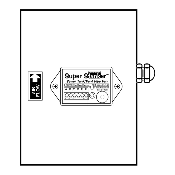
13.5VDC power supply is included). A Fan Monitor constantly measures the fan motor's speed, sounding a warning beeper if the motor stalls. The motor is removable;
replacements are available.
Two 13.5 VDC power supplies can be connected to the same fan. (Power supplies are separately available for this purpose.) In applications with dual sewage lift pumps, this
allows the fan to operate whenever either pump is running, simply by plugging each power supply into separate wall outlets connected to each pump's AC control switch.
STEP-BY-STEP INSTALLATION INSTRUCTIONS
STEP 1: Determine the best mounting location for
the fan (i.e., easy access to the vent pipe and a
nearby 120/240 VAC wall outlet).
Note that the fan must be installed "downwind" of
all feeder pipes, and must be located high enough
to avoid direct exposure to sewage liquids.
Outdoor installation is not recommended, unless
the fan is installed inside a weather-tight
enclosure.
STEP 3: Cut a 6-1/4" inch (160 MM) section out
of the vent pipe at your intended installation point
(use the Vent Pipe Cutting Gauge shown at right
to measure the proper distance). CAUTION:
Make sure the vent pipe is adequately
supported from above before cutting it! Save
this pipe section for temporary use when servicing
the fan.
STEP 4: Trim away any rough edges on both ends
of the open vent pipe, and slip a rubber drain
coupler over each of them. Next, slide the fan in
place over the pipe ends (oriented so that the AIR
FLOW arrow points toward the end of the vent pipe
on the roof), slide the drain couplers into position
(each coupler covering approx 2 inches of the fan
enclosure), and tighten the hose clamps on the
couplers.
Vent Pipe
Fan
Rubber
Drain
Couplers
NOTES:
1. 4" Drain Couplers are shown; installation is
identical for other sizes.
Vent Pipe
2. Installing the fan with PVC pipe cement is not
recommended, since it would hinder any future
attempts to remove the fan for repairs or cleaning.
OPERATION — The LED indicator on the Fan Monitor glows green whenever the fan motor is operating at an adequate speed. If the fan motor stalls, the indicator LED will
flash red instead, and the piezo beeper will sound approx. every 1 second (unless disabled as described in Step 5 above).
WARRANTY— LSL Products warranties this product for a period of ONE YEAR from the date of purchase against defects in materials and workmanship. In the event a
problem, LSL Products will, at its option, repair or replace any defective components, at no charge to the owner. (The owner is responsible for the shipping charges
associated with initial return of the product). IN THE EVENT OF A PROBLEM, PLEASE CONTACT US PRIOR TO RETURNING THE PRODUCT. This warranty does not
cover damage due to unreasonable use of the product. IN NO EVENT SHALL LSL PRODUCTS NOR ANY OF ITS REPRESENTATIVES BE RESPONSIBLE FOR
INCIDENTAL OR CONSEQUENTIAL DAMAGES. This warranty gives you specific legal rights, and you may have other rights which vary from state to state.
REVISION
B
1.
3.
4.
Vent Pipe
13.5VDC Power Supply(s)
Vent Pipe
Sewer Tank / Vent Pipe Fan
STEP 2: If not already present, install a roof-
mounted vent pipe cap, in order to keep debris and
rainwater from falling down into the fan. A simple
vent pipe cap can be made by cementing two 90
degree PVC elbows together, arranged so that the
open end of the 2nd elbow faces downward:
NOTE: A vent pipe cap MUST be
present, or the motor's lifespan will be
drastically reduced.
STEP 5: Strip 1/4" of insulation off the ends of the
13.5VDC Power Supply wires, and connect them
terminals A and B on the Fan Monitor's wire
connection block. (Either wire can go to either
terminal,
because
the
Monitor
provides the fan motor with the correct DC polarity).
Connect the Fan Motor's BLACK (–) wire to
terminal C, the RED (+) wire to terminal D, and the
White or BLUE (Tach) wire to terminal E.
NOTE: If using dual power supplies, connect the STRIPED wire on each
power supply to the same terminal on the Fan Monitor, and the PLAIN
(unstriped) wire on each power supply to the other terminal. This effectively
connects both supplies in parallel, allowing the fan motor to run whenever
either supply is receiving AC power.
Fan Monitor
If operation of the warning beeper is not desired, connect a wire between
terminals F and C. Otherwise, leave terminal F unconnected to anything.
Plug the 13.5VDC Power Supply into a 120/240VAC wall outlet. The Fan
Monitor will briefly beep upon power-up, and the indicator LED will glow
green to confirm that the fan motor is running.
This completes the installation procedure.
2.
5.
automatically
Fan Motor
White or Blue (Tach)
Red (+)
Black (–)
Advertisement
Table of Contents

Summary of Contents for LSL Products Super Stanker
- Page 1 Sewer Tank / Vent Pipe Fan GENERAL INFORMATION — Super Stanker™ is designed to create a slight vacuum inside sewage holding tanks and drain pipes that helps prevent odor infiltration into living areas. The fan's enclosure has the same outside dimensions as 4" Schedule 40 drain pipe, allowing it to be used with a pair of standard 4" rubber drain couplers (Fernco #1056-44 or similar) for easy attachment to 4"...
-
Page 2: Specifications
Nylock Nut, 18-8 SS, #8-32 Fan Motor Assy. w/Grills Enclosure Screw, 18-8 SS, #8-38 x 1" Flush Strain Relief, Airtight Fan Monitor Module DC Power Supply, 13.5 VDC LSL Products • 5804 Babcock Rd. #512 • San Antonio, TX 78240 • www.LSLProducts.net •...
Need help?
Do you have a question about the Super Stanker and is the answer not in the manual?
Questions and answers
How do we order a Super Stanker 4”?